Johni Jonatan Numberi*![]() | Joni
| Joni![]() | Arifia Ekayuliana
| Arifia Ekayuliana![]() | Agri Suwandi
| Agri Suwandi![]() | Pither Palamba
| Pither Palamba![]() | Rombe Allo
| Rombe Allo![]() | Samuel Parlindungan Siregar
| Samuel Parlindungan Siregar![]() | Mickael Ruben Kaiway
| Mickael Ruben Kaiway![]() | Agustinus Giai
| Agustinus Giai![]()
© 2025 The authors. This article is published by IIETA and is licensed under the CC BY 4.0 license (http://creativecommons.org/licenses/by/4.0/).
OPEN ACCESS
This study addressed the urgent need for clean, locally sourced fuels in remote Papuan communities by valorizing sago dregs—an abundant agro‐industrial residue—into bioethanol and assessing its performance in traditional Honai burners. By integrating waste valorization with local cooking practices, this approach aligned with sustainable development goals and supported community resilience. Driven by concerns over indoor air pollution from kerosene and limited electrical grid access, sago dregs underwent acid hydrolysis and yeast fermentation. The distillate was characterized: an 80% v/v ethanol solution exhibited a lower heating value of 16.17 MJ/kg, density of 0.82 g/cm³, viscosity of 1.03 cP, and purity above 61%, while FTIR confirmed minimal impurities. Under optimized conditions, the overall ethanol yield reached 0.42 L/kg of dry sago dregs, demonstrating efficient substrate utilization. Combustion trials in a 14‑jet, 45°‑angled Honai burner at a flow rate of 60 mL/min recorded flame temperatures from 480 to 750℃ after ignition at 90-100℃. Emissions analysis revealed CO at 0.012%, CO₂ at 0.21%, and unburned hydrocarbons at 27 ppm, surpassing kerosene benchmarks and meeting indoor air quality standards. Computational fluid dynamics simulations illustrated symmetrical radial fuel‑air mixing, a concentrated stoichiometric reaction zone, and absence of stagnation, corroborating experimental observations of flame stability and uniform heat distribution. These results demonstrated that bioethanol from sago dregs was technically feasible and culturally appropriate as a renewable household fuel in remote settings, and future work should focus on field‑scale production, burner durability, and life‑cycle analyses to confirm economic viability and environmental benefits.
sago dregs, bioethanol properties, combustion performance, Honai burner, energy solution, heat release
Indonesia’s bioethanol demand is projected to increase 10-15% by 2025, reaching a total requirement of 30,833,000 L/month [1]. By 2025, biofuels, including bioethanol, are projected to replace 1.48 billion liters of gasoline, accounting for 5% of hydrocarbon consumption in the country [2]. This transition is in line with the objective of the government to gradually adopt renewable energy system by 2050 [3]. Meanwhile, bioethanol is manufactured from local plants, such as cassava [4-6], avocado [7, 8], corncobs [9], Napier grass [10], and sago [11-14]. Sago is highly valuable for carbohydrates, and cellulose production is essential for manufacturing bioethanol [15]. Each stem produces 200 to 500 kg of moist starch annually, equivalent to 25 to 30 tons per hectare, which is a significant energy source [16]. An estimated 51.3% of sago fields globally, with the potential for bioethanol fuel production, are located in Indonesia [17].
Based on available statistics, there are approximately 2,460,000 hectares of sago fields globally. This area is divided into 225,000 hectares and 210,000 hectares of natural and plantation lands, respectively, with 56% of the total land in Indonesia. However, Indonesia and Papua New Guinea possess natural sago fields found exclusively in Papua and Maluku regions. Papua has 1,200,000 hectares and 14,000 hectares of natural and plantation lands, respectively, meaning that 88% of sago fields are in the region. This highlights Papua's significant potential for developing new energy sources [11].
Bioethanol (C2H5OH), an alternative fuel, is more environmentally friendly compared to kerosene, produces fewer carbon emissions, and is derived from renewable resources [11]. However, extensive research and awareness campaigns are needed, specifically concerning the utilization of sago dregs waste for bioethanol production. The analysis conducted using photo-scanning electron microscopic EDX testing showed the structure of the hydrocarbon components in Papuan sago dregs comprised significant carbon content of 70.91% and 76.49% by dry and wet weights, respectively. Dregs also contained oxygen, constituting approximately 28.95% and 23.45% by dry and wet weights, including 0.14% and 0.06% silicone by dry and wet weights, respectively. In addition, it comprised 82.4%, 10.4%, 3.64%, 1.85%, 1.70%, and 0.01% of carbohydrates, water, ash, proteins, coarse fiber, and fat [15].
While the potential of sago dregs bioethanol is evident, there is a critical research gap concerning its practical application as a household fuel, specifically within traditional cooking devices like the Honai Burner, which are integral to Papuan households in isolated areas. Despite bioethanol's environmental advantages over kerosene, including fewer carbon emissions, comprehensive studies on the performance characteristics, flame behavior, and exhaust gas emissions of sago dregs bioethanol when utilized in Honai Burners are notably absent in existing literature. Addressing this specific gap is crucial for developing tailored, efficient, and environmentally sound energy solutions that are culturally appropriate and contribute directly to regional energy independence for these communities.
The fundamental combustion characteristics of bioethanol is paramount for optimizing burner performance and ensuring safe, efficient domestic energy solutions [18]. Key parameters include the air-fuel ratio (AFR), which defines the proportion of air to fuel necessary for complete combustion, and the stoichiometry of hydrocarbon fuels [19]. Flame characteristics, such as the behavior of diffusion and laminar flames, are also critical, as their energy content influences reactant diffusion and overall stability [20]. Furthermore, burner geometry, including the size of jet holes and nozzle design, significantly impacts flame stability and overall burner performance [21], making its precise consideration vital for the Honai Burner application.
To date, no studies have evaluated sago‐dregs bioethanol in the context of Honai burner stoves, a key domestic energy technology for isolated Papuan communities. Despite sago’s established potential, no studies have evaluated its bioethanol in Honai burners. This work thus aims to: (1) identify optimal sago-dregs bioethanol concentrations through physicochemical analysis; and (2) assess combustion performance in a 45°-angled, 14-hole Honai burner. By linking fuel chemistry to burner performance, this study provides actionable insights for sustainable household energy solutions in Papua.
The method comprised two phases, namely pre-experimental and experimental. The characteristics of bioethanol fuel derived from sago dregs were determined in the pre-experimental phase. The experimental phase includes setting up combustion equipment to collect data on flame temperature distribution, hot gas, and smoke behavior, pressure distribution in the tube and burner, exhaust gas production during the combustion, flame phenomena, and height.
2.1 Pre-experimental characterization
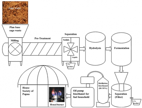
Figure 1 shows the method of producing fuel from sago dregs, namely milling, hydrolysis, fermentation, and distillation. The distillation method produces the fuel, which is subsequently pumped into Honai Burner for usage.
Figure 1. Production method of sago dregs bioethanol
The pre-experimental method yielded 80% v/v bioethanol. These concentrations produced sufficient flame output than values above 60%. Bioethanol is transferred into the conduit, connected to a flowmeter-controlled hose, for further experimentation. The pre-experiment aims to determine the optimal bioethanol concentration with sufficient flame performance when used in Honai Burner. Based on the measurement result, the most optimal concentration for fueling Honai Burner was determined.
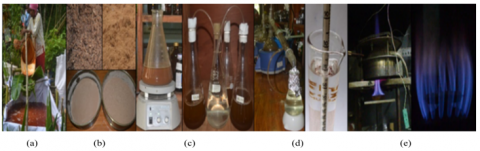
Figure 2. Pre-experimental set-up for the production of bioethanol from sago dregs (a) Sago collection process, (b) Sago dregs, (c) Fermentation process, (d) Distillation process, (e) Honai burner
Figure 2 illustrated the sequential experimental procedures undertaken in the production of bioethanol from sago dregs. In subfigure (a), the process began with the collection and preparation of sago dregs, which were obtained as a fibrous by-product of starch extraction. The dregs were first sun-dried to reduce moisture content, then milled and sieved to obtain a uniform particle size. This step was essential to increase the surface area for subsequent chemical reactions and improve the efficiency of hydrolysis.
Subfigure (b) showed the acid hydrolysis stage, where the prepared dregs were treated with a dilute sulfuric acid solution. This pretreatment served to break down complex carbohydrates—primarily cellulose and hemicellulose—into fermentable monosaccharides such as glucose and xylose. The hydrolysis was conducted under controlled temperature and duration to optimize sugar yield while minimizing the formation of inhibitory compounds such as furfural.
In subfigure (c), the hydrolysate was transferred to fermentation vessels and inoculated with Saccharomyces cerevisiae. The fermentation process was carried out anaerobically for 72 hours at an optimal temperature of approximately 30℃. During this period, the yeast metabolized the simple sugars into ethanol and carbon dioxide. Regular monitoring of parameters such as pH, temperature, and sugar concentration ensured optimal conditions for yeast activity and ethanol production.
Subfigure (d) depicted the post-fermentation phase, where the broth was filtered to separate the ethanol-containing liquid from residual solid biomass. The filtration process improved the clarity of the ethanol solution and minimized the risk of clogging in the distillation apparatus. This step was crucial for enhancing the purity and yield of the final product.
Finally, subfigure (e) presented the distillation phase, in which the ethanol-water mixture was subjected to fractional distillation. By leveraging the difference in boiling points between ethanol and water, ethanol was separated and collected at a concentration of over 80%. The distillate was then characterized based on parameters such as specific gravity, viscosity, and low heating value to confirm its suitability as a renewable fuel.
The output of the entire pre-experimental method was bioethanol, which was used as fuel in the burner. In addition, five tests were conducted to ascertain the quality of bioethanol, such as low heating value (LHV), specific gravity, viscosity, gas chromatography, and Fourier transform infrared (FITR).
The first quality assessment included determining LHV according to the ASTM D4809-09, a standard method for precisely measuring the heat of liquid hydrocarbons using a bomb calorimeter [22]. Four specific apparatuses were used in the test, namely a bomb, calorimeter, jacket, and thermometer. The method was applied to calculate temperature changes before, during, and after combustion, and in the pre-experimental method, bioethanol samples with varied concentrations were used. Each sample, weighing 1.0 g, is placed in the bomb and ignited while measuring temperature of the surroundings. In addition, the varying temperature was further used to calculate LVH of the sample.
In the second stage, the specific gravity of bioethanol was measured using a pycnometer, adhering to the ASTM D1298 method. This method entailed filling a pycnometer of known weight with bioethanol sample. Subsequently, the pycnometer was immersed in a water bath at 15℃ to stabilize temperature. The weight comparison of the pycnometer before and after the pycnometer was filled with the sample at 15℃ was used to calculate the specific gravity.
Viscosity was measured in the third stage based on the ASTM D445-23 standard. This test included the use of a calibrated glass capillary as a viscometer. Viscosity value was determined by measuring the time it takes for a volume of bioethanol sample to flow under gravity through the glass [23].
In the fourth stage, the gas chromatography was measured using Shimadzu GC-2010 [24]. The steps included injecting bioethanol sample into the GC-2010 instrument, which then analyzed and generated the measurement results.
FTIR test was conducted using the SupelCowax-10 at temperature of 50℃ in the fifth stage. A 50 µL sample of bioethanol was put on the plate in the SupelCowax-10 equipment. The test output showed bioethanol content based on the response to the infrared spectrum.
2.2 Combustion experiments
In the second phase, experiments were conducted to measure the performance of flame produced by the burner. This included measuring the laminar jet flame diffusion of bioethanol through direct visualization and determining flame temperature using a thermocouple [25]. Combustion byproduct gases were measured using a flue gas analyzer, while burner pressure and fuel flow rate were determined using pressure and flow meters, respectively [26]. Another experiment was conducted in a combustion chamber equipped with 14 holes and varying concentrations of bioethanol fuel.
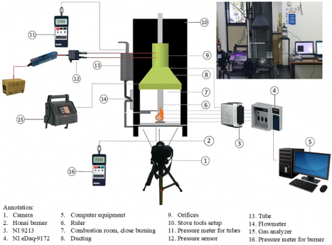
The experimental setup, shown in Figure 3, mainly used National Instrument equipment such as the NI 9213 and NI cDaq-9172 to measure temperature of flame. These instruments are connected to the computer, facilitating the measurement data recording using LabView software. Furthermore, a DSLR Camera was positioned in front of the burner to capture the entire combustion. The data from the experiment were recorded using LabView software, with Table 1 showing the eleven steps.
Figure 3. Experimental set-up
Table 1. Steps of the experiment
|
No. |
Steps of the Experiment |
Equipment Used at the Experiment |
|
1 |
Prepare the apparatus required to conduct the test |
Stove, burner, bioethanol tube, flow meter, thermocouple, flue gas analyzer, pressure meter, pressure transducer, pressure drop sensor, camera, tripod, and AC-DC inverter |
|
2 |
Setup a computer with the software LabView and Lutron Pressure Transducer |
Lutron Pressure Transducer |
|
3 |
Ensure bioethanol concentration is appropriate |
Alcohol meter |
|
4 |
Prepare 500 ml bioethanol fuel with the selected concentration |
Measuring cup |
|
5 |
Fill bioethanol containers |
|
|
6 |
Adjust the fuel consumption rate |
Flow meter |
|
7 |
Combustion occurred for ten minutes without waiting for the fuel to run out |
|
|
8 |
Flame temperature and several other temperatures at other sites were recorded |
LabView software |
|
9 |
The pressure in the conduit and burner was recorded |
LabView software |
|
10 |
Record the exhaust gas output and pressure decrease |
Flue gas analyzer and transducer |
|
11 |
The fuel rate closed after 10 minutes |
Flowrate |
|
12 |
Observe the residual burning fuel until the fire is extinguished and the recording stopped |
|
3.1 Physicochemical characterization of bioethanol
The physicochemical analysis of bioethanol from sago dregs assessed its potential as a fuel for traditional burners, revealing a Lower Heating Value (LHV) of 16.166 MJ/kg per ASTM D4809-09 standards, indicative of its adequate energy content for efficient combustion in domestic burner applications.
The bioethanol's specific gravity was ascertained via a pycnometer at regulated temperature, yielding a measurement of 0.82 g/cm³. This relatively low density suggests that the fuel can flow easily through the burner’s distribution system without the need for high pressure, which is advantageous for gravity-fed or low-pressure combustion setups.
Furthermore, the kinematic capillary viscometer was utilized to ascertain the viscosity of bioethanol, thus measuring its internal flow resistance. The measured viscosity was 1.03 cP, a value characteristic of light liquid fuels. Such low viscosity is crucial for ensuring fine atomization and homogeneous mixing with ambient air, thereby facilitating clean and stable flame formation. These physicochemical properties collectively demonstrate that sago-dregs bioethanol possesses the necessary attributes for efficient and reliable performance in traditional biomass burner configurations. This phenomenon is ascribed to the lower viscosity of ethanol solutions compared to water, whereby an increase in bioethanol concentration correlates with elevated content [17].
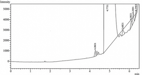
Figure 4. Gas chromatography results of 80% concentration bioethanol
The GC-2010 gas chromatography apparatus was employed to assess bioethanol concentration, with Figure 4 illustrating the resultant data; the analysis verified ethanol's presence in bioethanol utilized as fuel, founded on graphical and tabular evaluations indicating an 80% concentration level.
The chromatographic examination of the bioethanol specimen obtained from the fermentation and distillation of sago dregs hydrolysate was conducted utilizing gas chromatography, employing a standard ethanol reference for the calibration of retention time, where the x-axis denotes retention time (minutes) and the y-axis signifies detector response (arbitrary units), thereby depicting the concentration of volatile components eluted from the column.
The major peak appeared at a retention time of approximately 2.2 minutes, corresponding to pure ethanol as confirmed by comparison with the standard reference. The sharpness and dominance of this peak indicate that ethanol was the principal component in the distillate, suggesting a successful fermentation and separation process.
Minor peaks detected at extended retention times (generally between 3-5 minutes) likely indicate the presence of trace volatile compounds, including methanol, acetaldehyde, or higher alcohols (e.g., propanol, butanol), which are typically generated in minimal amounts during fermentation. The presence of secondary peaks at markedly reduced intensity indicates minimal impurities and an efficient distillation process for ethanol concentration.
The clean profile of the chromatogram—with a high ethanol peak and negligible contaminants—validates the efficiency of both the fermentation process using Saccharomyces cerevisiae and the fractional distillation setup. The result confirms that the sago dregs-derived ethanol meets basic purity standards suitable for combustion testing in the Honai Burner.
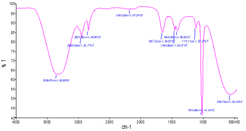
FTIR data collection served as a valuable tool for discerning organic and inorganic substances [27]. The collection was used to make educated guesses about the proportions of mixtures containing sago dregs and bioethanol. Figure 5 shows the data obtained from the measurements, focusing on bioethanol with an 80% concentration. Significant infrared absorption was observed in bioethanol spectrum due to O-H or alcohol stretching at 3339.07 cm-1, designated as the absorption area. Meanwhile, the absorption waves at 2949.08 cm-1 signified C-H stretching groups or alkanes. Absorption at 1647.33 cm-1 and 1015.06 cm-1 showed the presence of a C=C or alkene and C=C+OH or ether bending groups, respectively. These two types of absorption showed the presence of a carbon-carbon double bond.
Figure 5. FTIR results of 80% concentration bioethanol test
3.2 Flame temperature profile
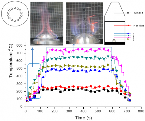
The performance evaluation of Honai burner, fueled by 80% bioethanol, included analyzing the jet flame temperature at a 45-degree angle. The investigation utilized six methodically arranged thermocouples within the combustion chamber to evaluate flame temperatures at specified points 1, 2, 3, and 4, in addition to the resulting heated gases and emissions. The aim was to measure the performance of the burner with the 80% bioethanol fuel. The experiment was conducted on a burner with 14 holes positioned at a 45-degree angle, maintaining a consistent air-to-fuel mass ratio of 60 mL/min. It started with a preheating zone, which lasted approximately two minutes, with an ignition temperature of 90 to 100℃. Moreover, the combustion phase persisted for approximately 8 minutes, during which the flame exhibited stability, maintaining temperatures between 480 and 750℃, while the fuel mass flow rate was consistently held at 60 mL/min. This phase demonstrated flame stability, exemplified by the jet flame phenomenon illustrated in Figure 6.
Figure 6. Temperature distribution on Honai Burner for 14-hole degrees 45
The performance evaluation of Honai burner, fueled by 80% bioethanol, included analyzing the jet flame temperature at a 45-degree angle. Six strategically placed thermocouples within the combustion chamber assessed flame temperatures at designated positions 1 through 4, along with the temperatures of the resultant hot gases and smoke. The objective was to evaluate the burner’s efficacy utilizing an 80% bioethanol fuel mix. The experimental setup involved a burner with 14 apertures angled at 45 degrees, sustaining a fixed air-to-fuel ratio of 60 mL/minute, commencing with a preheating phase of approximately two minutes to reach an ignition temperature of 90 to 100℃, followed by an eight-minute combustion phase demonstrating stable flame characteristics with temperatures between 480 to 750℃, as depicted in Figure 7.
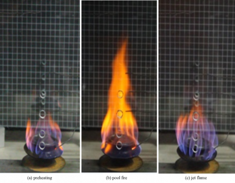
Figure 7. Flame stability
Visually captures the flame formed by the 80% bioethanol during operation. A distinct three-zone flame was observed: a blue core reaction zone (≈10 mm), a luminous yellow plume (≈90 mm), and a yellow product zone (≈40 mm). The blue flame near the burner orifices is characteristic of clean ethanol combustion, while the elongated yellow tip represents complete oxidation of unburned hydrocarbons. This jet-flame morphology is consistent with the laminar diffusion flame structures described in ethanol burner studies by Chen et al. [18] and Boulanger [28]. The absence of flickering or irregular flame shapes further confirmed flame stability, which is essential for safe household cooking environments.
3.3 Emission performance
The Honai burner operated at a constant fuel flow rate of 60 mL/min, supported by a stable pressure reading of approximately 0.85 psi. Maintaining this flow regime was critical to prevent flame blow-off or backfire. This aligns with Awg-Adeni et al. [11], who demonstrated that the stability of nozzle pressure markedly affects both flame stability and heat distribution in residential ethanol burners. The use of 14 uniformly spaced jet holes ensured symmetrical distribution of flame and heat, minimizing localized hotspots and enhancing energy efficiency.
Emission analysis demonstrated superior results: CO at 0.012%, CO₂ at 0.21%, and HC at 26 ppm, significantly lower than kerosene stoves, which generally show CO levels > 0.08% and HC > 100 ppm under similar thermal conditions; these low values indicate complete combustion due to the high oxygen content (35%) in bioethanol, facilitating full oxidation, and comply with or surpass WHO indoor air quality standards, thereby making sago-dregs ethanol viable for indoor cooking in rural settings.
3.4 CFD simulation as a validation
The velocity contour plots from the CFD analysis in Figure 8 further validated the experimental findings. Bioethanol jets diffused radially outward while the oxidizing air entered from the upper zone, forming a converging counterflow pattern. The region of peak velocity aligned with the stoichiometric reaction zone, where the mixture of ethanol vapor and air combusted most efficiently. The simulation also confirmed that the burner design avoided flow stagnation zones or vortices that could reduce combustion efficiency or cause instability. Similar fluid-dynamic behavior was described in numerical studies by Zhen et al. [29], where optimal burner performance was linked to symmetrical jet–air interaction patterns.
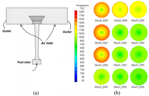
We undertook a related experimental approach to analyze the thermal dynamics of a specifically engineered burner, as represented in Figure 8. The study encompassed two variable parameters—the aperture diameter and the spatial separation between the burner head and the cooker’s base—and the modifications were aimed at delineating the precise configurations essential for attaining optimal flame temperatures.
Figure 8. Şener burner [30] (a) 3D model of the burner (b) Temperature of the burner with variated distance from bottom to head burner (5 cm, 10 cm, 30 cm), and cocker diameter (25 cm, 30 cm, 35 cm)
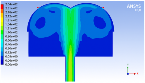
Figure 9. The contour of fuel fusion speed in Honai Burner
The findings from Şener et al. [30], illustrated in Figure 8, suggest that proximity to the hole did not correspond with the recorded peak temperature. The highest temperature of Seners Burner was recorded at a distance of 10 cm, reaching 1008 K or 734℃ [26]. Similarly, in Honai Burner experiment, the highest temperature was recorded at thermocouple number 3, located second to the burner, with temperature of 750℃, as shown in Figure 7. A numerical simulation using CFD (computational fluid dynamics) was carried out on Honai Burner to identify the fluid flow patterns and the mixing of fuel and air. This simulation aimed to analyze experimental outcomes, emphasizing variables including velocity, pressure, and thermal conditions. Combustion chamber walls were modeled as glass-like solid boundaries, separating the chamber from the surrounding air. The aim was to ensure that the conditions in the combustion chamber were similar to the ones outside.
Figure 9 presents a contour map illustrating the spatial distribution of fuel fusion speed, defined here as the rate at which liquid bioethanol transitions into vapor within the Honai Burner during combustion. This process—fuel vaporization or phase change—is a key determinant of combustion efficiency, as it influences how evenly and rapidly the fuel mixes with air and ignites.
The diagram employs a color gradient to illustrate varying fusion velocities within the burner’s cross-section, with red and orange regions denoting areas of elevated fusion rates indicative of intense ethanol fuel heating, rapid vaporization, and probable combustion activity, predominantly situated near the burner nozzle or central flame core where temperatures and convective heat transfer are maximal.
Conversely, zones displayed in blue or green reflect lower fusion speeds, suggesting incomplete vaporization or reduced thermal energy input. These cooler regions are commonly observed near the burner walls or toward the exhaust path, where heat dissipation and thermal losses reduce the rate of phase transition. Such areas may indicate suboptimal burner geometry or insufficient turbulence, which can lead to delayed combustion or unburnt fuel residues.
A replica with dimensions of 110 mm by 45 mm was fabricated to represent the size of the combustion chamber in Honai Burner. In the computational analysis, the term remaining bioethanol exhaust gas refers to the pressure-outlet condition necessary to release the exhaust gas flow rate. To simulate direct contact with the surrounding air, the bottom wall of the chamber is designated as velocity inlet with zero airflow. Velocity distribution vector of the enclosed bioethanol fluid is ignored, while the fuel flow rate is set at 60 mL/minute. This method ensures consistency in fuel speed exiting the burner mouth, allowing the jets to expand to the burst limit in the combustion chamber system. However, the word area signifies the region where the fuel reaction rate and mass fraction remained unchanged due to minimal impact from viscous shear forces and potential-core diffusion. There is no change in the molecular weight of bioethanol gas spray, maintaining consistent density. Figure 9 shows the results of CFD simulation performed on Honai Burner. It shows velocity contours of the fuel wick in Honai Burner, with bioethanol fuel diffusing radially outward while the air, acting as the oxidizer, diffuses inward. The reaction zone near flame surface represents the region where bioethanol-oxygen mixture achieves stoichiometric conditions, producing laminar combustion.
This study demonstrated the feasibility of producing second-generation bioethanol from sago dregs and its application as a renewable fuel in the Honai Burner—an energy device tailored to the cultural and spatial context of rural Papua. The physicochemical characterization confirmed that the ethanol produced met acceptable parameters for combustion, with a specific gravity of 0.827 g/cm³, a viscosity of 1.72 cP, and a lower heating value of 16.166 MJ/kg. Combustion tests showed a stable flame and a peak temperature of 943℃, confirming the burner’s operational effectiveness. Gas chromatography analysis validated the ethanol's purity, with only minor by-products detected.
Nevertheless, it is important to acknowledge several limitations; the experimental study was performed in a controlled laboratory environment with a restricted sample size and a singular burner configuration, failing to consider real-world factors such as variations in sago dregs composition, climate-dependent drying conditions, and diverse user operations, while also neglecting to measure emissions from bioethanol combustion, including possible aldehyde emissions in inadequately ventilated areas, which constitutes a significant gap in evaluating health repercussions.
Future research should focus on optimizing the Honai Burner design for improved thermal efficiency, possibly through better air-fuel mixing or preheated combustion air. Scaling up ethanol production at the village level requires further investigation into modular distillation systems, decentralized logistics, and cost-benefit modeling. Moreover, long-term field testing under actual household conditions is necessary to validate durability, user acceptance, and safety. A full life-cycle analysis (LCA) could further inform the environmental and economic implications of adopting sago-based bioethanol as a sustainable energy solution in remote regions.
The authors acknowledge the support of Cenderawasih University, LPPM of Cenderawasih University, and Engineering Faculty of Cenderawasih University.
[1] Mujiyanto, S., Tiess, G. (2013). Secure energy supply in 2025: Indonesia’s need for an energy policy strategy. Energy Policy, 61: 31-41. https://doi.org/10.1016/j.enpol.2013.05.119
[2] Suntana, A.S., Vogt, K.A., Turnblom, E.C., Upadhye, R. (2009). Bio-methanol potential in Indonesia: Forest biomass as a source of bio-energy that reduces carbon emissions. Applied Energy, 86: S215-S221. https://doi.org/10.1016/j.apenergy.2009.05.028
[3] Yudiartono, Y., Windarta, J., Adiarso, A. (2023). Sustainable long-term energy supply and demand: The gradual transition to a new and renewable energy system in Indonesia by 2050. International Journal of Renewable Energy Development, 12(2): 419-429. https://doi.org/10.14710/ijred.2023.50361
[4] Numjuncharoen, T., Papong, S., Malakul, P., Mungcharoen, T. (2015). Life-cycle GHG emissions of cassava-based bioethanol production. Energy Procedia, 79: 265-271. https://doi.org/10.1016/j.egypro.2015.11.477
[5] Papong, S., Malakul, P. (2010). Life-cycle energy and environmental analysis of bioethanol production from cassava in Thailand. Bioresource Technology, 101(1): S112-S118. https://doi.org/10.1016/j.biortech.2009.09.006
[6] Soeprijanto, S., Qomariyah, L., Hamzah, A., Altway, S. (2022). Bioconversion of industrial cassava solid waste (Onggok) to bioethanol using a saccharification and fermentation process. International Journal of Renewable Energy Development, 11(2): 357-363. https://doi.org/10.14710/ijred.2022.41332
[7] Ginting, M.H.S., Irvan, Misran, E., Maulina, S. (2020). Potential of durian, avocado and jackfruit seed as raw material of bioethanol: A review. IOP Conference Series: Materials Science and Engineering, 801(1): 012045. https://doi.org/10.1088/1757-899X/801/1/012045
[8] Rahman, H., Nehemia, A., Astuti, H.P. (2023). Investigating the potential of avocado seeds for bioethanol production: A study on boiled water delignification pretreatment. International Journal of Renewable Energy Development, 12(4): 648-654. https://doi.org/10.14710/ijred.2023.52532
[9] Chandrasiri, Y.S., Weerasinghe, W.M.L.I., Madusanka, D.A.T., Manage, P.M. (2022). Waste-based second-generation bioethanol: A solution for future energy crisis. International Journal of Renewable Energy Development, 11(1): 275-285. https://doi.org/10.14710/ijred.2022.41774
[10] Yasuda, M., Ishii, Y., Ohta, K. (2014). Napier grass (Pennisetum purpureum Schumach) as raw material for bioethanol production: Pretreatment, saccharification, and fermentation. Biotechnology and Bioprocess Engineering, 19(6): 943-950. https://doi.org/10.1007/s12257-014-0465-y
[11] Awg-Adeni, D.S., Bujang, K.B., Hassan, M.A., Abd-Aziz, S. (2013). Recovery of glucose from residual starch of sago hampas for bioethanol production. BioMed Research International, 2013(1): 1-8. https://doi.org/10.1155/2013/935852
[12] Bukhari, N.A., Loh, S.K., Abu Bakar, N., Ismail, M. (2017). Hydrolysis of residual starch from sago pith residue and its fermentation to bioethanol. Sains Malaysiana, 46(8): 1269-1278. https://doi.org/10.17576/jsm-2017-4608-12
[13] Vincent, M., Anak Senawi, B.R., Esut, E., Muhammad Nor, N., Awang Adeni, D.S. (2015). Sequential saccharification and simultaneous fermentation (SSSF) of sago hampas for the production of bioethanol. Sains Malaysiana, 44(6): 899-904. https://doi.org/10.17576/jsm-2015-4406-17
[14] Rijal, M. (2020). Bioethanol from sago waste fermented by baker’s and Tapai yeast as a renewable energy source. Developmental Biology. https://doi.org/10.1101/2020.01.03.894691
[15] Dhiputra, I.M.K., Jonatan, N.J. (2015). The utilization of metroxylon sago dregs for eco-friendly bioethanol stove in Papua, Indonesia. KnE Energy, 2(2): 119-125. https://doi.org/10.18502/ken.v2i2.366
[16] Susanto, B., Tosuli, Y.T., Adnan, Cahyadi, Nami, H., Surjosatyo, A., Alandroe, D., Nugrohoe, A.D., Rashyid, M.I., Muflikhun, M.A. (2024). Characterization of sago tree parts from Sentani, Papua, Indonesia for biomass energy utilization. Heliyon, 10(1): e23993. https://doi.org/10.1016/j.heliyon.2024.e23993
[17] Jonatan, N.J., Ekayuliana, A., Diputra, I.M.K., Nugroho, Y.S. (2017). Analysis of the heat release rate of low-concentration bioethanol from sago waste. International Journal of Technology, 8(3): 428. https://doi.org/10.14716/ijtech.v8i3.6423
[18] Chen, J., Peng, X., Yang, Z., Cheng, J. (2009). Characteristics of liquid ethanol diffusion flames from mini tube nozzles. Combustion and Flame, 156(2): 460-466. https://doi.org/10.1016/j.combustflame.2008.08.007
[19] Oliverio, N., Stefanopoulou, A., Jiang, L., Yilmaz, H. (2009). Ethanol detection in flex-fuel direct injection engines using in-cylinder pressure measurements. SAE International Journal of Fuels and Lubricants, 2(1): 229-241. https://doi.org/10.4271/2009-01-0657
[20] Yousufuddin, S. (2018). Combustion duration influence on hydrogen-ethanol dual fueled engine emissions: An experimental analysis. Journal of Mechatronics, Electrical Power, and Vehicular Technology, 9(2): 41-48. https://doi.org/10.14203/j.mev.2018.v9.41-48
[21] Widiyanti, W., Mizar, M.A., Wicaksana, C.A., Nurhadi, D., Moses, K.M. (2019). Exhaust emissions analysis of gasoline motor fueled with corncob-based bioethanol and RON 90 fuel mixture. Journal of Mechatronics, Electrical Power, and Vehicular Technology, 10(1): 24-28. https://doi.org/10.14203/j.mev.2019.v10.24-28
[22] Sugiarto, B., Kurniawan, A., Perdana, A. (2020). Plastic waste conversion into fuel by utilizing biomass waste as heating system on pyrolysis process. Journal of Physics: Conference Series, 1517(1): 012010. https://doi.org/10.1088/1742-6596/1517/1/012010
[23] Muhaji, Sutjahjo, D.H. (2018). The characteristics of bioethanol fuel made of vegetable raw materials. IOP Conference Series: Materials Science and Engineering, 296: 012019. https://doi.org/10.1088/1757-899X/296/1/012019
[24] Joni, Numberi, J.J., Tambing, E., Siregar, S.P., Setiawan, R.P.A., Tambunan, A.H., Siregar, K. (2023). Evaluating the application of bubble wet scrubber systems for gas cleaning in gasification. Instrumentation Mesure Métrologie, 22(1): 21-27. https://doi.org/10.18280/i2m.220103
[25] Elias, J., Faccinetto, A., Batut, S., Carrivain, O., Sirignano, M., D’Anna, A., Mercier, X. (2023). Thermocouple-based thermometry for laminar sooting flames: Implementation of a fast and simple methodology. International Journal of Thermal Sciences, 184: 107973. https://doi.org/10.1016/j.ijthermalsci.2022.107973
[26] Shi, B., Hu, J., Peng, H., Ishizuka, S. (2018). Effects of internal flue gas recirculation rate on the NO emission in a methane/air premixed flame. Combustion and Flame, 188: 199-211. https://doi.org/10.1016/j.combustflame.2017.09.043
[27] Joni, Setiawan, R.P.A., Siregar, K. (2023). Analysis of characteristics empty palm bunches using the FT-IR and pyrolysis-GCMS methods. G-Tech: Jurnal Teknologi Terapan, 7(2): 377-385. https://doi.org/10.33379/gtech.v7i2.2251
[28] Boulanger, J. (2010). Laminar round jet diffusion flame buoyant instabilities: Study on the disappearance of varicose structures at ultra-low Froude number. Combustion and Flame, 157(4): 757-768. https://doi.org/10.1016/j.combustflame.2009.12.005
[29] Zhen, H.S., Choy, Y.S., Leung, C.W., Cheung, C.S. (2011). Effects of nozzle length on flame and emission behaviors of multi-fuel-jet inverse diffusion flame burner. Applied Energy, 88(9): 2917-2924. https://doi.org/10.1016/j.apenergy.2011.02.040
[30] Şener, R., Özdemi̇R, M., Yangaz, M. (2019). Effect of the geometrical parameters in a domestic burner with crescent flame channels for an optimal temperature distribution and thermal efficiency. Journal of Thermal Engineering, 5(6): 171-183. https://doi.org/10.18186/thermal.654303