Md. Moniruzzaman Bhuyan*![]() | Mashky Chowdhury Surja
| Mashky Chowdhury Surja![]() | Ujjwal Kumar Deb
| Ujjwal Kumar Deb![]()
© 2025 The authors. This article is published by IIETA and is licensed under the CC BY 4.0 license (http://creativecommons.org/licenses/by/4.0/).
OPEN ACCESS
This study investigates the heat transfer enhancement in a tubular pipe using various rectangular-cut twisted tape inserts with a twist ratio of 5.25. Numerical simulations are carried out for twisted-tape inserts of different configurations, containing three types of rectangular-cuts (cut-1: 8×6×14 mm3, cut-2: 8×10×18 mm3, cut-3: 8×12×26 mm3) and compared with B. Salam cut (8×8×14 mm3) and plane twist configuration. The simulations are conducted over a Reynolds number range of 9471-42623 under uniform temperature conditions. The tubular pipe length is set at 1000 mm, with a twisted tape length of 960 mm. Water is used as the working fluid. The study examines the impact of these inserts on the temperature distribution, vorticity, Nusselt number (Nu), friction factor (f), effectiveness (ε) and thermal performance efficiency (η). The simulation results reveal that the presence of rectangular-cuts in twisted tape inserts leads to significant enhancement in heat transfer compared to plane inserts. At the Reynolds number of 14207, the Nusselt number is observed to be 188.67 for plane twist configuration, which improves by 17.66%, 12.88% and 13.69% for cuts 1, 2 & 3 respectively while for B. Salam cut and without insert, it is found to improve by 15.64% and 7.94% respectively. When it comes to effectiveness, B. Salam cut results in an improvement by 20.70% while cuts 1, 2 and 3 yield an improvement of 10.08%, 19.88% and 19.60% compared to the plane tube for the Reynold’s number of 18,943. The friction factor shows decreasing pattern for all cases with the best results obtained for cuts 2, 3 and B. Salam cut. In presence of cuts, the thermal performance efficiency shows an upward trend from 1.97-3.17 over the studied Reynolds number range. The results obtained from the numerical simulations show good qualitative agreement with results obtained from experimental studies by B. Salam, indicating that the enhancement in heat transfer not only depends on the type of inserts but also on the specific twist and cut configurations.
rectangular-cut twisted tape inserts, Reynolds number, thermal performance, friction factor, numerical simulations
Twisted tapes and tubes have been used for a long time as a passive technique to enhance the transfer of heat in fluid transfer pipes and heat exchangers. Out of the many thermal applications, chemical processing facilities, solar heaters and power plants systems are just a few of them. The ongoing demand for improved thermal management in various industrial applications has encouraged extensive research into innovative methods for enhancing heat transfer in tubular systems. Among these methods, the use of twisted tape inserts has emerged as a highly effective technique for augmenting heat transfer by inducing swirl flow and disrupting the thermal boundary layer. However, traditional twisted tape designs, while effective, often come with limitations, such as increased pressure drops and friction factors that can offset the benefits of enhanced heat transfer. To address these challenges, researchers have explored various modifications to twisted tape designs, including the incorporation of cuts and variations in twist ratios [1-5].
The enhancement of heat exchanger performance can be attained by various active and passive techniques of heat transfer enhancement like using corrugated tubes [6] and conical tubes [7]. Inserts of different geometries are used to enhance the performance of heat exchangers [8-13]. These inserts and geometries are of different shapes, such as three different obstacle shapes [14], wire springs [15], twisted tapes with rectangular cuts [16], circular cuts [17], V-cuts [18], single & double cuts [19], twist ratio [20], perforated inserts [21], square cut insert [22], short [23] & full length inserts [24] and fins [25, 26]. A study was carried out to learn the effect of multi-tube helical heat exchangers for turbulent flow [27]. These inserts can be easily produced, replaced and removed for maintenance. Therefore, numerous possible changes can be made, which include changes in their geometrical shape.
In 2016, an experimental study was conducted on the turbulent flow inside the helically corrugated heat exchanger fitted with two U-cut and a V-cut twisted-tape inserts by Hasanpour et al. [28]. With the hole diameter ratios 0.11 and 0.33 along with the width and depth ratios of the cuts from 0.3-0.6, the experiment was conducted for the twist ratio of the inserts 3, 5 and 7 for Reynold’s number from 5000-15000. The Nusselt number is increases a maximum of about 40% in presence of V-cut and U-cut in twisted tape inserts for width ratio of 0.3 and depth ratio of 0.45 at the twist ratio of 3 [28].
The results obtained by Acharjee et al. [29] in 2019 show that the angle of perforated inserts impacted the Nusselt number and thermal performance evaluation criterion. Among the angles taken into consideration, the perforation angle of 65º resulted in the Nusselt number increasing by 1.11-1.13 times and the thermal performance criterion improving by 1.10-1.13 times compared to the 0º angle. The Nusselt number consistently remained higher for the angle of perforation of 65º compared to other angles studied across all Reynold’s numbers.
Numerical and experimental investigations were conducted by Marzouk et al. [30] on the heat transfer enhancement in double tube heat exchanger using nail-rod inserts. The results indicate an increase in the Nusselt (Nu) number by 1.81-1.90 times upon the introduction of nail rods compared to the plane tube. The maximum increase in energy efficiency is found to be 1.28 times more compared to the plane tube.
Sharaf et al. [31] studied the heat transfer enhancement in a double pipe helical heat exchanger using spring wire inserts and nanofluid. For the Reynolds number 4500-7000, the Nusselt number is enhanced by 34% when 0.1% volume concentration of nanofluid is used and by 43.5% while the maximum pressure drop ratio of 1.57 is obtained when spring wire is only used compared to base water with nanofluid employment and spring wire inserts.
According to Poblador-Ibanez et al. [32], vorticity modifies the fluid mixture density which is responsible species and thermal mixing. Salam et al. [33] experimentally studied the heat transfer enhancement in a tube using rectangular-cut (8-8-14) twisted-tape inserts. The Reynolds numbers was taken in the range 10000-19000 with heat flux varying from 14-22 kW/m2 for smooth tube, and 23-40 kW/m2 for tube with rectangular-cut insert. At the studied Reynolds number range, Nusselt numbers in tube with rectangular-cut twisted tape insert were enhanced by 2.3-2.9 times with friction factor increasing by 1.4-1.8 times compared to the smooth tube, while the heat transfer enhancement efficiencies were found to be in the range of 1.9-2.3.
The results obtained from the numerical simulation on the performance of heat exchangers in presence of rectangular-cut twisted tape inserts by Nakhchi and Esfahani [34] in 2019 show that the friction factor improves by 34.8% while the heat transfer coefficient increases up to 33.26% compared to the plane twist configuration. In 2024, the numerical study of heat transfer enhancement by a heat exchanger by Nashee [35] demonstrates that the double cut configuration shows greater pressure drop resulting in more effective heat transfer and higher friction factor values compared to the single cut configuration.
This study focuses on a novel modification of twisted tape inserts, specifically the introduction of rectangular cuts, and examines their impact on heat transfer performance within tubular pipes. The twisted tape inserts investigated in this study have a twist ratio of 5.25, and the numerical simulations cover a range of Reynolds numbers from 9471 to 42623. Three types of rectangular-cut twisted tape inserts were considered: cut-1 (8×6×14 mm3), cut-2 (8×10×18 mm3), cut-3 (8×12×26 mm3) along with B. Salam cut (8×8×14 mm3). Additionally, a plane twist without any cuts was included for comparison. These configurations were tested under uniform temperature conditions within a tubular pipe of 1000 mm length, where the twisted tape inserts occupied 960 mm of the pipe. Water was used as the working fluid for all simulations. Several key parameters were evaluated to assess the performance of these twisted tape inserts, including the temperature distribution within the pipe, vorticity, the Nusselt number (Nu), friction factor (f), effectiveness (ε) and thermal performance efficiency (η). The Nusselt number is particularly important as it quantifies the convective heat transfer enhancement, while the friction factor provides insights into the pressure drop and flow resistance associated with each configuration.
Computational fluid dynamics (CFD) is considered the most reliable method to calculate the dynamic performance of fluids inside the tubular pipe. CFD solves the N-S equations using the Finite Element Method (FEM) [36]. The basis of CFD is the equations of continuity, momentum and energy [37].
$\frac{\partial \rho}{\partial t}+\nabla \cdot(\rho \mathbf{u})=0$ (1)
$\begin{gathered}\rho(\mathbf{u} \cdot \nabla) \mathbf{u}=\nabla \cdot\left[-p I+\left(\mu+\mu_T\right)\left(\nabla \mathbf{u}+(\nabla \mathbf{u})^T\right)\right. \\ \left.-\frac{2}{3}\left(\mu+\mu_T\right)(\nabla \cdot \mathbf{u}) I-\frac{2}{3} \rho K I\right]+F\end{gathered}$ (2)
The k-ω turbulent model is derived by Menter [38] and improved by Wilcox [39].
$\rho(\mathbf{u} \cdot \nabla) k=\nabla \cdot\left[\left(\mu+\mu_T \sigma_k^*\right) \nabla_K\right]+p_k-\rho \beta^* \mathrm{k} \omega$ (3)
$\rho(\mathbf{u} \cdot \nabla) \omega=\nabla \cdot\left[\left(\mu+\mu_T \sigma_\omega\right) \nabla \omega\right]+\alpha \frac{\omega}{\mathrm{k}} \mathrm{P}_{\mathrm{k}}-\rho \beta \omega^2$ (4)
The turbulent viscosity $\left(\mu_T\right)$ is calculated using:
$\rho(\mathbf{u} \cdot \nabla) \omega=\nabla \cdot\left[\left(\mu+\mu_T \sigma_\omega\right) \nabla \omega\right]+\alpha \frac{\omega}{\mathrm{k}} \mathrm{P}_{\mathrm{k}}-\rho \beta \omega^2$ (5)
$\mu_{\mathrm{T}}=\rho \frac{\mathrm{K}}{\omega}$ (6)
$P_k=\mu_T\left[\nabla \mathbf{u}:(\nabla \mathbf{u})+(\nabla \mathbf{u})^T-\frac{2}{3}(\nabla \cdot \mathbf{u})^2\right]-\frac{2}{3} \rho k \nabla \cdot \mathbf{u}$ (7)
The energy equation is given below.
$\rho C_p \frac{\partial T}{\partial t}+\rho C_p \mathbf{u} \cdot \nabla T=\nabla \cdot(k \nabla T)+\mathbf{Q}$ (8)
Eq. (8) can be written as:
$\rho C_p \frac{\partial T}{\partial t}+\nabla \cdot(-k \nabla T)=\mathbf{Q}$ (9)
if the fluid is initially immobile.
The heat transfer coefficient (h) is computed using:
$h=\frac{\mathbf{Q}}{T_w-T_b}$ (10)
The effectiveness of the system is calculated according to Bhuiya et al. [40].
$\varepsilon=\frac{T_o-T_i}{T_{w a v}-T_i}$ (11)
The Nusselt number is calculated using:
$N u=\frac{h D}{k}$ (12)
Bhuiya et al. [40] used the Darcy method to calculate friction factor and the pressure drop of the fluid due to flow from inlet to outlet.
$\Delta P=h \rho g$ (13)
$h=\frac{f l u^2}{2 g D}$ (14)
Finally, Eq. (14) can be obtained using Eqs. (12) and (13).
$\Delta p=\frac{l}{D} \cdot \frac{f u^2 \rho}{2}$ (15)
The thermal enhancement efficiency, $\eta$, is computed using [33].
$\eta=1.238 \times \operatorname{Re}^{0.339} \times \operatorname{Pr}^{-0.3} \times(5.25)^{-1.33}$ (16)
2.1 Boundary conditions
The boundary conditions for the simulation are consistent with Wilcox’s k-ω model [39].
$\mathbf{u}=-\mathbf{u}_0 \mathbf{n}$ (17)
Water is used as the working fluid. Setting the initial inlet temperature of water, Tin=293.15 K, the no slip wall conditions are assumed by:
$\mathbf{u} \cdot \mathbf{n}=0$ (18)
$\begin{gathered}{\left[\left(\mu+\mu_T\right)\left(\nabla \mathbf{u}+(\nabla \mathbf{u})^T\right)\right.} \\ \left.-\frac{2}{3}\left(\mu+\mu_T\right)(\nabla \cdot \mathbf{u}) I-\frac{2}{3} \rho k I\right] \mathbf{n}=-\rho \frac{u_\tau}{\delta_w} \mathbf{u}_{\tan g}\end{gathered}$ (19)
$\mathbf{u}_{\tan g}=\mathbf{u}-(\mathbf{u} \cdot \mathbf{n}) \mathbf{n}$ (20)
$\nabla k \cdot \mathbf{n}=0, \omega=-\rho \frac{c_\mu K^2}{K_v \delta_w \mu}$ (21)
The wall function of the outlet domain and the inner wall of the tube are run by the equation below.
$\begin{gathered}{\left[-p I+\left(\mu+\mu_T\right)\left(\nabla \mathbf{u}+(\nabla \mathbf{u})^T\right)\right.} \\ \left.-\frac{2}{3}\left(\mu+\mu_T\right)(\nabla \cdot \mathbf{u}) I-\frac{2}{3} \rho k I\right]=-f_0 \mathbf{n}\end{gathered}$ (22)
The uniform temperature conditions of the domain boundary is:
$T=T_o =500 \mathrm{~K}$ (23)
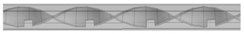
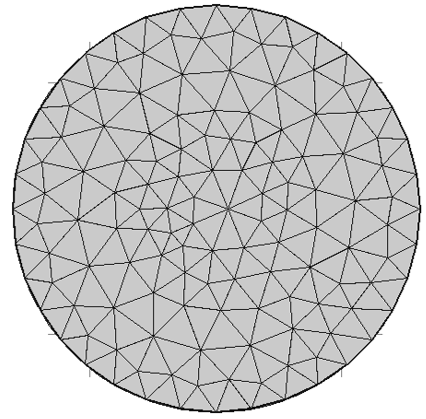
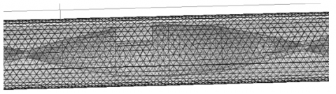
The full computational domain for the twist ratio 5.25 is shown in Figure 1. A modified rectangular-cut twisted tape insert of 960 mm inside a pipe of length 1000 mm, inner diameter of 26 mm and various cut dimensions are considered for simulation. Computational simulations have been performed to modify the mesh design until the desired outcomes are obtained. Fine mesh is considered for better simulation results. A high-performance computing system equipped with 16 GB of RAM (DDR3) and an Intel core i7 processor is used to conduct the numerical simulations. COMSOL Multiphysics, a FEM based software, is used [36, 37]. Figure 2 shows the full-length domain with inserts used for computation while the inlet mesh design and the complexity of its elements near the cuts on the insert are shown in Figures 3 and 4, respectively. Table 1 shows the comparison between various mesh elements.
Figure 1. Computational full domain
Figure 2. Computational full length insert domain
Figure 3. Computational inlet mesh design
Figure 4. Computational mesh design for inserts
Table 1. Distinct mesh elements comparison
|
Properties |
Plane Twist |
Cut-1 |
Cut-2 |
Cut-3 |
B. Salam Cut |
Plane Tube |
|
Tetrahedral elements |
87082 |
153947 |
105570 |
118158 |
13888 |
76293 |
|
Triangular elements |
18466 |
22294 |
19298 |
19938 |
21074 |
8728 |
|
Elements of edge |
2665 |
3127 |
2870 |
2918 |
3025 |
888 |
|
Elements of vertex |
204 |
283 |
264 |
264 |
271 |
8 |
|
Elements quality |
0.1657 |
0.1446 |
0.1239 |
0.1099 |
0.175 |
0.2318 |
|
Average element |
0.7587 |
0.7463 |
0.7465 |
0.7462 |
0.7462 |
0.7706 |
FEM is used for computational simulations. The purpose of this study is to use numerical simulation model to observe the heat transfer phenomenon in a tubular pipe of complex geometries. The k-ω non-isothermal turbulent flow model is considered for numerical simulation. The thickness of the tube is neglected while water is used as the working fluid in this simulation. Plane twist and tubes containing different cut configurations are used for this simulation.
4.1 Temperature profile
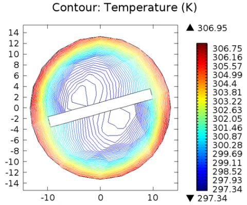
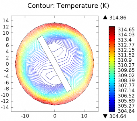
From Figure 5, the maximum contour temperature is observed to be 306.95 K at a position of 300 mm for plane twist configuration. At 600 mm and 900 mm positions, the maximum contour temperature increases to 314.86 K and 322.31 K, respectively.
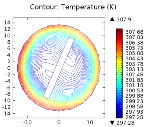
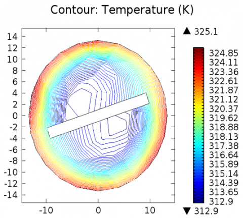
In presence of rectangular cut 1, as seen in Figure 6, the maximum contour temperature is observed to be 307.90 K at a position of 300 mm, which increases to 316.60 K and 325.10 K at positions 600 mm and 900 mm, respectively.
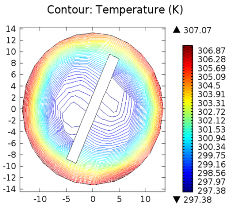
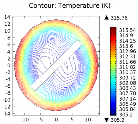
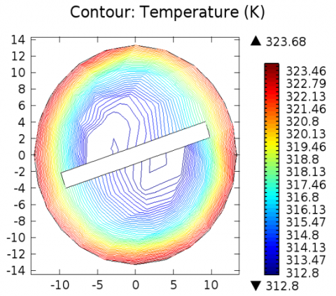
In presence of rectangular cut 2, as seen in Figure 7, the maximum contour temperature is observed to be 307.07 K at a position of 300 mm, which increases to 315.76 K and 323.68 K at positions 600 mm and 900 mm, respectively.
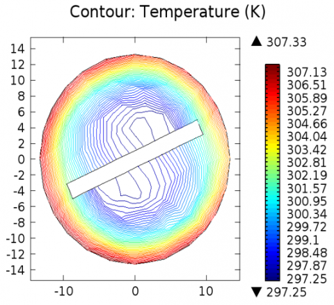
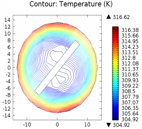
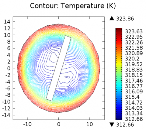
In presence of rectangular cut 3, as seen in Figure 8, the maximum contour temperature is observed to be 307.33K at a position of 300 mm, which increases to 316.62 K and 323.86 K at positions 600 mm and 900 mm, respectively.
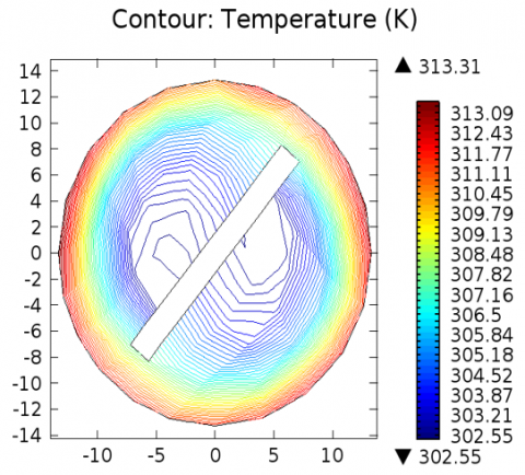
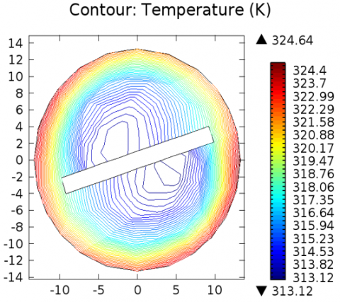
In presence of B. Salam cut, as seen in Figure 9, the maximum contour temperature is observed to be 313.31 K at a position of 300 mm, which increases to 315.93 K and 324.64 K at positions 600 mm and 900 mm, respectively.
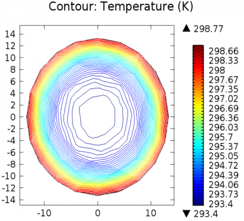
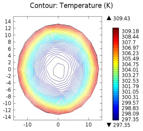
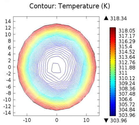
In absence of inserts, as seen in Figure 10, the maximum contour temperature is observed to be 298.77 K at a position of 300 mm, which increases to 309.43 K and 318.34 K at positions 600 mm and 900 mm, respectively.
Figure 5. Contour temperature profile for plane twist configuration at positions 300 mm, 600 mm, and 900 mm
Figure 6. Contour temperature profile for cut 1 configuration at positions 300 mm, 600 mm, and 900 mm
Figure 7. Contour temperature profile for cut 2 configuration at positions 300 mm, 600 mm, and 900 mm
Figure 8. Contour temperature profile for cut 3 configuration at positions 300 mm, 600 mm, and 900 mm
Figure 9. Contour temperature profile for B. Salam cut configuration at positions 300 mm, 600 mm, and 900 mm
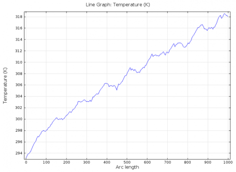
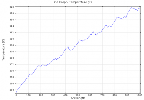
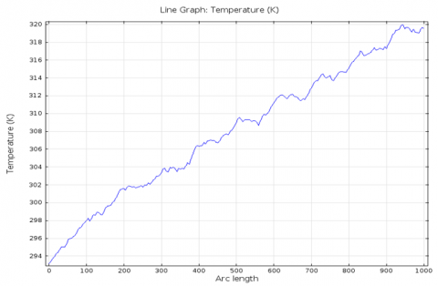
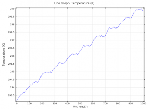
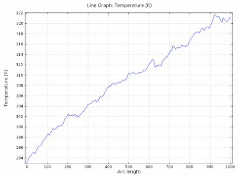
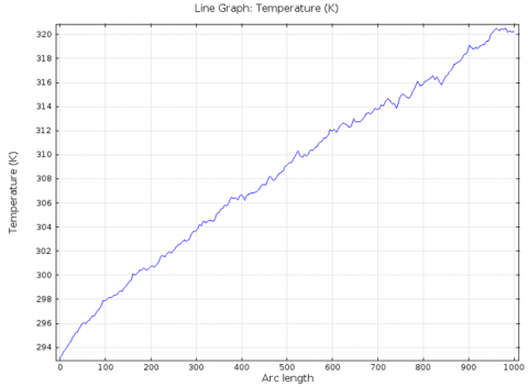
When the temperature of the fluid is measured along the length of the pipe, it shows an increasing pattern with or without cuts. For plane twist configuration, the maximum temperature of the fluid is observed to be 318.13 K near the outlet as seen in Figure 11(a). In presence of rectangular cuts 1, 2, 3 and B. Salam cut, as seen in Figures 11(b)-(e), the maximum temperature of the fluid is observed to be 320 K, 320 K, 299 K and almost 322 K respectively. In absence of inserts, the maximum temperature of the fluid reaches close to 320 K, as seen in Figure 11(f).
Figure 11. Temperature line graph
4.2 Vorticity profile
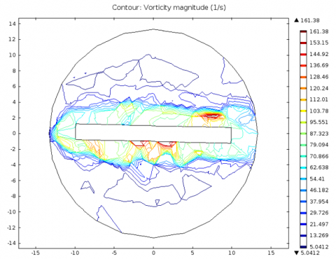
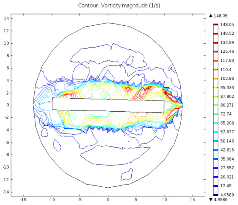
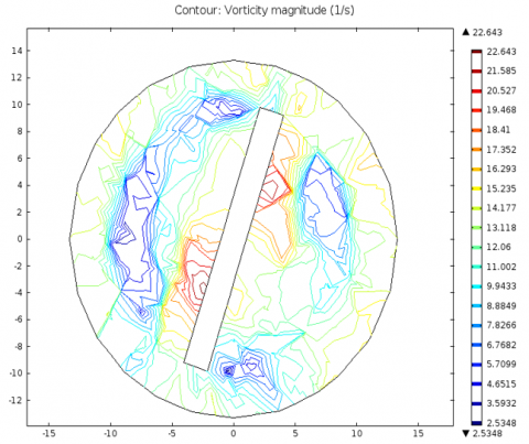
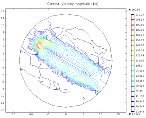
The vorticity profile is observed at a position of 900mm for plane twist, rectangular cuts 1, 2, 3 & B. Salam cut and plane tube as shown in Figure 12. The maximum vorticity at this position is found to be 21.694 (1/s) for plane tube, which increases to 136.93 (1/s) for plane twist configuration. The maximum vorticity changes to 165.56 (1/s), 161.38 (1/s), 148.05 (1/s) and 22.573 (1/s) in presence of rectangular cuts 1, 2, 3 and B. Salam cut respectively. The unexpected lower value of the maximum vorticity for B. Salam cut configuration is due to the absence of cut at the position of 900 mm. At the position of 960 mm of the insert of B. Salam cut configuration, as seen in Figure 13, the maximum vorticity is found to be 190.85 (1/s).
Figure 12. Vorticity magnitude at 900 mm
Figure 13. Vorticity magnitude of B. Salam cut at 960 mm
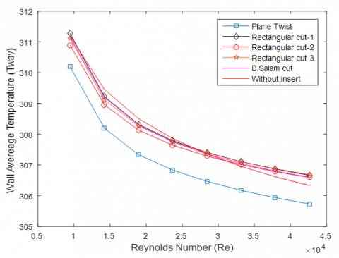
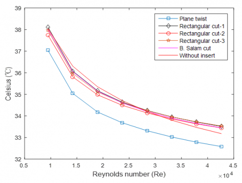
4.3 Average wall temperature profile
Figure 14 shows the average wall temperature distribution (Twav) for different geometrical configurations: Plane tube, plane twist, Rectangular Cut 1, 2, 3 and B. Salam cut. For all configurations, the wall temperature decreases consistently with increasing velocity, indicating more effective heat transfer as the velocity of fluid rises.
Figure 14. Average wall temperature in K
Figure 15. Average wall temperature in ℃
At a Reynold’s number of 9471, the wall temperature for the plane tube configuration is 311.19 K. It is 310.19 K for plane twist configuration, which increases to 311.27 K, 310.90 K, 311.11 K, 311.16 K in presence of rectangular cuts 1, 2, 3 and B. Salam cut respectively. Similar observation was noticed at a Reynold’s number of 42623, where the wall temperature of plane tube is found to be 306.33 K. A wall temperature of 305.73 K is found for the plane twist configuration which increases to 306.66 K, 306.59 K, 306.70 K and 306.60 K when rectangular cuts 1, 2, 3 and B. Salam cut were introduced respectively. This trend suggests that the rectangular cuts enhance the convective heat transfer process, with Rectangular Cut 1, 3 and B. Salam cut are among the highest wall temperatures across all velocities tested.
Figure 15 shows the average wall temperature distribution with the temperature in Celsius scale. The numerical results for B. Salam cut show the average wall temperature of 35.15-38.01℃ for Reynold’s number range of 9471-18943, which is similar to the experimental results of Salam et al. [33] of about 32-36℃ for Reynold’s number range of 10116-19070. Other cut configurations show similar pattern in wall temperature distribution.
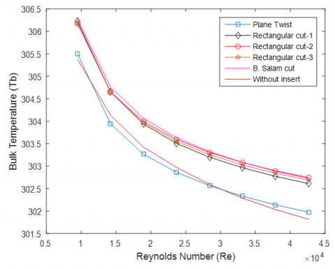
4.4 Bulk temperature profile
Figure 16 displays the bulk temperature profile for Reynold’s number ranging from 9471-42623 for plane twist, three different rectangular cut configurations with B. Salam cut and plane tube. The bulk temperature (Tb) decreases with increasing Reynold’s number for all configurations, indicating improved heat transfer as the velocity of fluid rises. At the Reynold’s number of 14207, the Bulk temperature is found to be 303.94 K for plane twist configuration. It increases in presence of rectangular cuts, with the highest temperature of 304.76 K obtained for B. Salam cut, which is higher than plane tube configuration (304.13 K).
Figure 16. Bulk temperature
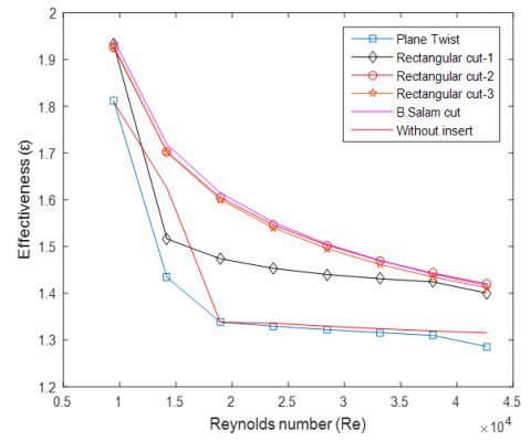
4.5 Effectiveness
Figure 17 shows the effectiveness profile for Reynold’s number ranging from 9471-42623 for plane twist, three different rectangular cut configurations with B. Salam cut and plane tube. The effectiveness decreases with increasing velocity for all configurations. At the Reynold’s number of 18943, the maximum effectiveness of 1.62 is achieved for B. Salam cut whereas the plane tube and plane twist configurations show an effectiveness of 1.34. Similar results are observed for other Reynold’s numbers.
Figure 17. Effectiveness
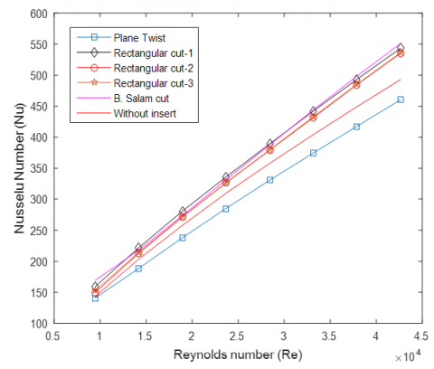
4.6 Nusselt number profile
Figure 18 displays the Nusselt number profile for Reynold’s number ranging from 9471-42623 for plane twist, three different rectangular cut configurations with B. Salam cut and plane tube. The Nusselt number increases consistently with Reynold’s number across all configurations, where the Plane Twist and Plane tube show the lowest Nusselt number compared to other configurations. The presence of rectangular cuts in twisted-tape inserts results in a significantly higher Nusselt number, with Rectangular Cut 1 and B. Salam cut having the maximum heat transfer rate for the studied Reynold’s number range. At a Reynold’s number of 9471, B. Salam cut shows the highest Nusselt number of 169.16 while the lowest of 140.76 was observed for the plane twist configuration. At a Reynold’s number of 18943, rectangular cut 1 shows the highest Nusselt number of 280.72 whereas the least of 237.85 was recorded for plane tube configuration.
Figure 18. Nusselt number profile
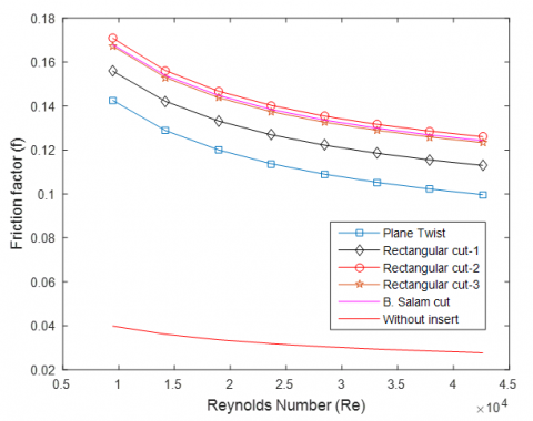
4.7 Friction factor
Figure 19 shows the variation of friction factor for Reynold’s number ranging from 9471-42623 for plane twist, three different rectangular cut configurations along with B. Salam cut and plane tube configuration. For all the configurations, the friction factor is observed to decrease with increasing Reynold’s number. At a Reynold’s number of 14207, the minimum friction factor is found to be 0.04 for plane tube while a maximum of 0.16 is observed for rectangular cut 2 while B. Salam cut shows 0.15. Similar results are seen for other Reynold’s numbers. These results are consistent with the experimental results by Salam et al. [33].
Figure 19. Friction factor profile
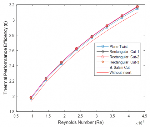
4.8 Thermal performance efficiency (TPE)
The thermal performance efficiency for Reynold’s number range 9471-42623 is shown in Figure 20. The B. Salam cut shows the highest TPE while the plane tube shows the lowest for the studied Reynold’s number range. In the experimental study by Salam et al. [33], the TPE is 1.8-2.2 for Reynold’s number 10116-19070. In this numerical simulation, the TPE is found to be 1.98-2.45 for B. Salam cut for Reynold’s number 9471-18943.
Figure 20. Thermal performance efficiency profile
The numerical simulations on a tubular pipe with inserts of various rectangular-cut configurations under uniform temperature conditions for Reynold’s number range 9471-42623 were conducted. The inclusion of inserts in a tubular pipe causes changes in the vorticity of the fluid in the tube, which results in variations in wall temperature, bulk temperature, effectiveness, Nusselt number and friction factor. The results show that:
This work is independent research that is not funded. The authors would like to thank the Department of Mathematics, Mahidol University, Bangkok-10400, Thailand, and the Department of Mathematics, Chittagong University of Engineering and Technology, Chittagong-4349 for their technical assistance.
|
l |
Length of the pipe |
|
D |
Diameter of the pipe |
|
CP |
Specific heat, J. kg-1. K-1 |
|
$\Delta P$ |
Pressure drop |
|
g |
gravitational acceleration, m.s-2 |
|
k |
Thermal conductivity, W.m-1. K-1 |
|
f |
Friction factor (-) |
|
Nu |
Nusselt number (-) |
|
Re |
Reynolds number (-) |
|
Ti |
Inlet temperature (K) |
|
To |
Outlet temperature (K) |
|
Tb |
Bulk temperature (K) |
|
Tw |
Wall temperature (K) |
|
Twav |
Average wall temperature (K) |
|
q |
Heat flux (W/m2) |
|
Q |
Amount of heat Joule(j) |
|
Greek symbols |
|
|
µ |
Dynamic viscosity, kg. m-1.s-1 |
|
$\omega$ |
Inverse time scale |
|
$\mu_T$ |
Turbulent viscosity |
|
$\varepsilon$ |
Effectiveness |
|
$\eta$ |
Thermal enhancement performance |
|
$\rho$ |
Density of water |
|
Subscripts |
|
|
p |
Plane tube |
|
t |
Twisted tape |
[1] Huber, C., Rosentritt, M., Strasser, T., Behr, M. (2021). Machine-Driven simulation of removing luting agent remnants from implant surfaces: An investigator-independent assessment of cleaning protocols. Journal of the Mechanical Behavior of Biomedical Materials, 121: 104584. https://doi.org/10.1016/j.jmbbm.2021.104584
[2] Penprase, B.E. (2018). The fourth industrial revolution and higher education. Higher Education in the Era of the Fourth Industrial Revolution, 10(1): 978-981. https://doi.org/10.1007/978-981-13-0194-0_9
[3] Uleanya, C. (2023). Scholarly discourse of the fourth industrial revolution (4IR) and education in Botswana: A scoping review. Education and Information Technologies, 28(3): 3249-3265. https://doi.org/10.1007/s10639-022-11298-9
[4] Khargotra, R., Kumar, R., Nadda, R., Dhingra, S., Alam, T., Dobrota, D., Chicea, A.L., András, K., Singh, T. (2023). A review of different twisted tape configurations used in heat exchanger and their impact on thermal performance of the system. Heliyon, 9(6): e16390. https://doi.org/10.1016/j.heliyon.2023.e16390
[5] Wagner, S. (2000). Computational Fluid Dynamics (CFD). In: Krause, E., Jäger, W. (eds) High Performance Computing in Science and Engineering ’99. Springer, Berlin, Heidelberg. https://doi.org/10.1007/978-3-642-59686-5_20
[6] Fadodun, O.G., Kaood, A., Hassan, M.A. (2022). Investigation of the entropy production rate of ferrosoferric oxide/water nanofluid in outward corrugated pipes using a two-Phase mixture model. International Journal of Thermal Sciences, 178: 107598. https://doi.org/10.1016/j.ijthermalsci.2022.107598
[7] Khalil, E.E., Kaood, A. (2021). Numerical investigation of thermal-Hydraulic characteristics for turbulent nanofluid flow in various conical double pipe heat exchangers. In AIAA Scitech 2021 Forum. Reston, Virginia: American Institute of Aeronautics and Astronautics, p. 2035. https://doi.org/10.2514/6.2021-2035
[8] Acherjee, S., Shahriar, M., Bhuyan, M.M., Deb, U.K. (2017). Enhancement of heat transfer in a u-loop circular tube with axial perforated inserts. Southeast Asian Journal of Sciences, 5(2): 126-136.
[9] Bhuyan, M.M., Deb, U.K., Shahriar, M., Acherjee, S. (2017). Simulation of heat transfer in a tubular U-Loop pipe using the rectangular inserts and without insert. AIP Conference Proceedings, 1851(1): 020011-020018. http://doi.org/10.1063/1.4984640
[10] Hossain, S., Deb, U.K., Rahman, K.A. (2015). The enhancement of heat transfer in a circular tube with insert and without insert by using the finite element method. Procedia Engineering, 105: 81-88. https://doi.org/10.1016/j.proeng.2015.05.010
[11] Ahamed, J.U., Wazed, M.A., Ahmed, S., Nukman, Y., Ya, T.T., Sarkar, M.A.R. (2011). Enhancement and prediction of heat transfer rate in turbulent flow through tube with perforated twisted tape inserts: A new correlation. ASME Journal of Heat Transfer, 133: 041903-1. https://doi.org/10.1115/1.4002635
[12] Faridi Khouzestani, R., Ghafouri, A. (2020). Numerical study on heat transfer and nanofluid flow in pipes fitted with different dimpled spiral center plate. SN Applied Sciences, 2(2): 298. https://doi.org/10.1007/s42452-020-2084-x
[13] Eiamsa-ard, P., Wongcharee, K., Kunnarak, K., Kumar, M., Eiamsa-ard, S., Pimsarn, M. (2022). Heat transfer characteristics of a swirling impinging air jet emerging from a triple spiral-Corrugated nozzle with a twisted tape installed. Thermophysics and Aeromechanics, 29(4): 519-530. https://doi.org/10.1134/S0869864322040059
[14] Nashee, S.R., Ibrahim, Z.A., Kamil, D.J. (2024). Numerical investigation of flow in vertical rectangular channels equipped with three different obstacles shape. AIP Conference Proceedings, 3122(1): 100002. https://doi.org/10.1063/5.0216016
[15] Pourhedayat, S., Khorasani, S., Dizaji, H.S. (2019). A comprehensive analysis and empirical correlations for Nusselt number, friction factor and exergy destruction of helical tube equipped with spring-wire. International Journal of Thermal Sciences, 145: 106050. https://doi.org/10.1016/j.ijthermalsci.2019.106050
[16] Anika, O.I., Bhuyan, M.M., Deb, U.K. (2024). Enhancement of heat transfer in a pipe fitted with rectangular cut twisted tape inserts. International Journal of Heat and Technology, 42(5): 1501-1506. https://doi.org/10.18280/ijht.420502
[17] Bhuyan, M.M., Surja, M.C., Deb, U.K. (2024). Effect of twist ratios on heat transfer for circular-Cut twisted tape inserts in U-Shaped pipe. International Journal of Heat & Technology, 42(6): 1952-1962. https://doi.org/10.18280/ijht.420612
[18] Murugesan, P., Mayilsamy, K., Suresh, S., Srinivasan, P.S.S. (2011). Heat transfer and pressure drop characteristics in a circular tube fitted with and without V-cut twisted tape insert. International Communications in Heat and Mass Transfer, 38(3): 329-334. https://doi.org/10.1016/j.icheatmasstransfer.2010.11.010
[19] Nashee, S.R. (2024). Numerical simulation of heat transfer enhancement of a heat exchanger tube fitted with single and double-Cut twisted tapes. International Journal of Heat and Technology, 42(3): 1003-1010. https://doi.org/10.18280/ijht.420327
[20] Chowdhury, M.K., Bhuyan, M.M., Deb, U.K. (2019). Augmentation of heat transfer in pipe flow using plane twisted tape inserts for different twist ratios. Energy and Power Engineering, 11(9): 342-354. https://doi.org/10.4236/epe.2019.119022
[21] Bhuiya, M.M.K., Ahamed, J.U., Sarkar, M.A.R., Salam, B., Sayem, A.S.M., Rahman, A. (2014). Performance of turbulent flow heat transfer through a tube with perforated strip inserts. Heat Transfer Engineering, 35(1): 43-52. https://doi.org/10.1080/01457632.2013.810449
[22] Saysroy, A., Eiamsa-ard, S. (2017). Periodically fully-Developed heat and fluid flow behaviors in a turbulent tube flow with square-Cut twisted tape inserts. Applied Thermal Engineering, 112: 895-910. https://doi.org/10.1016/j.applthermaleng.2016.10.154
[23] Eiamsa-Ard, S., Thianpong, C., Eiamsa-Ard, P., Promvonge, P. (2009). Convective heat transfer in a circular tube with short-Length twisted tape insert. International Communications in Heat and Mass Transfer, 36(4): 365-371. https://doi.org/10.1016/j.icheatmasstransfer.2009.01.006
[24] Bhuyan, M.M., Deb, U.K., Shahriar, M., Acherjee, S. (2017). Simulation of heat transfer in a tubular pipe using different twisted tape inserts. Open Journal of Fluid Dynamics, 7(3): 397-409. https://doi.org/10.4236/ojfd.2017.73027
[25] Zhang, T., Su, M., Zhang, H., Liu, C., Ouyang, X. (2024). Design and simulation of a new type of fin-and-tube heat exchanger with trapezoidal slit fins. Case Studies in Thermal Engineering, 59: 104604. https://doi.org/10.1016/j.csite.2024.104604
[26] Shakir, R. (2023). Prediction study of the boiling flow of heat transfer in an array of in-line micro-pin-fins heat sink. American Institute of Physics Conference Series, 2845(1): 060003. https://doi.org/10.1063/5.0157017
[27] Fouda, A., Nada, S.A., Elattar, H.F., Refaey, H.A., Bin-Mahfouz, A.S. (2018). Thermal performance modeling of turbulent flow in multi tube in tube helically coiled heat exchangers. International Journal of Mechanical Sciences, 135: 621-638. https://doi.org/10.1016/j.ijmecsci.2017.12.015
[28] Hasanpour, A., Farhadi, M., Sedighi, K. (2016). Experimental heat transfer and pressure drop study on typical, perforated, V-cut and U-cut twisted tapes in a helically corrugated heat exchanger. International Communications in Heat and Mass Transfer, 71: 126-136. https://doi.org/10.1016/j.icheatmasstransfer.2015.12.032
[29] Acherjee, S., Deb, U.K., Bhuyan, M.M. (2020). The effect of the angle of perforation on perforated inserts in a pipe flow for heat transfer analysis. Mathematics and Computers in Simulation, 171: 306-314. https://doi.org/10.1016/j.matcom.2019.10.003
[30] Marzouk, S.A., Almehmadi, F.A., Aljabr, A., Sharaf, M.A. (2024). Numerical and experimental investigation of heat transfer enhancement in double tube heat exchanger using nail rod inserts. Scientific Reports, 14(1): 9637. https://doi.org/10.1038/s41598-024-59085-5
[31] Sharaf, M.A., Marzouk, S.A., Aljabr, A., Almehmadi, F. A., Alam, T., Teklemariyem, D.A. (2024). Effects of multi-spring wires on hydrothermal performance of double tube heat exchanger. Case Studies in Thermal Engineering, 60: 104689. https://doi.org/10.1016/j.csite.2024.104689
[32] Poblador-Ibanez, J., Sirignano, W.A., Hussain, F. (2024). Vorticity dynamics in transcritical liquid jet breakup. Journal of Fluid Mechanics, 978: A6. https://doi.org/10.1017/jfm.2023.961
[33] Salam, B., Biswas, S., Saha, S., Bhuiya, M.M.K. (2013). Heat transfer enhancement in a tube using rectangular-Cut twisted tape insert. Procedia Engineering, 56: 96-103. https://doi.org/10.1016/j.proeng.2013.03.094
[34] Nakhchi, M.E., Esfahani, J.A. (2019). Numerical investigation of rectangular-Cut twisted tape insert on performance improvement of heat exchangers. International Journal of Thermal Sciences, 138: 75-83. https://doi.org/10.1016/j.ijthermalsci.2018.12.039
[35] Nashee, S.R. (2024). Numerical simulation of heat transfer enhancement of a heat exchanger tube fitted with single and double-Cut twisted tapes. International Journal of Heat and Technology, 42: 1003-1010. https://doi.org/10.18280/ijht.420327
[36] Reddy, J.N. (1993). An introduction to the finite element method. New York. Third Edition, McGraw-Hill, 27(14).
[37] www.comsol.com, accessed on Dec. 20, 2024.
[38] Menter, F.R. (1994). Two-equation eddy-viscosity turbulence models for engineering applications. AIAA Journal, 32(8): 1598-1605. https://doi.org/10.2514/3.12149
[39] Wilcox, D.C. (1994). Simulation of transition with a two-Equation turbulence model. AIAA Journal, 32(2): 247-255. https://doi.org/10.2514/3.59994
[40] Bhuiya. M.M.K., Chowdhury M.S., Islam M., Ahmed J.U., Khan M., Sarker M., Saha M. (2012). Heat transfer performance evaluation fobhuiyar turbulent flow through a tube with twisted wire brush insert. International Communications in Heat and Mass Transfer, 39(10): 1505-1512. https://doi.org/10.1016/j.icheatmasstransfer.2012.10.005