Mohammed Wahody Eraiby*![]() | Duraid F. Mak
| Duraid F. Mak![]()
© 2025 The authors. This article is published by IIETA and is licensed under the CC BY 4.0 license (http://creativecommons.org/licenses/by/4.0/).
OPEN ACCESS
In recent decades, the Kalina cycle (KC) has occupied an important position in exploiting waste heat in many industry applications for cogenerating power and cooling. The KC is enhanced by adding a heat exchanger that is installed after the condenser. This paper is a theoretical analysis of the temperature effect of turbine input on the state of binary solution (ammonia-water) at the exit region of the condenser. The examining range of temperature (180-190℃) is at a constant maximum pressure of 3500 kPa and a dryness fraction of about 0.3; the range of net power output is 25-250 kW, with a varying minimum pressure range from 10 to 90 kPa. The outcome shows that decreasing the turbine inlet temperature (TIT) reduces the working fluid temperature beyond the condenser (T4), consequently enhancing the cooling output at an optimum minimum pressure of 50 kPa and TIT=180℃, the condenser exit temperature (CET) drops to about -3.3℃, which gives a high cooling capacity of 420.7 kW at 250 kW output turbine power. On the other hand, when TIT=190℃, T4 drops to 5.06℃, which gives the lowest cooling capacity of 19.66 kW at 25 kW output turbine power.
Kalina cycle, waste heat recovery, Cogeneration of power and refrigeration, Turbine inlet temperature, Ammonia-water working fluid
In the current era with increased energy use, as the world's population continues to rise and fossil energy sources continue to run out, it is now essential to use resources as efficiently as possible without harming the environment. Thus, producing electricity and cooling from various heat sources, like waste incineration, solar and geothermal springs, and industrial waste heat, is challenging for humanity. The most important candidate for using this waste heat energy is the Kalina cycle (KC). Seckin [1] focused on a coupled system that consists of the KC, which uses ammonia solution for power, and the ejector refrigeration cycle (ERC), which utilizes R-134a for cooling. The increase of turbine input temperature (TIT) on the energy efficiency increased by 7%, but the exergy efficiency declined by 41%. However, the refrigeration generation of ERC operating conditions remains unaffected by the increase in temperature (TIT). Amorim et al. [2] investigated a KC with modified components, which included a superheater before the expander and a regenerator before the throttling valve, used insolation heat as a resource for low-temperature heating from 90 to 120℃. The outcomes indicate the suggested cycle improves efficiency by approximately 7.4% compared to the original cycle. Abam et al. [3] studied a binary generation system (KLPCCs). It has a top Kalina cycle (TPC) that uses NH₃-H₂O to make electricity and a bottom cycle that uses a vapor absorption cooling system (VAB) and LiBr as the working fluid. It showed that when the TIT goes from 145℃ to 185℃, the gross power of the turbine goes up by 21.62%, with about 373.7 kW being the highest extract. Cao et al. [4] idea was to add an absorption refrigeration cycle to the KC so the heat from the weak mixture could be used before the throttle valve. The outcomes indicate that raising the TIT from 105 to 130℃ augments the gross power and second law efficiency while decreasing the energy efficiency. Akimoto et al. [5] studied a suggestion to produce power in multiple stages. If the heat lost in the first KC is not enough to power another KC, then use an absorption heat pump (AHP) to make energy for KC 2 again, and so on in a chain. The results indicate an 81% increase in gross power for (AHP + KC) compared to the traditional KC system, while the KC + AHP + KC system outperformed the others at a heat source temperature of 353 K. Eller et al. [6] studied a new proposal for KC, which aims to exploit waste heat between 200℃ and 400℃. The thermal efficiency of the KC system was raised by using a new pair of alcohol/alcohol mixtures instead of the main ammonia solution. The growth rate in thermal efficiency was about 16%. Parvathy and Varghese [7] studied involved adjusting the KC by utilizing two turbines and reheating in between to improve electricity production. The outcomes indicate that 28.7% is the highest efficiency achieved at an intermediate pressure of 35 bar. The suggested dual turbine system's efficiency gain over the original KC can reach 4.04%. Nassir and Shahad [8] studied a change to enhance the efficiency of the original KC. A heat exchanger is inserted between the expansion valve and the separator to complete the modification. The high-temperature, saturated liquid that leaves the separator is utilized to re-heat the ammonia solution that leaves the pumper. The outcomes indicate the recommended cycle efficiency is approximately 27.8% greater than the net power and approximately 33.6% higher than the original cycle. Ahmad and Rahman [9] studied a proposal to increase the use of collector insolation heat energy through the KC. The research indicates when the separator inlet temperature increases, the turbine power extracted increases, and the proposed system's enhancement is between 30% and 50% of plant efficiencies. Nassir and Shahad [10] studied the OKCS illustrated in Figure 1 and suggested two adjustments to the basic Kalina cycle (KCS). The first adjustment (MKCS1) is to add a heat swap (HE1) before the throttle valve, and the second adjustment (MKCS2) is to add a second heat swap (HE2) between the turbine and mixer. The KC uses an ammonia solution. The outcomes show performance improvement; the maximum energy efficiency for the basic KC, first adjustment, and second adjustment is 9%, 13%, and 19%, respectively. Qu et al. [11] The suggestion was made to integrate KC, which uses an absorption chiller to cool the work solution after its turbine, with concentrating photovoltaic cells, which have a waste heat of approximately 60-70℃. The thermal competence of a Kalina cycle with chilling has the possibility of increasing by 2-3% relative to the original Kalina cycle. Also, the insolation heat-to-electricity efficiency is up to 24%, but the photovoltaic efficiency is about 4.2% without Kalina chilling. Zhang et al. [12] studied a Kalina cycle as cogeneration (PPR-KC) shows high efficiency with a refrigeration subsystem aligned with the power generation circuit. The results indicated increased enthalpy across the turbine and output power. The whole power extraction efficiency reaches 27.2%. da Costa Horta et al. [13] investigated two Kalina cycles, the original KCS1 and the adjustment KCS34, to restore the rejected heat in the cement plants in Brazil. uses a superheater with varying temperatures across it (ΔT) before the turbine to improve the system. Results show that the gross power of the KCS1 is greater than that of the KCS34. Wang et al. [14] studied a solar collection with a storage circle as a heat resource for the KC, with a test design temperature of 120℃. Examined the effect of temperature with several methods of thermal analysis. It is indicated that when the resource temperature is lower than planned, the gross power extracted with the changing pressure-controlling method declines. If the resource temperature is higher than planned, the gross power would rise with the modified changing pressure controlling method. Liu et al. [15] studied a combined system that includes an aider cycle represented by an absorption chiller using a LiBr/H₂O binary mixture as a cooling source for a Kalina cycle. The outcome shows that optimum turbine input pressures are acquired at 32-33 bar, which occurs at the optimal thermal efficiency of 16.78%. Seçkin [16] looked into how to combine a KC to make electricity with an ejector refrigeration cycle (ERC) based on R134a to produce cooling. Show that with the evaporator temperature increasing from 0 to 10℃, the net power will increase from 75 to 100 kW, the performance coefficient (COP) will increase from 0.25 to 0.6, and the cooling capacity will increase from 30 to 55 kW. Aslan et al. [17] concluded that a TIT significantly influences the performance of the Kalina cycle. Higher TITs generally lead to an improved performance cycle. At a temperature of the entrance turbine of about 430℃, the Kalina cycle achieved maximum net power production of 389.44 kW, thermal efficiency of 33.86%, and exergy efficiency of 68.96%. Khanmohammadi et al. [18] studied the integration of Kalina cycle, an insolation unit, a desalination unit (reverse osmosis), and a thermoelectric generator (TEG) system. The outcome shows that when the DNI temperature increases, the power extracted by the TEG also rises. Additionally, there is an increase in gross extract power and drinking water output by approximately 6.1% and 3.48%, respectively. This work modifies the original Kalina cycle to produce electricity from the turbine and obtain cooling by adding a heat exchanger between the condenser and the pump. In this theoretical experiment, the TIT ranged from 180 to 190℃, and the ammonia concentration matched. The dryness fraction stayed at 0.3; the maximum pressure stayed at 3500 kPa; and the minimum pressure at the exit of the turbine changed from 10 kPa to 90 kPa in 20 kPa steps.
2.1 Principles of the adjusted Kalina cycle
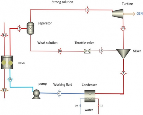
In the modified Kalina cycle (MKCS) for cogeneration, as shown in Figure 2, a heat exchanger is used to obtain air cooling and power from the turbine. The modification cycle includes heat restore vapor generation (HRVG), a separator, a turbine, a throttle valve, a mixer (absorber), a condenser, a heat exchanger, and a working fluid pump. The evaporator temperature range selected for this analysis is 180℃ to 190℃. The binary ammonia-water mixture of the cycle absorbs waste heat at (HRVG), transitioning into the wet-vapor phase (region 7). It then enters the vapor-liquid separator at high temperatures and pressure. It is divided into saturated vapor as a strong solution of the mixture (region 1) and saturated liquid as a weak solution of the mixture (region 8). The saturated vapor (region 1) is directed to the turbine (expander), which extracts work from the strong solution and expands it to the turbine’s exhaust (region 2). Meanwhile, the saturated liquid (region 8) enters the throttle valve, where its pressure and temperature are reduced in the isenthalpic process, reaching position (region 9); then both the vapor stream from the turbine exit (region 2) and the liquid stream from the throttle valve exit (region 9) are blended in the mixer (absorber) to produce a wet-vapor working fluid again, with a dryness fraction of 0.44 at the state (region 3). and the component ammonia-water mixture at state (3) is condensed in the condenser to form a saturated liquid (region 4) with a low-temperature and low-pressure working fluid, which in turn enters a heat exchanger to generate cooling for the required zone. The working fluid leaves the heat exchanger (HE) as a saturated liquid in a state (region 4). It is drawn by the pump, which moves it to a state (region 5) and then transfers it to a state (region 7) after it has gained heat again at HRVG.
Figure 2. Modified Kalina cycle system (MKCS)
2.2 Mathematical model and properties
Each component in the model, which is based on Kalina cycle, can be considered a system unit working on equations of energy and mass conservation. The mathematical calculation formulas for each part of Kalina cycle are clear in Table 1. To calculate all the thermodynamic properties of a binary solution (ammonia/water) at each point of the cycle, it is required to know at least the main three parameters, for example, pressure, temperature, and concentration. Additionally, to employ and ease the mathematical software, some hypotheses are made as follows:
1. The cycle works in a steady state, disregarding potential energy and kinetic energy.
2. The loss of heat to the outside in all parts of the cycle is ignored.
3. The leaking of mixture solution and pressure drop in tubes are ignored, whereas the pressure drop in some parts is impossible to neglect.
4. The value of the isentropic efficiency for both the turbine and the pump is considered to be 85% and 95%, consecutively.
5. The ammonia solution at the condenser output is a saturated liquid, DF=0.
6. The flow through the throttle valve is a constant-enthalpy process.
7. The strong solution at the turbine entrance with maximum pressure is dry saturated vapor, DF=1.
8. The weak solution at the throttling valve entrance with maximum pressure is a saturated liquid, DF=0.
9. The ammonia solution at the exit of the heat restore vapor generator (HRVG) is in a wet vapor state at constant pressure.
10. The effectiveness of heat recovery, vapor generator, and condensers is equal (ϵ=1).
11. The ammonia and water used are pure fluids.
12. The hot gas temperature measured in the flue is 190℃, as a heat source.
13. The ammonia solution temperature at the heat exchanger (HE) outlet is about 35℃.
14. The input parameters in each component of the MKCS can be confirmed, as shown in Table 2.
Table 1. Mathematical calculation equations for the modified Kalina cycle (MKCS) [19]
|
Project |
Equation |
No. |
|
Energy conservation |
$\Delta_{ {out }}^{ {in }} \sum_i^n Q_i=0$ |
(1) |
|
Mass conservation |
$\Delta_{ {out }}^{ {in }} \sum_i m_i=0$ |
(2) |
|
Total mass of working fluid |
$m_{t o t}=m_7=m_3=m_4=m_{\dot{4}}=m_5$ |
(3) |
|
HRVG |
$\begin{aligned} m_{g e n} \cdot\left(h_{12}-h_{14}\right) & =m_{t o t} \cdot\left(h_7\right.\left.-h_5\right)\end{aligned}$ |
(4) |
|
Separator |
$m_{ {tot }}=m_1+m_8$ |
(5) |
|
$m_7 \cdot x_7=m_1 \cdot x_1+m_8 \cdot x_8$ |
(6) |
|
|
$m_7 \cdot h_7=m_1 \cdot h_1+m_8 \cdot h_8$ |
(7) |
|
|
Turbine |
$W_{t u r}=m_1 \cdot\left(h_1-h_2\right) \cdot\left(\eta_t\right)_{ {isent }}$ |
(8) |
|
$\left(\eta_t\right)_{{isent }}=\frac{\left(h_1-h_2\right)}{\left(h_1-h_{2 s}\right)}$ |
(9) |
|
|
Condenser |
$Q_{ {con }}=m_3 \cdot\left(h_3-h_4\right)$ |
(10) |
|
Pump |
$s_5=s_{\dot{4}}$ |
(11) |
|
$W_{{pump }}=\frac{v_{\dot{4}} \cdot\left(P_5-P_{\dot{4}}\right) \cdot 100}{m_{\dot{4}} \cdot\left(\eta_{ {Pump }}\right)_{ {isent }}}$ |
(12) |
|
|
Mixer (Absorber) |
$m_3=m_2+m_9$ |
(13) |
|
$m_3 \cdot x_3=m_2 \cdot x_2+m_9 \cdot x_9$ |
(14) |
|
|
$m_3 \cdot h_3=m_2 \cdot h_2+m_9 \cdot h_9$ |
(15) |
|
|
Thermal efficiency |
$Q_{i n}=m_{g e n} \cdot\left(h_{12}-h_{14}\right)$ |
(16) |
|
$W_{ {net }}=W_{ {tur }}-W_{{pump }}$ |
(17) |
|
|
$\eta_{t h}=\frac{W_{n e t}}{Q_{i n}}$ |
(18) |
|
|
Exergy efficiency |
$E_{\text {in }}^{\cdot}=m_{ {tot }} \cdot\left(h_5-T_{\circ} \cdot s_5\right)$ |
(19) |
|
$E_{ {out }}^{\cdot}=m_{ {tot }} \cdot\left(h_7-T_0 \cdot s_7\right)$ |
(20) |
|
|
$\eta_{ {exe }}=\frac{W_{ {net }}}{\left(E_{ {in }}^{\cdot}-E_{{out }}^{\cdot}\right)}$ |
(21) |
Table 2. The boundary conditions of simulation for the modified Kalina cycle (MKCS)
|
Item |
Parameters |
|
Turbine inlet temperature (TIT) range |
180-190℃ |
|
Turbine outlet pressure range |
10-90 kPa |
|
Ambient temperature |
25℃ |
|
Ambient pressure |
101.30 kPa |
|
Turbine input pressure |
3500 kPa |
|
Dryness Fraction |
0.3 |
|
Ammonia concentration of the working fluid |
0.72-0.64 (kgNH3/kgmixture) |
|
Turbine's isentropic efficiency |
85% |
|
Pump efficiency |
95% |
|
Cooling temperature required |
19℃ |
2.2.1 Model validation
A model validation of this work by comparison with the experimental study of Srinivas et al. [20] has been conducted. considered simple Kalina cycle in the study of Srinivas et al. [20] is nearest to current work model components, under the same input operation conditions such as the hot gases, the TIT, the turbine input ammonia concentration, and the separator inlet dryness fraction, 175℃, 160℃, 0.85, and 0.1569, respectively. Also, the maximum and minimum pressures are 3767 kPa and 258 kPa, respectively. Table 3 displays the findings from both the current study and the previous study [20]. This validation data can come to a good agreement. Consequently, the current work's simulation model is suitable for thermodynamic analysis.
Table 3. Validation results with Srinivas et al. [20]
|
Case |
Ref. [20] |
Present Study |
Deviation (%) |
|
$Q_{\text {in }}^{\cdot}$ [kW] |
1366.358 |
1384 |
-1.274710983 |
|
$Q_{\text {rej }}^{\cdot}$ [kW] |
1254.551 |
1276 |
-1.680956113 |
|
$W_{\text {net }}^{\cdot}$ [kW] |
86.6457 |
90.01 |
-3.737695812 |
|
Cycle/Eff. % $\eta_{\text {th }}$ |
6.341361 |
6.503 |
-2.485606643 |
2.3 Thermodynamic analysis
To assess the effect of a few critical parameters on the system's performance, a parametric analysis of the suggested system should be conducted. like the TIT, and the Turbine outlet Pressure (TOP). One parameter is changed while the others are held constant to examine the impacts of temperature and pressure.
1- The maintaining pressure constant method: keeping the turbine outlet pressure constant by varying the temperature effect of the turbine entrance (TIT), when Kalina cycle is working under the same other circumstance such as the ammonia concentration and dryness fraction [14].
2- The change pressure controlling method: varies the turbine outlet pressure while keeping the temperature effect of the turbine entrance (TIT) constant when Kalina cycle is working under the same other circumstance such as the ammonia concentration and dryness fraction [14].
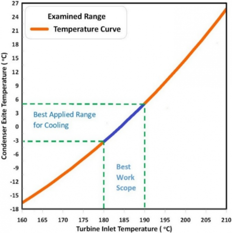
Beginning, a large-scale test was conducted for the TIT on the system to select the appropriate and realistic scope, as shown in Figure 3. It was found that whenever the TIT increased above 190℃, the condenser outlet temperature (T4) exceeded 5.06℃, and thus the actual benefit of temperature required for the working fluid used for cooling purposes was lost. And whenever (TIT) decreased below 180℃, T4 decreased below -3.3℃ and thus deviated from the intended purpose.
Figure 3. Best work scope of TIT for this research
The computer model for the modified cycle was operated, focused on valuing the performance of the combined cycle to produce electricity and cooling. The thermodynamic analysis was conducted, which consisted of the energy analysis, the exergy analysis, and the parametric analysis of the suggested model. The sample results obtained are shown in Table 4 below.
Table 4. Sample case, of the temperature effect of the turbine entrance (TIT) on system performance
|
TIT (℃) |
Condenser Exite Temperature T4 (℃) |
Qrload (kW) |
$\eta_{\text {th }}$ % |
$\eta_{\text {exe}}$ % |
|
180 |
-3.30 |
41.04 |
14.23 |
51.93 |
|
182 |
-1.72 |
39.41 |
14.06 |
50.92 |
|
184 |
-0.09 |
37.70 |
13.90 |
49.96 |
|
186 |
1.57 |
36.00 |
13.71 |
48.95 |
|
188 |
3.29 |
34.20 |
13.54 |
48.01 |
|
190 |
5.06 |
32.29 |
13.39 |
47.17 |
3.1 Effect of TIT on thermal efficiency
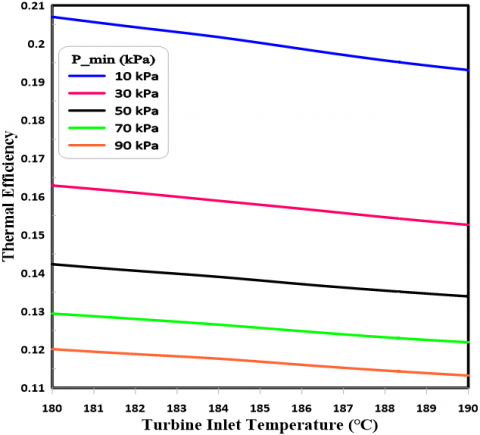
The graph in Figure 4 shows how the TIT influences the MKCS's thermal efficiency under the examined conditions with gross power requirements. It is evident that a rise in the TIT results in a rise in the cycle's heat gain, leading to a decline in thermal efficiency. Additionally, a rise in turbine outlet pressure causes a reduction in the enthalpy difference across the turbine. Overall, the rise in these two parameters results in a decline in thermal efficiency in this study. The highest thermal efficiency recorded is 20.7% at 10 kPa and 180℃, whereas the lowest value is 11.32% at 90 kPa 190℃.
Figure 4. Impact of TIT on the thermal efficiency of MKCS
3.2 Effect of TIT on exergy efficiency
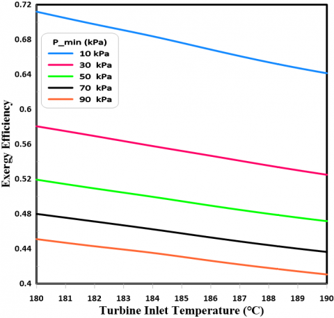
Figure 5 shows the effect of TIT on the exergy efficiency of MKCS. With gross power required, under the same operating conditions, it can be noted that TIT harms the exergy efficiency of the suggested system because of a rise in exergy destroyed. The highest exergy efficiency is 71.2% at 10 kPa and 180℃, while the lowest value is 41% at 90 kPa and 190℃.
Figure 5. Impact of TIT on the exergy efficiency of MKCS
3.3 Effect of TIT on cooling capacity
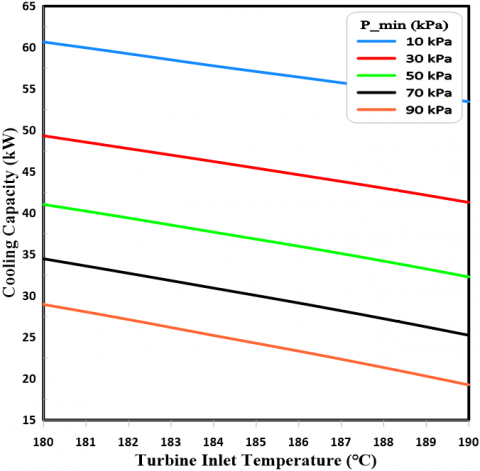
Figure 6 illustrates the impact of the TIT on the cooling capacity of the MKCS. When the TIT rises, it leads to an increasing condenser exit temperature (T4). As such, the cooling capacity will decrease. When the minimum pressure declines, both the turbine outlet temperature (T2) and the condenser exit temperature (T4) decrease, leading to an increase in the cooling output. The highest cooling capacity is 60.67 kW at 10 kPa and 180℃, while the lowest value is 19.24 kW at 90 kPa and 190℃.
Figure 6. Impact of TIT on the cooling capacity of MKCS
3.4 Effect TIT on condenser exit temperature
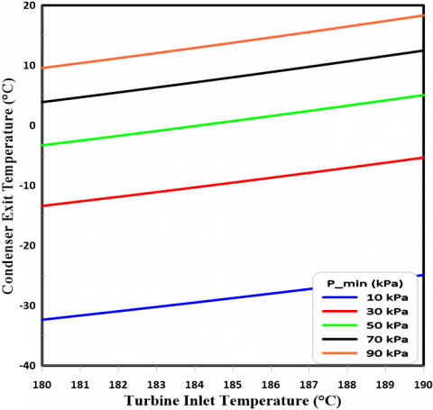
The graph in Figure 7 shows how TIT affects the working fluid's condenser exit temperature (T4) within the MKCS study limits. As the TIT increases, the condenser exit temperature (T4) rises due to a decrease in the ammonia concentration of water. On the other hand, the condenser exit temperature (T4) falls as the minimum pressure (TOP) of the modified Kalina cycle (MKCS) decreases. The lowest temperature (T4) is -32.35℃ at 10 kPa and 180℃, and the highest temperature is 18.32℃ (90 kPa).
Figure 7. Impact of TIT on exit condenser temperature (T4) of MKCS
Figure 8. Impact of turbine outlet pressure (TOP) on the exit condenser temperature (T4) of MKCS
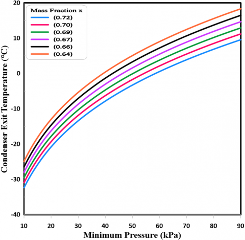
3.5 Effect TOP on condenser exit temperature
Figure 8 illuminates the impact of turbine outlet pressure (TOP) on the working fluid's condenser exit temperature (T4) under the examined operation conditions. When the turbine output pressure goes down, the stroke expansion goes up. This causes the turbine outlet temperature (T2) to go down. This will also result in a decrease in the condenser exit temperature (T4). It is better for the cooling process when the exit condenser temperature (T4) is lower. However, as the ammonia concentration rises in water, the condenser exit temperature (T4) decreases. That means the cooling capacity increases as the condenser exit temperature decreases. The lowest condenser exit temperature is -32.35℃ at 10 kPa and an ammonia concentration of about 0.72, while the highest value of (T4) is 18.32℃ at 90 kPa and an ammonia concentration of about 0.64.
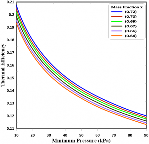
3.6 Effect TOP on thermal efficiency
Figure 9 shows, for different amounts of ammonia, how the turbine output pressure (TOP) affects its thermal efficiency. A high turbine outlet pressure decreases efficiency due to a lower turbine enthalpy difference. These efficiencies increase with higher ammonia concentrations due to the rise in the rate of mass flow. The greatest thermal efficiency is 20.7% at 10 kPa, and the ammonia concentration is about 0.72; the least value is 11.32% at 90 kPa, and the ammonia concentration is about 0.64.
Figure 9. Impact of turbine outlet pressure (TOP) on the thermal efficiency of MKCS
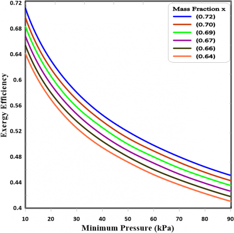
3.7 Effect TOP on exergy efficiency
Figure 10 illuminates the influence of turbine output pressure (TOP) on the exergy efficiency of MKCS for varying ammonia concentrations. With increasing TOP, the enthalpy difference through the turbine power decreases. Consequently, the rise in exergy destruction leads to a decline in exergy efficiency. Also, the rise in ammonia concentration results in a rise in the mass flow rate and a rise in power extraction, thus improving exergy efficiency. The biggest exergy efficiency is 71.2% at 10 kPa, and the ammonia concentration is about 0.72, while the smallest value is 41% at 90 kPa, and the ammonia concentration is about 0.64.
Figure 10. Impact of turbine outlet pressure (TOP) on exergy efficiency of MKCS
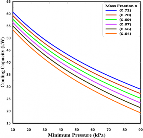
3.8 Effect TOP on cooling capacity
It's also worth mentioning that a drop in the turbine outlet pressure (TOP) improves the cooling ability of the proposed system, as seen in Figure 11. This is because the condenser exit temperature goes down, and things get better as the ammonia concentration goes up. Figure 11 illustrates this. The biggest cooling capacity is 60.67 kW at 10 kPa, and the ammonia concentration is about 0.72, while the lowest value is 19.24 kW at 90 kPa, and the ammonia concentration is about 0.64.
Figure 11. Impact of turbine outlet pressure (TOP) on cooling capacity of MKCS
1. A rise in the TIT will increase the heat gain of the cycle; consequently, there will be a drop in energy and exergy efficiencies. As with 180℃ and 190℃, the thermal efficiency is 14.23% and 13.39%, respectively, at 0.5 bar minimum pressure.
2. When the TIT increases, the condenser exit temperature (T4) rises owing to the decrease in ammonia concentration.
3. The lower TIT will lower the temperature of the condenser exit (T4), leading to an increase in the obtained cooling output. It is seen that at 190℃ and 180℃, the condenser exit temperature and cooling capacity are 5.06℃ and 32.29 kW, -3.3℃ and 41.04 kW, respectively, at 50 kPa minimum pressure and 25 kW output turbine power required.
4. The condenser exit temperature (T4) increases by raising the turbine outlet pressure (TOP). However, as the ammonia concentration of the modified Kalina cycle (MKCS) increases, the condenser exit temperature (T4) decreases.
5. When the turbine outlet pressure goes up, the energy and exergy efficiencies go down because less power is produced and more heat gain and exergy destruction in the working fluid of the cycle.
6. Reducing the condenser exit temperature (T4) will increase the cooling capacity, requiring a reduction in minimum pressure at the outlet turbine to improve net power and cooling capacity.
7. The net power output of MKCS is raised by 10% while controlling some key parameters of the turbine entrance of the Kalina cycle, such as temperature and ammonia concentration. It was noted that the cooling production of MKCS increased by approximately 11.5%.
|
$E_{i n}^\cdot$ |
input exergy rate, kW |
|
$E_{out}^\cdot$ |
output exergy rate, kW |
|
h |
specific enthalpy, kJ.kg-1 |
|
m |
mass flow rate, kg.s-1 |
|
Pmin Pmax |
minimum pressure, kPa maximum pressure, kPa |
|
Qrload |
cooling capacity, Kw |
|
s |
specific entropy, kJ.kg-1.K |
|
W |
rate of work output, kW |
|
$W_{tur}$ |
work of turbine, kW |
|
$W_{net}$ |
net output power, kW |
|
$Q_{con}$ |
heat rejected by condenser, kW |
|
Greek symbols |
|
|
$\eta_{t h}$ |
thermal efficiency (%) |
|
$\eta_{exe}$ |
exergy efficiency (%) |
|
$\left(\eta_{ {Pump }}\right)_{ {isent }}$ |
the isentropic efficiency of pump |
|
$\left(\eta_{ {t }}\right)_{ {isent }}$ |
the isentropic efficiency of turbine |
|
Subscripts |
|
|
th |
thermal |
|
exe |
exergy |
|
isent |
isentropic |
|
gen |
generator |
|
t |
turbine |
|
tot |
total |
|
con |
condenser |
|
Abbreviations |
|
|
BTC |
bottom cycle |
|
CAES |
compressed air energy storage system |
|
COP |
coefficient of performance |
|
CCHP |
combined cool or heat and power |
|
DF |
dryness fraction |
|
ERC |
ejector refrigeration cycle |
|
GEN |
generator |
|
HRVG |
heat recovery vapor generation |
|
HE |
heat exchanger |
|
KC |
Kalina cycle |
|
KLPCCs |
Kalina lithium power-cooling cycles system |
|
LiBr |
lithium bromide solution |
|
MKCS |
modified Kalina cycle system |
|
NH3/H2O |
ammonia/water mixture |
|
ORC |
organic Rankine cycle |
|
PPR-KC |
parallel cogeneration of power and refrigeration |
|
TIT |
turbine inlet temperature, ℃ |
|
TOP |
turbine outlet pressure |
|
TPC |
top cycle |
|
T4 |
condenser exit temperature, ℃ |
|
T2 |
turbine outlet temperature, ℃ |
|
To |
ambient temperature, °k |
|
x |
ammonia mass fraction (ammonia mass concentration) |
[1] Seçkin, C. (2023). Energy and exergy analysis of an innovative power/refrigeration cycle: Kalina cycle and ejector refrigeration cycle. International Journal of Advances in Engineering and Pure Sciences, 35(2): 193-202. https://doi.org/10.7240/jeps.1203686
[2] Amorim, G.S., Sato, A.I., Souza, A.B., Rodrigues, V.M. (2022). Study of a solar energy Kalina cycle applied in Bom Jesus da Lapa-Bahia. Engenharia Térmica (Thermal Engineering), 21(3): 30-36. http://doi.org/10.5380/reterm.v21i3.89667
[3] Abam, F.I., Briggs, T.A., Diemuodeke, O.E., Ekwe, E.B., Ujoatuonu, K.N., Isaac, J., Ndukwu, M.C. (2020). Thermodynamic and economic analysis of a Kalina system with integrated lithium-bromide-absorption cycle for power and cooling production. Energy Reports, 6: 1992-2005. https://doi.org/10.1016/j.egyr.2020.07.021
[4] Cao, L., Wang, J., Wang, H., Zhao, P., Dai, Y. (2017). Thermodynamic analysis of a Kalina-based combined cooling and power cycle driven by low-grade heat source. Applied Thermal Engineering, 111: 8-19. https://doi.org/10.1016/j.applthermaleng.2016.09.088
[5] Akimoto, R., Yamaki, T., Nakaiwa, M., Matsuda, K. (2021). Evaluation of a power generation system that integrates multiple Kalina cycles and absorption heat pumps. Case Studies in Thermal Engineering, 28: 101363. https://doi.org/10.1016/j.csite.2021.101363
[6] Eller, T., Heberle, F., Brüggemann, D. (2017). Techno-economic analysis of novel working fluid pairs for the Kalina cycle. Energy Procedia, 129: 113-120. https://doi.org/10.1016/j.egypro.2017.09.175
[7] Parvathy, S.D., Varghese, J. (2021). Energy analysis of a Kalina cycle with double turbine and reheating. Materials Today: Proceedings, 47: 5045-505. https://doi.org/10.1016/j.matpr.2021.04.636
[8] Nassir, A.K., Shahad, H.A. (2022). Effect of operating conditions on modified Kalina cycle performance. International Journal of Heat and Technology, 40(5): 1186-1195. https://doi.org/10.18280/ijht.400509
[9] Ahmad, M., Rahman, M.M. (2022). Augmented Kalina cycle using renewable energy as input for power generation. International Journal of Chemical Engineering and Applications, 13(2): 10-13. https://doi.org/10.18178/ijcea.2022.13.2.794
[10] Nassir, A.K., Shahad, H.A.K. (2022). Energy and exergy performance analysis of different Kalina cycle configurations. International Journal of Heat and Technology, 40(6): 1454-1461. https://doi.org/10.18280/ijht.400613
[11] Qu, W., Hong, H., Su, B., Tang, S., Jin, H. (2018). A concentrating photovoltaic/Kalina cycle coupled with absorption chiller. Applied Energy, 224: 481-493. https://doi.org/10.1016/j.apenergy.2018.04.093
[12] Zhang, S., Chen, Y., Wu, J., Zhu, Z. (2018). Thermodynamic analysis on a modified Kalina cycle with parallel cogeneration of power and refrigeration. Energy Conversion and Management, 163: 1-12. https://doi.org/10.1016/j.enconman.2018.02.035
[13] da Costa Horta, G.R., Barbosa, E.P., Moreira, L.F., Arrieta, F.R.P., de Oliveira, R.N. (2021). Comparison of Kalina cycles for heat recovery application in cement industry. Applied Thermal Engineering, 195: 117167. https://doi.org/10.1016/j.applthermaleng.2021.117167
[14] Wang, J., Hwang, Y., Wang, J., Dai, Y. (2017). Optimum control strategy for a low-temperature solar Kalina cycle power generation under off-design conditions. http://www.asme.org/about-asme/terms-of-use.
[15] Liu, Z., Xie, N., Yang, S. (2020). Thermodynamic and parametric analysis of a coupled LiBr/H2O absorption chiller/Kalina cycle for cascade utilization of low-grade waste heat. Energy Conversion and Management, 205: 112370. https://doi.org/10.1016/j.enconman.2019.112370
[16] Seçkin, C. (2019). Performance analysis of a biomass-fired cooling/power combined cycle (ejector refrigeration and Kalina cycle). In 2019 International Conference on Power Generation Systems and Renewable Energy Technologies (PGSRET), Istanbul, Turkey, pp. 1-6. https://doi.org/10.1109/PGSRET.2019.8882691
[17] Aslan, S., Karakus, C., Koc, Y., Yagli, H., Koc, A. (2022). Analysis of a Kalina cycle integrated with a reheat furnace. International Journal of Exergy, 38(4): 457-475. https://doi.org/10.1504/IJEX.2022.124615
[18] Khanmohammadi, S., Genceli, H., Pakseresht, A., Bellotti, D. (2024). Optimal design of a solar-driven Kalina system for combined power and desalination purposes. Solar Energy, 268: 112277. https://doi.org/10.1016/j.solener.2023.112277
[19] Lei, G., Zhou, J., Shi, S., Qi, F., Xu, J., Peng, J., Zhang, J., Liu, D., Meng, Q. (2021). Simulation and parametric study on a novel modified Kalina cycle. Turkish Journal of Earth Sciences, 30(SI-2): 1151-1161. https://doi.org/10.3906/yer-2105-13
[20] Srinivas, T., Shankar Ganesh, N., Shankar, R. (2019). Flexible Kalina Cycle Systems. Apple Academic Press. https://doi.org/10.1201/9780429487774