Ganamatayya Kallayya Hikkimath![]() | Devendra Kumar Patel*
| Devendra Kumar Patel*![]()
© 2024 The authors. This article is published by IIETA and is licensed under the CC BY 4.0 license (http://creativecommons.org/licenses/by/4.0/).
OPEN ACCESS
Multi-regime effects arise from the interactions of combustion phenomena, such as the partial premixing of reactants and the recirculation of products. The impact of the burner inclination angle (θ=22°, 26°, 30°) and the jet equivalence ratio (φj=1.4, 1.8, 2.2 and 2.6) on different reaction zones has been studied numerically. A two-dimensional, axis symmetric, steady state, standard k-ε turbulent model has been chosen for numerical simulation. Eddy dissipation concept (EDC) model is selected for combustion and involves detailed chemical kinetic mechanisms for turbulent flows. The GRI-Mech 3.0 detailed chemical kinetic mechanism has been used to model methane-air mixture combustion. The numerical results of the mixture fraction ($Z$), temperature $(T)$, mass fraction of methane $\left(Y_{C H_4}\right)$, mass fraction of carbon monoxide $\left(Y_{C O}\right)$, and progress variable $\left(Y_C\right)$ have been compared with experimental and numerical results. The results show that the formation of a re-circulation zone between the inner and outer reaction zones contributes to stabilizing the flame. Formation of a lifted reaction zone is observed in the slot-1 stream due to the high mixing and reaction rate of the ${CH}_4$-air mixture, results in higher ${Y}_{{CO}}$ value $(\approx 0.0481)$ has been observed, indicating incomplete combustion of the ${CH}_4$ air mixture in inner premixed reaction zone. The RANS-EDC approach has limitations in accurately predicting the $Y_{C O}$ value in the premixed inner reaction zone. However, improved predictions of $Z, T, Y_{C H_4}, Y_{C O}$ and $Y_C$ have been observed in re-circulation and outer premixed reaction zone.
methane-air premixed and non-premixed combustion, multi regime burner, turbulent combustion modeling, eddy dissipation concept, burner inclination angle
Several innovative combustion technologies, including lean premixed, partially premixed, and non-premixed systems, have emerged as effective alternatives for significantly reducing emissions of harmful pollutants, particularly nitrogen oxides (NOx) and soot. These technologies find application in gas turbine combustors, gas boilers, gas turbines, gas stoves, and various other installations [1-3]. A range of advanced strategies has been implemented to address combustion emissions. Notably, stratified flames are widely utilized in practical combustion systems [4]. Additional methods such as Moderate or Intermediate Low Oxygen Dilution (MILD) combustion [5], exhaust gas recirculation [6], and lean premixed combustion (LPC) [7] contribute to this effort. Furthermore, bluff-body stabilized premixed flames have proven effective in minimizing heat load in numerous engineering applications [8], thereby enhancing flame stability and facilitating efficient combustion [9]. Numerous theoretical frameworks have also been developed to categorize turbulent premixed flames into distinct combustion regimes based on their specific characteristics and behaviors [10]. The Borghi diagram provides valuable insights into the complex interactions between turbulence and combustion processes. In homogeneous mixing fields, these interactions can lead to multi-regime combustion processes, which are prevalent in various real-world applications. Several researchers have explored multi-regime combustion using a range of experimental setups, including the Sydney piloted in-homogeneous jet burners, the Darmstadt multi-regime burner [11-15] bluff body burners [16-18], swirl burners [9, 19, 20], and concentric flow conical burners in their studies [21-23]. Three main factors that contribute to the high cost of experimental research in combustion are heat and mass transport, fuel chemistry, and re-circulation of turbulent mixture. Computational fluid dynamics (CFD) serves as a cost-effective and efficient means to simulate the intricate process of combustion when compared to experimental methods. The numerical method pro- duces accurate results in the flow field, whereas experimental research for highly turbulent combustion processes is cost-prohibitive. A measurable parameter cannot be extracted experimentally but can be simulated numerically.
Extensive laboratory research has been conducted on premixed [24, 25] non-premixed [26, 27], and partially premixed flames [22, 28, 29]. Observations indicate that chemical reactions in gas turbine combustors occur more frequently when the fuel and air are partially premixed. In recent years, multiple strategies have been implemented to enhance flame stability in multi-regime combustion burners. Despite anticipated advancements in computational resources over the coming decades, the demand for comprehensive simulations remains significant in both scientific and industrial contexts. Butz et al. [11] studied the flame formation for premixed, partially premixed and non- premixed combustion in multi-regime burners (MRB) at the different axial zone of the chemical regime. Flame-resolved computations are increasingly favored by researchers addressing turbulent reacting flows [12, 15, 30]. Various configurations of partially premixed flames have been successfully stabilized using concentric flow conical nozzle (CFCN) burner [21, 22] and concentric flow conical burners (CFCB) [23], with studies demonstrating their effectiveness in achieving optimal mixing. Masri [31] reviewed non-premixed turbulent flames using Raman/Rayleigh-LIF scattering technique to evaluate complex flow where premixed combustion, local flame extinction, fractional premixing is well correlated with mixture fraction and reaction zone width. The challenges associated with turbulent combustion are well described by Masri [32], whose study shows that the soot formation rate is reduced by improved burner design and fuel mixtures in mixed-mode combustion. In a later study, Hartl et al. [33] developed an excellent method for identifying local premixed and premixed zones using the gradient-free regime identification (GFRI) and the 1D Raman/Rayleigh method. The study results show a strong correlation of flame with mixture fraction at zero crossing in chemical mode (CM). Barlow et al. [34] studied the effect of multi-regime characterization in the reaction zone of Sydney piloted in-homogeneous jet flames, GFRI relates to 1-D Raman/Rayleigh/LIF measurement showing the presence of complex reaction zones to the jet burner. The local combustion regime, flame index were well evaluated using a multi-regime flamelet combustion model [35].
Advanced combustion models such as Flamelet Generated Manifold (FGM) [15, 36] and Conditional Moment Closure (CMC) [37] enhance predictions of finite-rate chemistry and turbulence interactions in flames. Large-eddy simulations (LES) combined with multi-regime flamelet models improve stability, the virtual chemistry approach is highly effective and is accurate in predicting the flame structure and pollutant emissions [38]. The tabulated chemistry method is effectively combined with LES to analyze partially premixed flame structures [39]. Popp et al. [12] utilized FGM and the Artificial Thickened Flame (ATF) method, achieving precise predictions for various combustion parameters, although CO predictions remained difficult. Engelmann et al. [14] conducted detailed LES with premixed flamelet generated manifolds (PFGM), successfully capturing reaction zones and flame behaviors across different conditions. However, Fiorina et al. [40] noted ongoing challenges in modeling MRB, particularly regarding CO mass fraction, artificial thickening, and subgrid-scale flame wrinkling.
In the present study an attempt has been made to present a comprehensive numerical study of the multi-regime burner at three burner inclination angle (θ=22˚, 26˚, 30˚) and equivalence ratios (φj=1.4, 1.8, 2.2 and 2.6) at slot-1 velocities 15 m/s. The simulations were conducted using a two-dimensional axisymmetric model, with the standard κ-ϵ RANS turbulence model employed to ensure precision and accuracy in the results. The present numerical results have been compared with available experimental data [11] and numerical results [12-15]. This study provides a comparative analysis of various configurations related to the current problem, utilizing contour and line plots to represent velocity, streamlines, temperature, as well as the mass fractions of reactants and combustion products. The standard k-ϵ model along with the Eddy Dissipation Concept (EDC) and CHEMKIN-II, GRI-3.0, to explore the behavior of a multi-regime burner flame. The RAND-EDC approach effectively predicts the recirculation zone compared to the inner and outer premixed reaction zones. Additionally, changes in the burner inclination angle and equivalence ratio significantly affect the inner premixed reaction zone. Notably, an increase in carbon monoxide concentrations near the burner axis is observed in conjunction with changes in the jet equivalence ratio. This paper is further organized as: model description in section 2, grid independence test in section 3; Result and discussion are in section 4; conclusion in section 5.
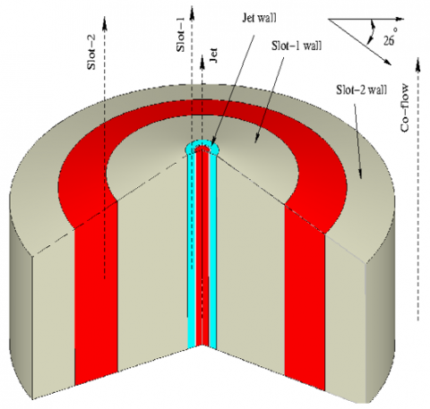
A detailed diagram of multi-regime burner (MRB) is presented in Figure 1 was developed by Butz et al. [11] and Popp et al. [12].
Figure 1. Schematic diagram of the MRB
The MRB works independently with varying equivalence ratios. The burner inlets involve a central jet, surrounded by two annular slots.
Table 1. Details of the burner geometry parameters
|
|
Jet |
Slot-1 |
Slot-2 |
Co-flow |
|
Mixture |
CH4-air |
air |
CH4-air |
air |
|
Velocity (m/s) |
Uj=105 |
Case-B: Us1=15 |
Us2=20 |
Ucf =1 |
|
Temperature (K) |
Tj =309 |
Ts1=1880 |
Ts2=307 |
Tcf =300 |
|
Reynolds number |
Rej =18550 |
Res1=174 |
Res2=23960 |
-- |
|
Equivalence ratio |
ϕj = 1.4, 1.8, 2.2, 2.6. |
ϕs1=0 |
ϕs2=0.8 |
ϕcf=0 |
The central jet and slot-2 inject the fuel-air mixture, while slot-1 injects pure air. Mixing occurs at the exit of slot-1 and slot-2, aided by the slot-1 wall that stabilizes the reaction zone. Additional co- flowing air is supplied with 1 m/s throughout the burner. The burner outlet diameter is 0.04 m. It consists of a central inflow jet with an internal and outer diameter of 0.003 m and 0.0033 m. The jet is encircled by circular slot-1, which has an outer diameter of 0.007 m. Additionally, there is a second hollow slot (slot-2) with an inner and outer diameter of 0.04 m and 0.06 m. In the present work, 26˚ angle is considered for a staged slot burner. The detail operating parameters have been mentioned in Table 1.
2.1 Governing equations
In the present study, the average flow field is axis-symmetric in nature, a wedge shape computational domain has been considered for numerical study. A two-dimensional axis-symmetric, steady-state in-compressible turbulent combustion field is solved using standard κ-ε model [41, 42]. The governing equations for mass, momentum, enthalpy, and concentration of chemical species have been solved using the RANS approach [43] as discussed below.
Mass conservation:
$\frac{\partial}{\partial x_j}\left(\rho u_j\right)=0$ (1)
Momentum conservation:
$\frac{\partial}{\partial x_j}\left(\rho u_i u_j\right)=-\frac{\partial p}{\partial x_i}+\frac{\partial}{\partial x_j}\left[\tau_{i j}-\overline{\rho u_i^{\prime} u_j^{\prime}}\right]+\rho g$ (2)
where, $\tau_{i j}$ is stress tensor:
$\tau_{i j}=\mu\left(\frac{\partial u_i}{\partial x_j}+\frac{\partial u_j}{\partial x_i}\right)$ (3)
Energy conservation:
$\frac{\partial}{\partial x_j}\left(\rho h u_j\right)=\frac{\partial}{\partial x_j}\left[\rho \alpha \frac{\partial h}{\partial x_j}-\overline{\rho h^{\prime} u_j^{\prime}}\right]-\frac{\partial}{\partial x_j}\left(q_r\right)+S_{h c}$ (4)
Chemical species:
$\frac{\partial}{\partial x_j}\left(\rho u_j Y_s\right)=\frac{\partial}{\partial x_j}\left[\left(\rho D_s+\frac{\mu_t}{S c_t}\right) \frac{\partial Y_s}{\partial x_j}\right]+\dot{\omega}_s$ (5)
where, $u_i$, p, and h are average velocity, pressure, and enthalpy, respectively. The ρ and μ are the density and dynamic viscosity of the fluid, respectively. The $\alpha, q_r, S_{h c}$ and $D_s$ represent thermal diffusivity, radiative heat loss, combustion source term and molecular diffusion coefficient of species, respectively. In Eq. (5), $Y_s$ and $\dot{\omega}_s$ refers to the average mass fraction of species and the average species consumption rate, respectively. The subscript “s” represents the species involved in the combustion. In the present study, the turbulent Schmidt number ($S c_t$) is assigned as 0.7. The selection of $S c_t$ number strongly affects the temperature and distribution of species. The term Reynolds stress $\left(-\overline{\rho u_l^{\prime} u_{\jmath}^{\prime}}\right)$ and turbulent heat flux $\left(-\overline{\rho h^{\prime} u_{\jmath}^{\prime}}\right)$ in Eq. (2) and Eq. (4) requires further modeling. The Reynolds stresses $\left(-\overline{\rho u_l^{\prime} u_{\jmath}^{\prime}}\right)$ are approximated using the Boussinesq eddy viscosity assumption [43, 44]:
$-\overline{\rho u_{\imath}^{\prime} u_{\jmath}^{\prime}} \approx \mu_t\left(\frac{\partial u_i}{\partial x_j}+\frac{\partial u_j}{\partial x_i}\right)-\frac{2}{3}\left(\rho \kappa \delta_{i j}\right)$ (6)
where, $\delta_{i j}$ and $\mu_t$ are the Kronecker delta and turbulent viscosity, respectively. The turbulent heat flux $\left(-\overline{\rho h^{\prime} u_{\jmath}^{\prime}}\right)$ is obtained through gradient hypothesis:
$-\overline{\rho h^{\prime} u_{\jmath}^{\prime}} \approx \frac{\mu_t}{P r_t}\left(\frac{\partial h}{\partial x_j}\right)$ (7)
where, $P r_t=0.85$ is the turbulent Prandtl number. The turbulent viscosity ($\mu_t$) is calculated as:
$\mu_t=\left(\frac{\rho c_\mu k^2}{\varepsilon}\right)$ (8)
where, the turbulent kinetic energy (κ) and the turbulent dissipation rate (ε) are estimated using standard $\kappa-\varepsilon$ model [41] as follows:
Transport equation of κ:
$\frac{\partial\left(\rho \kappa u_j\right)}{\partial x_j}=\frac{\partial}{\partial x_j}\left[\left(\mu+\frac{\mu_t}{\sigma_\kappa}\right) \frac{\partial \kappa}{\partial x_j}\right]+G_\kappa-\rho \varepsilon$ (9)
Transport equation of ε:
$\frac{\partial\left(\rho \varepsilon u_j\right)}{\partial x_j}=\frac{\partial}{\partial x_j}\left[\left(\mu+\frac{\mu_t}{\sigma_{\varepsilon}}\right) \frac{\partial \varepsilon}{\partial x_j}\right]+G_\kappa \frac{\varepsilon}{\kappa} C_{\varepsilon 1}-\rho \frac{\varepsilon^2}{\kappa} C_{\varepsilon 2}$ (10)
where, $G_\kappa$ is the rate of turbulence kinetic energy production which is calculated as:
$G_\kappa=-\overline{\rho u_{\imath}^{\prime} u_{\jmath}^{\prime}} \frac{\partial u_j}{\partial x_j}$ (11)
where, $C_{\varepsilon 1}=1.44, C_{\varepsilon 2}=1.92, C_\mu=0.09, \sigma_\kappa=1.0$ and $\sigma_{\varepsilon}=1.3$ are constants of the standard $\kappa-\varepsilon$ model [42, 45].
2.2 Combustion modeling
Fuel combustion relies mainly on how chemical reactions interact with turbulent flow. Turbulence increases the mixing of small particles, which speeds up combustion reactions. Numerous finite-rate chemistry methodologies and combustion modeling techniques have been employed to elucidate chemical kinetics in combustion computations. Gas-phase combustion is primarily described by the reaction mechanism and its corresponding reaction rate. The open FOAM chemistry solver uses CHEMKIN-II data for the integration of complex chemical kinetics in fluid dynamics simulations. The GRI 3.0 gas-phase chemical kinetic model was implemented in the present calculations, including 36 species and 218 reactions. It provides detailed information on the combustion process while balancing computing cost and simulation accuracy. An analysis of the methane-air combustion mechanism takes place using a generalized finite-rate chemistry model Laminar flame simulations and relevant experimental data are used to investigate the mixture fraction. The mixture fraction is a crucial variable in the differentiation of non-homogeneous systems. The mixture fraction (Z) is calculated using Bilger, mixture fraction [46] is defined as:
$Z=\frac{\frac{2\left(Y_C-Y_{C_2}\right)}{W_C}+\frac{Y_H-Y_{H_2}}{2 W_H}-\frac{Y_O-Y_{O_2}}{2 W_O}}{\frac{2\left(Y_{C_1}-Y_{C_2}\right)}{W_C}+\frac{Y_{H_1}-Y_{H_2}}{2 W_H}-\frac{Y_{O_1}-Y_{O_2}}{2 W_O}}$ (12)
where, Y and W are elemental mass fractions and atomic weights of (H), carbon (C), and oxygen (O) respectively. This process allows for the calculation of accurate measurements in the field of chemistry. The subscript 1 refers to the fuel stream, and 2 relates to the air stream. The progress variable quantifies the advancement of a specific location in the combustion zone during the reaction, leading to faster simulations while accurately predicting combustion behavior. The progress variable ($Y_C$) is defined as the sum of CO2 and H2O mass fractions is being discussed in previous studies [29].
$Y_C=Y_{H_2 \mathrm{O}}+Y_{C O_2}$ (13)
2.3 Eddy dissipation concept
The interaction between combustion and turbulence is critical in turbulent combustion. The Eddy Dissipation Concept is used to calculate combustion rates using microscopic values to determine the effects of chemical kinetics reaction and mixing for the reacting turbulent flow modelling [47]. Chemical reactions transpire when the reactants are blended at a molecular level, with the turbulence energy dissipation occurring within the micro structural size of the Kolmogorov scales. The severely strained zone only contributes a small portion of the flow in a turbulent flow. These areas make it easier for turbulence to turn into heat and for reactants to mix on a molecular level [48]. The eddy-dissipation model is a widely recognized approach that accurately determines the rate at which reactants are mixed by turbulent fluctuation, based on the underlying principles of chemical kinetics. This model is particularly useful in modeling combustion problems, whether they are premixed or non-premixed. In the present study, radiation is modeled using the P1-approximation [49].
2.4 Computational domain and boundary conditions
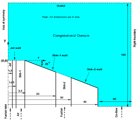
In the present study, the nature of the averaged flow field is axis-symmetric [11, 12]; which allows consideration of a wedge two-dimensional, axis-symmetric computational domain for numerical simulations as shown in Figure 2. Where, the various dimensions of the computational domain are shown in mm. The origin (r=0, y=0) of the computational domain is placed on the axis of symmetry, at the exit of the central jet. The computational domain consists of the premixed outer reaction zone, recirculation zone, and lifted inner reaction zone. In order to lower the computational cost, only half of the burner was chosen as the computational region. The burner is placed at a sufficient distance away from the right boundary and outlet, as depicted in Figure 2. In order to reduce the numerical error associated with boundary conditions. The computational domain’s right and outlet boundaries are exposed to the atmosphere, maintaining a gauge pressure of zero. Zero-gradient boundary conditions are applied to temperature, velocity, and species concentrations. The domain features four in- lets: jet, slot-1, slot-2, and co-flow, where specific fuel-air mixtures are introduced through the jet and slot-2 at predefined velocities. The pressure over the wall and inlet of domain are treated with zero gradient boundary condition. The boundary conditions are discussed in Table 2.
Figure 2. Schematic diagram of the MRB computational domain
Table 2. Details of the boundary conditions
|
Jet inlet |
ϕj =1.4, 1.8, 2.2, 2.6. Tj=309 K, Uj=105 m/s, Rej=18550, Lt=1.5×10⁻³. |
|
Slot-1 inlet |
ϕs1 =0, Ts1=1800 K, Res1=174, Lt=1.85×10⁻³, Us1=15 m/s for Case-B. |
|
Slot-2 inlet |
ϕs2 =0.8, Ts2=307 K, Res2=23960, Lt=0.01, Us2=20 m/s. |
|
Co-flow inlet |
ϕcf =0, Tcf =300, Ucf = 1 m/s, Lt=0.14. |
|
Outlet and right side boundary |
$\frac{\partial \xi}{\partial x}=0$, where ξ= Uj, Us1, Us2, Ucf, κ, ε, ϕ; $\frac{\partial T}{\partial x}=0$. |
The values of turbulent kinetic energies (κ) and dissipation rates of turbulent kinetic energy (ε) for jet, slot-1, slot-2, and co-flow are estimated using the following relations [41]:
$\kappa=1.5\left(U I_t\right)^2$ (14)
$\varepsilon=\frac{C_\mu^{0.75} \kappa^{1.5}}{L_t}$ (15)
where, $c_\mu=0.09$, It and Lt are turbulent intensity and turbulent characteristic length scale, for the all the inlets, 5% turbulent intensity (It) is considered.
2.5 Numerical schemes
In this study, the governing equations of a two-dimensional multi-regime combustion burner are solved numerically using CFD package Open FOAM [50]. Open FOAM provides data availability in advance to find the Reacting Foam solver for combustion with chemical reactions. Reacting Foam has a benchmark solver with analytical solutions and also solves the fully compressible Navier-Stokes equations to capture the turbulent structure of the flow. The governing equations are discretized using a combination of second-order central difference scheme for convective terms and second-order upwind difference scheme for advective terms. The transient term is discretized using a local-Euler scheme with first-order implicit local time step to enhance stability of the steady-state solution. The PIMPLE algorithm is a combination of SIMPLE [51] and PISO [52] algorithms, the PIMPLE algorithm with three corrector loops used for pressure velocity coupling and applies one inner and two outer correctors loops used in present simulation. In the present study, numerical schemes used available in Open Foam are discussed in detail. The pressure correction equation was resolved using the pre-conditional conjugate gradient (PCG) symmetric solver, employing a convergence criterion of 10-7 in each time step. An absolute tolerance error of 10-6 was set for each time step. Other equations solved using preconditioned bi-conjugate gradient (PBiCG) asymmetric solver. Courant number is maintained less than 0.5 throughout the simulation. In this numerical study, the approximate average time step 10-4 seconds has been considered.
The grid’s structure and density affect the accuracy of the computational results. The flow field of the current MRB is symmetric in nature. This allows us to use a two-dimensional wedge shape for our numerical studies Figure 3(a). Refining the mesh around the burner exit and wall has been considered to accurately assess boundary layer effects and the re-circulation zone as shown in Figure 3(b). The uniform structured grid is considered in the other part of the computational domain, as shown in Figure 3(b). The hexahedral grid enhances computational speed and encompasses nearly all regions of the computational domain, except for areas where mesh density transitions occur.
(a) Top view of wedge domain
(b) The zoomed view grid distribution
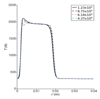
(c) Profile of mixture fraction
(d) Profile of temperature
Figure 3. Grid distribution and grid independence test for MRB computational domain
A grid-independent test has been conducted for Case-B at φj = 2.6. The profiles of mixture fraction and temperature has been presented at an axial distance of y=0.09 m for four different grid sizes shown in Figure 3(c) and Figure 3(d). As grid density increases, it is observed that the temperature profile remains unchanged for grid resolutions of 1.23×10⁵ and 8.75×10⁵, indicating that the results are grid-independent. For this analysis, the higher grid density of 1.23×10⁵ was selected to ensure computational accuracy. The chosen mesh consists of 1.23×10⁵ grid points, resulting in 6.01×10⁴ cells comprised of 5.95×10⁴ hexahedral cells and 411 prism-type cells. Notably, hexahedral cells account for 99% of the grid distribution, which significantly reduces the computational time for each iteration. The mesh exhibits a maximum skewness of 0.53 and an average non-orthogonality of 1.52.
This section presents numerical results from the RANS-EDC model for methane-air combustion in multi-regime combustion. The influence of burner inclination angle (θ) and equivalence ratio (φj) on the flow field in multi-regime combustion is discussed herein. Butz et al. [11] conducted an experimental study using Raman/Rayleigh/CO-LIF scattering techniques to assess the mixture fraction, temperature, and mass fraction of species present. They pro- vided experimental data corresponding to a burner inclination angle of 26˚ and φj=2.6 for Case-B, with a slot-1 velocity of 15 m/s. These experimental data were used to compare with the present numerical results.
4.1 Mean flow field of velocity and progress variable
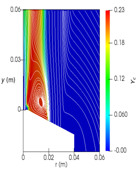
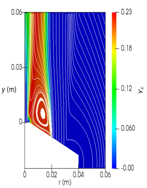
Streamlines are plotted on the velocity magnitude contours to illustrate the flow field of the MRB, as shown in Figure 4(a). Figure 4(a) shows, the high-velocity stream coming out from the jet and slot-1 generates a shear layer that augments fluid inflow. The stream from slot-2 and co-flow are drawn towards the axis of MRB at y=0.75 m, resulting in the formation of a neck- shaped structure. Furthermore, streams tend to move away from the neck area and expand in the outer radial direction. The slot-1 wall acts as a bluff body, creating a re-circulation zone with lower velocity magnitude. The flow becomes trapped within the recirculation region, thereby improving the mixing characteristics of the flow and subsequently stabilizing the MRB flame. The streamlines are superimposed on the progress variable ($Y_C$) contour to analyze the overall flow field of the MRB, as illustrated in Figure 4(b). The $Y_C$ shows how the combustion process changes from the unburnt reactants to the burnt products.
The progress variable is defined as the sum of mass fraction of the CO2 and H2O, and is calculated from Eq. (13). The presence of the $Y_C$ indicates that the chemical reaction has already commenced, with Z being within the flammability range in those specific areas. Moreover, the higher $Y_C$ value signifies that the chemical reaction is more vigorously active in comparison to areas where lower values of the progress variable were detected. In accordance with this concept, the flow region near to the MRB is separated into four distinct sub-regions. As illustrated in Figure 4(b), a detailed depiction of the recirculation zone reveals the presence of the lifted inner reaction zone (LIRZ), recirculation zone, premixed inner reaction zone (PIRZ), and premixed outer reaction zone (PORZ), exhibiting streamline overlays on the progress variable contour. It is noted that the flame is attached to the edge of the bluff body due to adequate mixing and stabilization in the recirculation region. The jet releases a highly reactive mixture surrounded by low-velocity air from slot-1. A small layer of mixing is established between the reactants from slot-2 and the co-flowing air, and this shear layer between the jet and slot-1 enhances mixing, as shown in Figure 4(b).
(a) Streamline on the mean velocity contour (Umag)
(b) Streamline on the contours of the progress variable (Yc)
Figure 4. Streamline plots overlaid on the mean flow field contours of the MRB
(a) At θ=22˚
(b) At θ=26˚
(c) At θ=30˚
Figure 5. Comparison of streamlines on the contours of progress variable (Yc) at different burner inclination angle (θ)
Figure 5 illustrates the radial profiles of the progress variable, highlighting significant difference among various burner inclination angles (θ = 22˚, 26˚, 30˚) specifically at the lowest axial position (y=0.006 m). At this position, the width of the reaction zone is broader due to the increased exit velocity from slot-1. Increasing the inclination angle of the burner causes the flame’s neck to shift along the axial location. Additionally, the premixed outer reaction zone gradually shifts inward as the recirculation zone width decreases.
4.2 Numerical validation
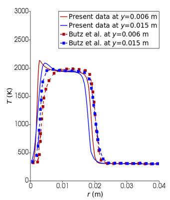
The radial profiles of mixture fraction (Z) at various axial positions (y=0.006 m to y=0.03 m) have been compared with the experimental data obtained by Butz et al. [11] as shown in Figure 6 for Case-B at ϕj=2.6. The effect of burner inclination angle and equivalence ratio near to burner exit has been studied. The mixture fraction (Z) represents the normalized parameter of the fuel-air mixture and is calculated using Eq. (11), which was developed by Bilger et al. [46]. A rich fuel mixture is ejected from the jet and is responsible for the noticeable increase in mixture fraction along the MRB’s central axis. The values of the mixture fraction gradually diminish within the premixed inner reaction zone and subsequently stabilize within the re-circulation zone. In the present numerical result, it is found that the lifted inner reaction zone forms adjacent to the burner in comparison with experimental results. This leads to deviations between the experimental and numerical values of the mixture fraction at y=0.006 m as shown in Figure 6(a) and Figure 6(b). Additionally, the mixture fraction decreases on going outward in the premixed outer reaction zone." The experimental results indicate that the mixture fraction has the same value (Z=0.048) in both the recirculation zone and the slot-2 stream. However, in the numerical results, a lower mixture fraction is observed in the recirculation zone (Z=0.04) compared to the slot-2 stream (Z=0.043). This is attributed to a developed reaction in the recirculation zone, leading to a reduction in the mixture fraction value. Moving towards the co-flow region, the mixture fraction continues to decrease. A close match in the profile pattern is observed, despite the numerical results predicting a lower value. Comparing with experimental data, it is confirmed that the detailed mechanisms describing turbulence-chemistry interactions yield reasonable results. The temperature distribution across radial positions at various axial locations (y=0.006 m to 0.03 m) has been meticulously examined in connection with empirical data, depicted in Figure 7. Near the burner exit, the temperature profiles exhibit resemblances to those observed in the experimental data, albeit with minor discrepancies in the magnitude of the values as illustrated in the Figure 7(a) and Figure 7(b). It is observed that the numerical results show a slight overestimation of temperature values in close proximity to the axis of the burner. However, a high level of accuracy is achieved when comparing high and low-temperature values. Additionally, it is evident that there exists a peak temperature value (2148 K) near the burner’s axis in the stream of slot-1. This phenomenon can be attributed to the formation of a "Lifted inner reaction zone" occurring much closer to the burner exit than indicated by the experimental results.
(a)
(b)
Figure 6. Comparison of mixture fraction profile with the experimental results of Butz et al. [11] for Case-B at ϕj=2.6
The temperature values and profiles also closely match in the re-circulation region. However, in the numerical results, the re-circulation zone is found to be inclined towards the burner axis and is relatively smaller in height compared to the experimental results. The temperature values in the premixed outer reaction zone decrease more quickly than the experimental data illustrated in Figures 7(a) and 7(b).
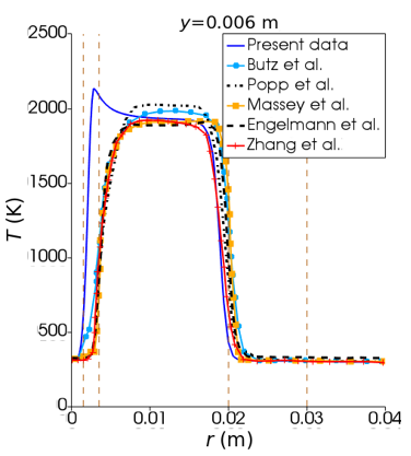
Figure 8 presents a comparison of the mixture fraction (Z), temperature (T) and mass fraction of carbon monoxide ($Y_{C O}$) for Case-B at φj=2.6. These results are plotted in the radial direction at an axial location of y=0.006 m. The numerical results show a strong alignment with the experimental findings of Butz et al. [11], and the numerical results from Popp et al. [12], Massey et al. [13], Engelmann et al. [14], Zhang et al. [15] for Case-B at φj=2.6. Near the central axis of the burner (0.003 m < r < 0.008 m), the Z values in the inner premixed reaction zone closely match the numerical, experimental, and Large Eddy Simulation (LES) results (Figure 8(a)). Closer to the burner exit in the slot-1 stream, a lifted inner reaction zone is observed. This occurs due to the mixing of air from slot-1 with the hot products from the outer reaction zone, resulting in variations in the Z value. In the recirculation zone, the mixture fraction values reported by Engelmann et al. [14] and Zhang et al. [15] are slightly lower than the experimental results from Butz et al. [11]. Additionally, the LES profiles are slightly shifted outward. As we move radially outward, the Z values gradually decrease and remain constant within the recirculation zone.
(a)
(b)
Figure 7. Comparison of temperature profile with the experimental results of Butz et al. [1] for Case-B at ϕj=2.6
(a) Profiles of mixture fraction
(b) Profiles of temperature
(c) Profiles of carbon monoxide
Figure 8. Comparison of mixture fraction, temperature and mass fraction of carbon monoxide (Case-B, φj=2.6) with the results of Butz et al. [11] (experimental); and with the numerical results of Pope et al. [12], Massey et al. [13], Engelman et al. [14] and Zhang et al. [15]
Figure 8(b) illustrates that the current numerical results tend to slightly overestimate the temperature values near the burner axis. Nonetheless, a strong correlation has been established in terms of both high and low temperature values. It has been observed that the peak temperature near the burner axis arises from the formation of a "lifted inner reaction zone," which occurs closer to the burner exit compared to the findings from experimental data. Furthermore, the temperature profiles and their corresponding values within the recirculation zone demonstrate a high level of agreement. However, the numerical results suggest that the recirculation zone is inclined towards the burner’s axis and exhibits a shorter height when contrasted with the experimental results. Consequently, the temperature values within the "premixed outer reaction zone" exhibit a more rapid decline than those reported in the experimental measurements.
It has been observed that at y=0.006 m in the premixed inner reaction zone, there is a significant increase and decrease in the values of $Y_{C O}$ compared to other numerical results, as shown in Figure 8(c). This behavior has not been noted by other studies [11-15]. The RANS-EDC approach struggles to accurately predict $Y_{C O}$ levels in the premixed inner reaction zone, where high shear flow occurs. The peak value of $Y_{C O}$ in this zone has been attributed to incomplete combustion of the mixture. Near the burner exit at y=0.006 m, the RANS-EDC model overpredicted the mass fractions of $Y_{C O}$ in the premixed inner reaction zone when compared to experimental results [11]. However, improved predictions of $Y_{C O}$ have been observed on the outer side of the premixed inner reaction zone. In the recirculation zone, complete combustion of methane results in almost zero $Y_{C O}$ values near the burner exit (0.005 m ≤ r ≤ 0.017 m). Moving further into the far-field, an increase in the presence of $Y_{C O}$ on the outer side of the premixed inner reaction zone has been well predicted, as illustrated in Figure 8c.
A secondary peak of carbon monoxide $Y_{C O}$ has been identified in slot-2. The LES-ATF results indicate a slight overestimation of slight overestimation of $Y_{C O}$ at y=0.006 m and y=0.015 m in the outer premixed reaction zone [12]. The mixing of the rich jet mixture with oxidizer from slot-1 is not accurately captured due to LES limitations with very lean mix- tures. Using tabulated chemistry, $Y_{C O}$ formation is overestimated in this zone. Massey et al. [13] used a two-progress variable approach to accurately predict $Y_{C O}$ in the outer premixed reaction zone, while a one-progress variable approach leads to over-prediction in burned regions. The DTF model similarly overestimates $Y_{C O}$ due to flame thickening and wrinkling losses, affecting minor species predictions; Zhang et al. [15] proposed improvements for this model to predict the minor species. Near the jet axis, $Y_{C O}$ values have slight overestimations compared to Butz et al. [11], while $Y_{C O}$ values from Massey et al. [13] and Zhang et al. [15] are underpredicted. Overall, the current study struggles to accurately predict $Y_{C O}$ mass fraction in the outer premixed reaction zone, even as co-flow region $Y_{C O}$ values approach zero.
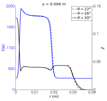
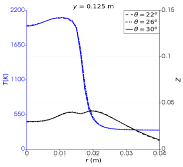
Figure 9 shows the temperature and mixture fraction profiles for different burner inclination angles at various axial locations: y=0.006, 0.015, 0.03, 0.06, 0.125 and 0.15 m. The temperature gradually increases at the burner’s location between 0.006 and 0.03 m, reaching a high value of 2148 K before the inner premixed reaction zone. The mixture fraction consistently decreases toward the outer layer of the inner premixed zone. The re-circulation zone maintains a nearly constant mixture fraction around 0.04. A slightly higher mixture fraction of 0.047 is observed in slot-2, indicating the absence of a chemical reaction. In the co-flow region, the mixture fraction decreases rapidly, identifying the non-reactive region in the flow field. After the flame’s neck (y≳0.075), the mixture fraction ranges from Z=0.03 to 0.05, indicating the convergence and divergence of the flame towards and from the burner’s axis. The mixture fraction value near the axis of the burner decreases and reaches a constant value (Z≲0.041) in the far field (0.125≲y≲0.15 m) due to complete combustion of the methane-air mixture. The burner inclination angle does not affect the far field. Meanwhile, the temperature increases near the center of the jet axis and reaches a constant temperature value in the far field (0.125≲y≲0.15 m) as shown in Figure 9(e) and Figure 9(f).
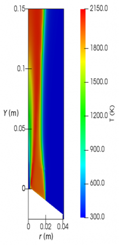
Figure 10 compares temperature contours at three burner inclination angles. In the re-circulation zone, no fuel remains after combustion. The red color indicates a high product formation rate with high chemical reaction production rates. The temperature remains constant at the axial location (0.125≲y≲0.15 m). Slightly lower temperature values are observed in the outer premixed reaction zone for a higher burner inclination angle (θ=30˚) at the axial location (0.006≲y≲0.03 m). At y=0.06 m, a lower burner inclination (θ=22˚) shows the presence of wider re-circulation compared to θ=30˚.
(a)
(b)
(c)
(d)
(e)
(f)
Figure 9. Comparison of temperature profile with different burner inclination angle (θ=22˚, 26˚, 30˚) for Case-B at ϕj=2.6
In Figure 11, the impact of burner inclination on the mass fractions of methane ($Y_{\mathrm{CH}_4}$), carbon monoxide ($Y_{\mathrm{CO}}$), and progress variable ($Y_C$) is depicted. Near the jet, there is a high concentration of methane, which decreases as we move towards the inner side of the premixed inner reaction zone. Complete combustion of methane takes place in the recirculation zone, resulting in a lower methane mass fraction as shown in Figure 11(a). The inner reaction zone remains unaffected by changes in the burner inclination angle (θ=22˚, 26˚, 30˚), but slight differences are observed in the recirculation zone.
(a) At θ=22˚
(b) At θ=26˚
(c) At θ=30˚
Figure 10. Comparison of temperature contours at different burner inclination angle (θ)
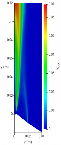
(a) At ϕj =2.6
(b) At ϕj =2.6
(c) At ϕj =2.6
Figure 11. Contours of mass fractions of methane $\left(Y_{\mathrm{CH}_4}\right)$, carbon monoxide $\left(Y_{\mathrm{CO}}\right)$, and progress variable $\left(Y_C\right)$
In the recirculation zone, complete combustion of methane occurs, leading to lower methane mass fractions. Additionally, the red color in the figures indicates high product formation and chemical reaction production rates, along with maximum temperature in the recirculation zone.
Higher mass fractions of carbon monoxide are visible in the inner and outer premixed reaction zones, as well as in the far field, as seen in Figure 11(b). The formation of ($Y_{\mathrm{CO}}$) is thicker in the inner premixed reaction zone and thinner in the outer premixed reaction zone. Near the jet exit and in the recirculation zone, there are almost zero carbon monoxide values. In the co-flow region, no carbon monoxide values are observed. The contour plot of the progress variable is shown in Figure 11(c). The $Y_C$ value progressively rise in the inner premixed reaction zone, reaching its highest point in the recirculation zone. Subsequently, the $Y_C$ values sharply decrease in the outer premixed reaction zone and reach zero in the slot-2 stream.
(a)
(b)
(c)
(d)
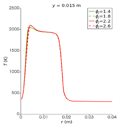
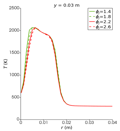
Figure 12. Comparison of profiles of temperature at different equivalence ratio (φj)
(a)
(b)
(c)
(d)
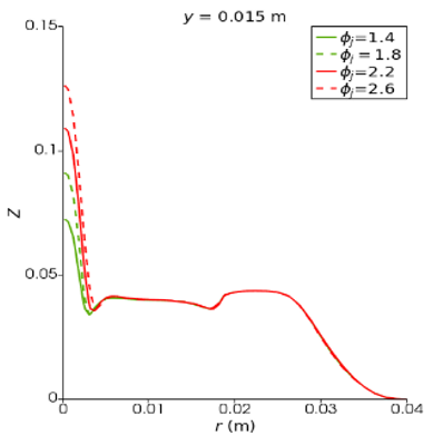
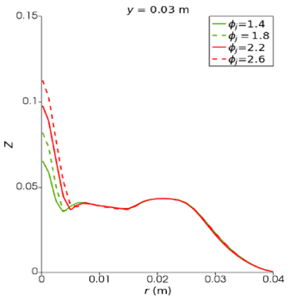
Figure 13. Comparison of profiles of mixture fraction at different equivalence ratio (φj)
Figures 12 and 13 presents the radial profiles of temperature and mixture fraction for Case-B at four distinct jet equivalence ratios (φj=1.4, 1.8, 2.2, 2.6). The analysis shows that temperature values progressively rise along the axial location of the burner, reaching a maximum just before transitioning into the inner reaction zone. Following this peak, the temperature remains relatively constant throughout the axial direction. It is observed that, within the inner premixed reaction zone, lower temperature readings occur at higher jet equivalence ratios. This trend suggests that an increase in the equivalence ratio results in a more extended inner premixed reaction zone along the axial path. Importantly, the jet equivalence ratio does not appear to influence the far field. In the outer premixed region, temperature values tend to increase with higher jet equivalence ratios, particularly in areas situated farther from the burner. Furthermore, the combination of lower temperatures in the inner premixed zone and higher inner premixed equivalence ratios is associated with a lengthened inner premixed re- action zone. As the jet equivalence ratio increases, elevated temperature values in the outer premixed zone become apparent. Finally, it is noted that the variation of the mixture fraction is predominantly significant near the axis of the burner, exhibiting a continuous decrease from higher to lower values within the co-flow region, ultimately reaching zero in the more distant areas of the co-flow.
(a)
(b)
(c)
(d)
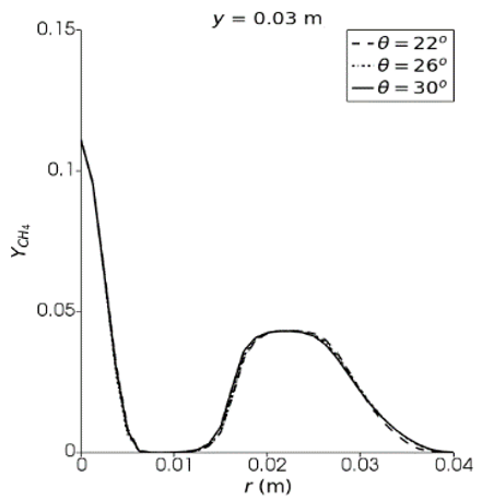
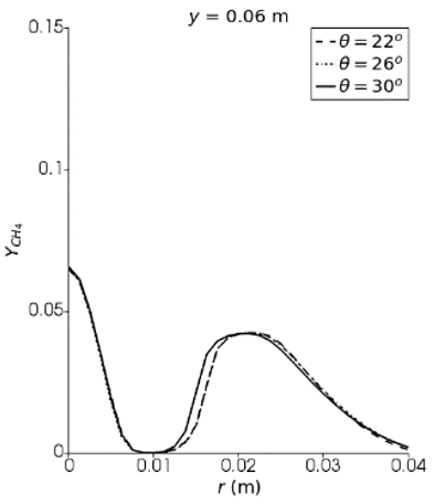
Figure 14. Comparison of profiles of mass fractions of methane at different equivalence ratio (φj)
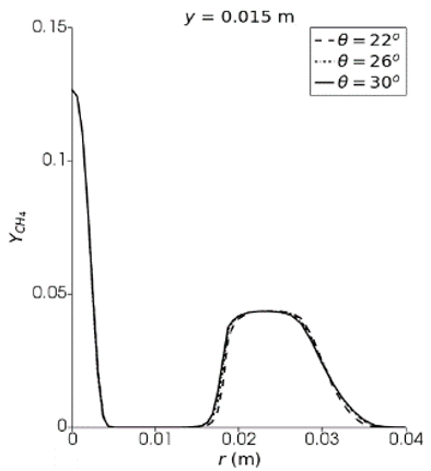
4.3 Profiles of methane mass fraction
Figure 14 illustrates the comparison of the mass fraction of methane ($\mathrm{Y}_{\mathrm{CH}_4}$) profiles at various burner inclination angles (θ=22˚, 26˚, 30˚), along different axial positions for Case-B at φj=2.6. The highest concentrations of $\mathrm{Y}_{\mathrm{CH}_4}$ are observed at the jet exit, while zero values are found in the co-flow region. Near the burner exit at y=0.006 m, the maximum $\mathrm{Y}_{\mathrm{CH}_4}$ values occur close to the jet exit but gradually decrease as one moves radially through the inner pre- mixed reaction zone. This reduction in $\mathrm{Y}_{\mathrm{CH}_4}$ concentration is attributed to the chemical reactions that commence in this inner premixed zone. As the flow enters the recirculation zone, the $\mathrm{Y}_{\mathrm{CH}_4}$ concentration approaches zero, indicating that complete combustion of methane occurs in this area (Figure 14(a)-Figure 14(d)). Upon entering the outer premixed zone, $\mathrm{Y}_{\mathrm{CH}_4}$ concentrations increase rapidly but then decrease progressively in the outer shear layer of the slot-2 stream, ultimately reaching zero in the co-flow region. The $\mathrm{Y}_{\mathrm{CH}_4}$ profile close to the jet exit shows no chemical reactions taking place (from y=0.006 m to 0.03 m), with a mass fraction of methane observed at around 0.128 at φj=2.6. Increasing the burner inclination angle does not significantly change the methane values up to the axial position of y=0.03 m. However, in the far field at y=0.06 m, a slight deviation is noted in the outer premixed reaction zone. Moving towards the far region, it is found that the profiles of $\mathrm{Y}_{\mathrm{CH}_4}$ which shows the spread of flame in the radial direction. The mass fraction of methane is present only in the slot-2 stream, with the $\mathrm{Y}_{\mathrm{CH}_4}$ values gradually decreasing toward the co-flow region. Mixing of reactants and products of slot-2 by the pure air of co-flow can be another reason for the deviation of the outer reaction zone to the outside from the inner reaction zone.
(a)
(b)
(c)
(d)
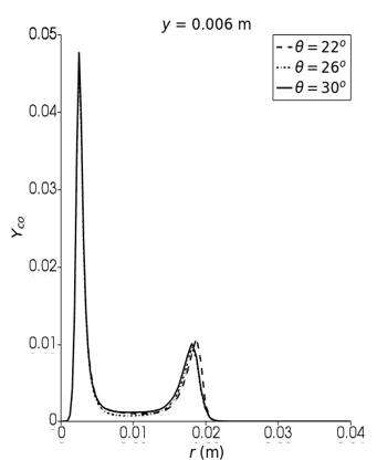
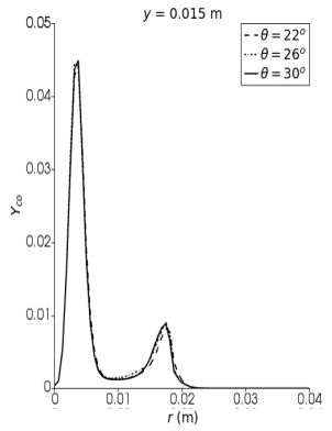
Figure 15. Comparison of mass fraction of carbon monoxide profile for different burner inclination angle (θ) at different axial position for Case-B at ϕj=2.6
4.4 Profiles of carbon monoxide
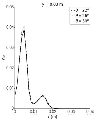
Figure 15 illustrates the mass fraction of carbon monoxide ($\mathrm{Y}_{\mathrm{CO}}$) at different burner inclination angles (θ). The formation of $Y_{\mathrm{CO}}$ plays a significant role in multi-regime combustion. The profiles show sharp increases and decreases in $Y_{\mathrm{CO}}$ within the inner premixed reaction zone. This behavior has been accurately predicted by the RANS-EDC model. In the inner premixed reaction zone, a higher $Y_{\mathrm{CO}}$ value (≈ 0.0481) was observed, indicating incomplete combustion of the methane-air mixture (as shown in Figure 15(a)). The highest peak has been observed in the axial location from y = 0.006 to 0.03 m. Carbon monoxide strongly absorbs infrared radiation, significantly impacting thermal radiation during combustion. The P1-approximation model does not account for this, resulting in limitations in predicting radiative heat transfer. More advanced models like OTM and SNB can provide more accurate results [53]. However, due to its computational efficiency, the simplified radiative transfer model P1-approximation has been used in the present study, despite its limitations in predicting radiative heat transfer. As the mixture enters the recirculation zone, the value of carbon monoxide rapidly decreases, indicating complete combustion of the methane-air mixture in the recirculation zone. Moving further into the far field, $Y_{\mathrm{CO}}$ gradually decreases, indicating better reaction compared to the inner reaction zone. In the outer premixed reaction zone, a slightly higher value (0.012) of $Y_{\mathrm{CO}}$ has been observed, indicating incomplete combustion of the methane-air mixture. In slot-2 of the stream, the $Y_{\mathrm{CO}}$ value becomes zero, indicating no combustion taking place. At different burner inclination angles, there is a difference in the observed $Y_{\mathrm{CO}}$ value in the premixed inner reaction zone as shown in Figure 15(a) and Figure 15(b). This is due to the burner inclination starting from slot-1 wall. A lower burner inclination angle (θ=22˚) shows a slightly increased $Y_{\mathrm{CO}}$ value in the stream of slot-2 (Figure 15(a)), which is in the premixed outer reaction zone. At the axial location y=0.015 m, in the recirculation zone and premixed outer reaction zone, a slight difference in YCO value is observed at θ=22˚ and θ=30˚. A higher peak value has been observed at an axial location of y=0.03 m in the inner premixed reaction for θ=26˚ in comparison with the other angle. Further moving into the far field, not much difference is observed with a change in burner inclination angle.
(a)
(b)
(c)
(d)
Figure 16. Comparison of progress variable at different equivalence ratio (φj)
4.5 Profiles of progress variable
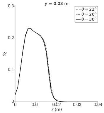
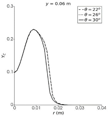
The progress variable ($Y_C$) has been calculated based on Eq. (13). The $Y_C$ represents the sum of the mass fractions of hydrogen dioxide and carbon dioxide. It is assumed that a higher value of $Y_C$ indicates a greater tendency for the chemical reaction to be completed. In the present analysis, the burner inclination angle (θ) has been varied at 22°, 26°, and 30°. The variation of $Y_C$ in the radial direction at different locations of y is presented in Figure 16. In the region close to the burner exit (y=0.006 to y=0.015 m), on entering the inner premixed reaction zone from the direction of the burner axis, the values of $Y_C$ gradually increase from zero to a peak value of ≈ 0.0236. This indicates that moving from the burner axis toward the recirculation zone enhances the tendency for complete reactions, ultimately leading to higher production rates of CO2 and H2O. On moving in the radial direction and passing through the outer premixed reaction zone, a sharp decrease in the values of $Y_C$ with the lean mixture of z is observed and it reaches zero value in the slot-2 stream. This indicates that an incomplete reaction is taking place in the outer premixed reaction zone while there is no reaction in the slot-2 stream. The value of z eventually becomes zero in the co-flow region, there is no reaction due to which the value of $Y_C$ remains zero. Here it is observed that the formation of $Y_C$ is comparatively more in the range of lean mixture. It is also observed here that the value of $Y_C$ increases continuously in the far region (y=0.06 m) on the axis of the burner and reaches maximum value of h 0.23 near the jet central axis. As the burner inclination angle increases, the width of the inner recirculation zone slightly decreases in the outer premixed reaction zone, and subsequently, in the co-flow region, $Y_C$ again reaches zero.
The influence of burner inclination angle is pivotal in enhancing flame stability, optimizing the recirculation zone, and minimizing pollutant emissions. The specific inclination angle significantly impacts the interactions among various combustion zones. A comprehensive analysis of the equivalence ratio provides valuable insights for achieving optimal fuel-air mixtures across diverse operational regimes, thereby enabling precise control over flame stability. The study investigates the behavior of premixed and non-premixed methane-air combustion in a multi-reactor burner (MRB) at different burner inclination angles. The turbulent reactive flow field has been simulated using the standard κ-ϵ turbulence model, while combustion has been modeled with the EDC combustion model. The burner flame was examined at various angles (θ=22˚, 26˚, 30˚) with a slot-1 velocity of 15 m/s (Case-B). Grid-independent results have been obtained, and the numerical results of mixture fraction, temperature, mass fraction of carbon profiles closely match with the experimental [11] and numerical results [12-15]. The study presents the qualitative and quantitative analysis of the mixture fraction (Z), temperature (T), mass fraction of methane ($\mathrm{Y}_{\mathrm{CH}_4}$), mass fraction of carbon monoxide ($Y_{C O}$) and progress variable ($Y_C$). The analysis focuses on how the burner inclination angle affects the far field, recirculation zone, premixed inner reaction zone, and premixed outer reaction zone. The comparison of the mixture fraction profile reveals a gradual decrease in the z value within the premixed inner reaction zone due to the complete combustion of the methane-air mixture. This decrease corresponds to an increase in the temperature in the same region. The formation of a higher mass fraction of carbon monoxide has been identified in the premixed inner reaction zone. Carbon monoxide exhibits a strong absorption of infrared radiation, which significantly influences the heat transfer during combustion processes. The P1-approximation model has limitations in accurately forecasting radiative heat transfer phenomena. Furthermore, a decrease in inclination angles results in elevated CO mass fractions within the outer reaction zone. In the inner reaction zone, a minor variation in $Y_{C O}$ concentrations is observed at y=0.015 m and y=0.03 m. The inner reaction zone remains unaffected by changes in the burner inclination angle (θ=22˚, 26˚, 30˚), but slight differences are observed in the recirculation zone. At y = 0.006 ≤ 0.03, θ=30˚ leads to slightly lower temperatures in the outer reaction zone. At y=0.06, θ=22˚ shows wider re- circulation compared to 30˚. Future research has a broader scope on how burner inclination and equivalence ratio behave in real-world situations, including changing load demands and fuel types. Studies should focus on incorporating advanced diagnostic tools and machine learning could enhance real-time optimization of multi-regime burners.
|
Greek symbols |
|
|
α |
thermal diffusivity |
|
δ |
Kronecker delta |
|
ε |
turbulent dissipation rate |
|
κ |
turbulent kinetic energy |
|
μ |
dynamic viscosity |
|
$\dot{\omega}_s$ |
average species consumption rate |
|
$\phi_{\mathrm{cf}}$ |
equivalence ratio at co-flow |
|
$\phi_{\mathrm{j}}$ |
equivalence ratio at jet |
|
$\phi_{\mathrm{s} 1}$ |
equivalence ratio at slot-1 |
|
$\phi_{\mathrm{s} 2}$ |
equivalence ratio at slot-2 |
|
ρ |
density |
|
$\sigma_{\varepsilon}$ |
standard κ-ε turbulence model constant |
|
$\sigma_\kappa$ |
standard κ-ε turbulence model constant |
|
$\tau$ |
stress tensor |
|
θ |
burner inclination angle |
|
Roman symbols |
|
|
CD1,CD2 |
Constants of cascade model used in eddy dissipation of turbulence energy |
|
Pr |
Prandtl number |
|
$q_r$ |
radiative heat loss |
|
Sc |
Schmidt number |
|
Shc |
Source term |
|
t |
time |
|
$x_i$ |
co-ordinates x, y for i=1,2 respectively |
|
$U_{c f}$ |
air co-flow velocity |
|
$U_{\mathrm{j}}$ |
jet exit velocity |
|
$U_{\mathrm{s} 2}$ |
slot-2 exit velocity |
|
W |
atomic weight |
|
Y |
mass fraction |
|
y |
axial distance |
|
$Y_c$ |
progress variable |
|
$Y_s$ |
mass fraction of species |
|
Z |
mixture fraction |
|
Subscripts |
|
|
i,j |
Cartesian component |
|
t |
turbulent |
|
s |
Species |
|
Superscript |
|
|
ʹ |
fluctuation |
|
˗ |
Reynolds average |
[1] Bohm, B., Frank, J.H., Dreizler, A. (2011). Temperature and mixing field measurements in stratified lean premixed turbulent flames. Proceedings of the Combustion Institute, 33(1): 1583-1590. https://doi.org/10.1016/j.proci.2010.06.139
[2] Kariuki, J., Dawson, J.R., Mastorakos, E. (2012). Measurements in turbulent premixed bluff body flames close to blow-off. Combust and Flame, 159(8): 2589-2607. https://doi.org/10.1016/j.combustflame.2012.01.005
[3] Ciardiello, R., Pathania, R.S., Helou, I.E., Mastorakos, E. (2022). Lean blow-off investigation in a linear multi-burner combustor operated in premixed and non-premixed modes. Applications in Energy and Combustion Science, 9: 100041. https://doi.org/10.1016/j.jaecs.2021.100041
[4] Barlow, R.S., Wang, G.H., Anselmo-Filho, P., Sweeney, M.S., Hochgreb, S. (2009). Application of Raman/Rayleigh/LIF diagnostics in turbulent stratified flames. Proceedings of the Combustion Institute, 32(1): 945-953. https://doi.org/10.1016/j.proci.2008.06.070
[5] Mardani, A., Nazari, A. (2022). Dynamic adjustment of the Eddy Dissipation Concept model for turbulent/combustion interactions in mixed combustion regimes. Combust and Flame, 241: 111873. https://doi.org/10.1016/j.combustflame.2021.111873
[6] Boushaki, T., Zaidaoui, H., Chakchak, S., Ghabi, A., El-Rahman, A.I.A., Ghoniem, A.F. (2023). Impact of oxygen enrichment and CO2-H2O dilution on stability and pollutant emissions of non-premixed swirling turbulent flames. Flow, Turbul Combust, 112: 673-688. https://doi.org/10.1007/s10494-023-00454-x
[7] Wang, Y., Li X.Y., Wang, T., Wan, J. (2024). Lean premixed combustion of methane-air in a novel preheated miniature combustor with a flame holder and porous medium. Chemical Engineering Science, 284: 119475. https://doi.org/10.1016/j.ces.2023.119475
[8] Barlow, R.S., Dunn, M.J., Sweeney, M.S., Hochgreb, S. (2012). Effects of preferential transport in turbulent bluff-body-stabilized lean premixed CH4/air flames. Combust and Flame, 159(8): 2563-2575. https://doi.org/10.1016/j.combustflame.2011.11.013
[9] Tong, Y., Li, M., Thern, M., Klingmann, J., Weng, W., Chen, S., Li, Z. (2017). Experimental investigation on effects of central air jet on the bluff-body stabilized premixed methane-air flame. Energy Procedia, 107: 23-32. https://doi.org/10.1016/j.egypro.2016.12.125
[10] Peters N. (1989). Length and Time Scales in Turbulent Combustion. Turbulent Reactive Flows, New York, NY., 242-256. https://doi.org/10.1007/978-1-4613-9631-4-15
[11] Butz, D., Hartl, S., Popp, S., Walther, S., Barlow, R.S., Hasse, C., Dreizler, A., Geyer, D. (2019). Local flame structure analysis in turbulent CH4/air flames with multi-regime characteristics. Combust and Flame, 210: 426-438. https://doi.org/10.1016/j.combustflame.2019.08.032
[12] Popp, S., Hartl, S., Butz, D., Geyer, D., Dreizler, A., Vervisch, L., Hasse, C. (2020). Assessing multi-regime combustion in a novel burner configuration with large eddy simulations using tabulated chemistry. Proceedings of the Combustion Institute, 38(2): 2551-2558. https://doi.org/10.1016/j.proci.2020.06.098
[13] Massey, J.C., Li, Z., Chen, Z.X., Tanaka, Y., Swaminathan, N. (2023). Large eddy simulation of multi-regime combustion with a two-progress variable approach for carbon monoxide. Proceedings of the Combustion Institute, 39(2): 2117-2127. https://doi.org/10.1016/j.proci.2022.10.009
[14] Engelmann, L., Wollny, P., Breicher, A., Geyer, D., Chakraborty, N., Kempf, A. (2023). Numerical analysis of multi-regime combustion using flamelet generated manifolds - a highly-resolved Large-Eddy Simulation of the Darmstadt multi-regime burner. Combust and Flame, 251: 112718. https://doi.org/10.1016/j.combustflame.2023.112718
[15] Zhang, W., Han, W., Wang, J., Huang, Z., Jin, W., van Oijen, J. (2023). Large-eddy simulation of the Darmstadt multi-regime turbulent flame using flamelet-generated manifolds. Combust and Flame, 257: 113001. https://doi.org/10.1016/j.combustflame.2023.113001
[16] Dally, B.B., Karpetis, A.N., Barlow, R.S. (2002). Structure of turbulent non-premixed jet flames in a diluted hot coflow. Proceedings of the Combustion Institute, 29(1): 1147-1154. https://doi.org/10.1016/S1540-7489(02)80145-6
[17] Li, X., Xie, S., Zhang, J., Li, T., Wang, X. (2021). Combustion characteristics of non-premixed CH4/CO2 jet flames in coflow air at normal and elevated temperatures. Energy, 214: 118981. https://doi.org/10.1016/j.energy.2020.118981
[18] Ma, L., Fang, Q., Zhang, C., Chen, G. (2022). Influence of CH4/air injection location on non-premixed flame blow-off limits in a novel micro-combustor. International Journal of Hydrogen Energy, 47(9): 6323-6333. https://doi.org/10.1016/j.ijhydene.2021.11.244
[19] Liu, X., Elbaz, A.M., Gong, C., Bai, X.S., Zheng, H.T., Roberts, W.L. (2017). Effect of burner geometry on swirl stabilized methane/air flames: A joint LES/OH-PLIF/PIV study. Fuel, 207: 533-546. https://doi.org/10.1016/j.fuel.2017.06.092
[20] Zhang, W., Wang, J., Mao, R., Lin, W., Lin, B., Wu, Y., Zhang, M., Huang, Z. (2021). Experimental study of compact swirl flames with lean premixed CH4/H2/air mixtures at stable and near blow-off conditions. Experimental Thermal and Fluid Science, 122: 110294. https://doi.org/10.1016/j.expthermflusci.2020.110294
[21] Mansour, M.S. (2000). A concentric flow conical nozzle burner for highly stabilized partially premixed flames. Combustion Science and Technology, 152(1): 115-145. https://doi.org/10.1080/00102200008952130
[22] Elbaz, A.M., Zayed, M.F., Samy, M., Roberts, W.L., Mansour, M.S. (2016). The flow field structure of highly stabilized partially premixed flames in a concentric flow conical nozzle burner with coflow. Experimental Thermal and Fluid Science, 73: 2-9. https://doi.org/10.1016/j.expthermflusci.2015.08.016
[23] Mansour, M.S., Pitsch, H., Kruse, S., Zayed, M.F., Senosy, M.S., Juddoo, M., Beeckmann, J., Masri, A.R. (2018). A concentric flow slot burner for stabilizing turbulent partially premixed inhomogeneous flames of gaseous fuels. Experimental Thermal and Fluid Science, 91: 214-229. https://doi.org/10.1016/j.expthermflusci.2017.10.021
[24] Kuenne, G., Seffrin, F., Fuest, F., Stahler, T., Ketelheun, A., Geyer, D., Janicka, J., Dreizler, A. (2012). Experimental and numerical analysis of a lean premixed stratified burner using 1D Raman/Rayleigh scattering and large eddy simulation. Combustion and Flame, 159(8): 2669-2689. https://doi.org/10.1016/j.combustflame.2012.02.010
[25] Proch, F., Domingo, P., Vervisch, L., Kempf, A.M. (2017). Flame resolved simulation of a turbulent premixed bluff-body burner experiment. Part I: Analysis of the reaction zone dynamics with tabulated chemistry. Combustion and Flame, 180: 321-339. https://doi.org/10.1016/j.combustflame.2017.02.011
[26] Lysenko, D.A., Ertesvaag, I.S., Rian, K.E. (2014). Numerical simulation of non-premixed turbulent combustion using the eddy dissipation concept and comparing with the steady laminar flamelet model. Flow Turbulent Combustion, 93: 577-605. https://doi.org/10.1007/s10494-014-9551-7
[27] Khodabandeh, E., Moghadasi, H., Saffari Pour, M., Ersson, M., Jonsson, P.G., Rosen, M.A., Rahbari, A. (2020). CFD study of non-premixed swirling burners: Effect of turbulence models. Chinese Journal of Chemical Engineering, 28(4): 1029-1038. https://doi.org/10.1016/j.cjche.2020.02.016
[28] Mansour, M.S. (2016). Classification of the mixing field of partially premixed flames using regime diagram. Combustion Science and Technology, 188(4-5): 667-683. https://doi.org/10.1080/00102202.2016.1139392
[29] Barlow, R.S., Magnotti, G., Cutcher, H.C., Masri, A.R. (2017). On defining progress variable for Raman/Rayleigh experiments in partially-premixed methane flames. Combustion and Flame, 179: 117-129. https://doi.org/10.1016/j.combustflame.2017.01.027
[30] Han, W., Wang, H., Kuenne, G., Hawkes, E.R., Chen, J.H., Janicka, J., Hasse, C. (2019). Large eddy simulation/dynamic thickened flame modeling of a high Karlovitz number turbulent premixed jet flame. Proceedings of the Combustion Institute, 37(2): 2555-2563. https://doi.org/10.1016/j.proci.2018.06.228
[31] Masri, A.R. (2015). Partial premixing and stratification in turbulent flames. Proceedings of the Combustion Institute, 35(2): 1115-1136. https://doi.org/10.1016/j.proci.2014.08.032
[32] Masri, A.R. (2021). Challenges for turbulent combustion. Proceedings of the Combustion Institute, 38(1): 121-155. https://doi.org/10.1016/j.proci.2020.07.144
[33] Hartl, S., Van Winkle, R., Geyer, D., Dreizler, A., Magnotti, G., Hasse, C., Barlow, R. (2019). Assessing the relative importance of flame regimes in Raman/Rayleigh line measurements of turbulent lifted flames. Proceedings of the Combustion Institute, 37(2): 2297-2305. https://doi.org/10.1016/j.proci.2018.06.067
[34] Barlow, R.S., Hartl, S., Hasse, C., Cutcher, H.C., Masri, A.R. (2021). Characterization of multi-regime reaction zones in a piloted inhomogeneous jet flame with local extinction. Proceedings of the Combustion Institute, 38(2): 2571-2579. https://doi.org/10.1016/j.proci.2020.06.179
[35] Knudsen, E., Pitsch, H. (2012). Capabilities and limitations of multi-regime flamelet combustion models. Combustion and Flame, 159(1): 242-264. https://doi.org/10.1016/j.combustflame.2011.05.025
[36] Shan, F., Zhang, D., Hou, L., Fang, H., Zhang, H. (2022). Partially premixed combustion simulation using a novel transported multi-regime flamelet model. Acta Astronaut, 191: 245-257. https://doi.org/10.1016/j.actaastro.2021.11.020
[37] Zhang, H., Mastorakos, E. (2016). Prediction of global extinction conditions and dynamics in swirling non-premixed flames using LES/CMC modelling. Flow, Turbulent Combustion, 96: 863-889. https://doi.org/10.1007/s10494-015-9689-y
[38] Maio, G., Cailler, M., Darabiha, N., Fiorina, B. (2021). Capturing multi-regime combustion in turbulent flames with a virtual chemistry approach. Proceedings of the Combustion Institute, 38(2): 2559-2569. https://doi.org/10.1016/j.proci.2020.06.131
[39] Dillon, S., Mercier, R., Fiorina, B. (2024). A new filtered tabulated chemistry model for multi-regime combustion: A priori validation on a laminar triple flame. Proceedings of the Combustion Institute, 40(1-4): 105301. https://doi.org/10.1016/j.proci.2024.105301
[40] Fiorina, B., Luu, T.P., Dillon, S., Mercier, R., Wang, P., Angelilli, L., Ciottoli, P.P., Hernandez Perez, F.E., Valorani, M., Im, H.G., Massey, J.C., Li, Z., Chen, Z.X., Swaminathan, N., Popp, S., Hartl, S., Nicolai, H., Hasse, C., Dreizler, A., Butz, D., Geyer, D., Breicher, A., Zhang, K., Duwig, C., Zhang, W., Han, W., van Oijen, J., Pequin, A., Parente, A., Engelmann, A., Kempf, A., Hansinger, M., Pfitzner, M., Barlow, R.S. (2023). A joint numerical study of multi-regime turbulent combustion. Applications in Energy Combustion Science, 16: 100221. https://doi.org/10.1016/j.jaecs.2023.100221
[41] Jones, W.P., Launder, B.E. (1972). The prediction of laminarization with a two-equation model of turbulence. International Journal of Heat and Mass Transfer, 15(2): 301-314. https://doi.org/10.1016/0017-9310(72)90076-2
[42] Launder, B.E., Spalding, D.B. (1974). The numerical combustion of turbulent flows. Computer Methods in Applied Mechanics and Engineering, 3(2): 269-289. https://doi.org/10.1016/0045-7825(74)90029-2
[43] Markatos, N.C. (1986). The mathematical modelling of turbulent flows. Applied Mathematical Modelling, 10(3): 190-220. https://doi.org/10.1016/0307-904X(86)90045-4
[44] Schmitt, F.G. (2007). About Boussinesq’s turbulent viscosity hypothesis: Historical remarks and a direct evaluation of its validity. Comptes Rendus - Mecanique, 335(9-10): 617-627. https://doi.org/10.1016/j.crme.2007.08.004
[45] Craft, T.J., Graham, L.J.W., Launder, B.E. (1993). Impinging jet studies for turbulence model assessment-II. An examination of the performance of four turbulence models. International Journal of Heat and Mass Transfer, 36(10): 2685-2697. https://doi.org/10.1016/S0017-9310(05)80205-4
[46] Bilger, R.W., Staarner, S.H. (1990). On reduced mechanisms for Methane-Air combustion in non-premixed flames. Combustion and Flame, 149: 135-149. https://doi.org/10.1016/0010-2180(90)90122-8
[47] Magnussen, B.F. (2005). The eddy dissipation concept-a bridge between science and technology. In ECCOMAS Thematic Conference on Computational Combustion, Lisbon.
[48] Gran, I.R., Melaaen, M.C., Magnussen, B.F. (1994). Numerical simulation of local extinction effects in turbulent combustor flows of methane and air. Symposium International on Combustion, 25(1): 1283-1291. https://doi.org/10.1016/S0082-0784(06)80769-1
[49] Cheng, P. (1966). Dynamics of a radiating gas with application to flow over a wavy wall. AIAA Journal, 4(2): 238-245. https://doi.org/10.2514/3.3424
[50] OpenFOAM. (2022). The OpenFOAM Foundation User Guide. https://www.openfoam.com/documentation/user-guide.
[51] Patankar, S.V., Spalding, D.B. (1972). A calculation procedure for heat, mass and momentum transfer in three-dimensional parabolic flows. International Journal of Heat Mass Transfer, 15(10): 1787-1806. https://doi.org/10.1016/0017-9310(72)90054-3
[52] Oliveira, P.J., Issa, R.I. (2001). An improved PISO algorithm for the computation of buoyancy driven flows. Numerical Heat Transfer Part B: Fundamental, 40(6): 473-493. https://doi.org/10.1080/104077901753306601
[53] Chen, Z. (2017). Effects of radiation absorption on spherical flame propagation and radiation-induced uncertainty in laminar flame speed measurement. Proceedings of the Combustion Institute, 36(1): 1129-1136. https://doi.org/10.1016/j.proci.2016.05.003