Hisham A. Hoshi | Hussain Saad Abd![]() | Farhan Lafta Rashid*
| Farhan Lafta Rashid*![]() | Awesar A. Hussain
| Awesar A. Hussain
© 2024 The authors. This article is published by IIETA and is licensed under the CC BY 4.0 license (http://creativecommons.org/licenses/by/4.0/).
OPEN ACCESS
An experiment is proposed to improve the thermal characteristics of a circular tube heat exchanger by inserting novel and perforated geometric turbulators. Experiments were conducted for three types of turbulators (Td 40 mm, Td 30 mm, and Td 20 mm), two pitch ratio (PR) = L/D 3.1 and 4.28 and Reynolds number range of 13968–30268. Experiments were conducted first for the smooth tube without inserting turbulators. The experimental results revealed that the turbulators improved the thermal characteristic with an increase of 143%, 155%, and 167% for the Nusselt number and an increase of 138%, 143%, and 151% for the friction factor at pitch ratio of PR=3.1. The thermal characteristics factor for each configuration was also determined to be more than unity, with the highest value achieved at PR=3.1 was η=1.47. According to the obtained outcomes, the empirical correlations for Nu and friction factor were calculated.
heat transfer, transference of thermal energy, thermal performance factor, turbulators
The HE is crucial to improving industrial and power plant thermal efficiency. Consequently, enhancing heat transfer (HT) is implemented across a broad spectrum of HEs [1-5]. To promote HT, it is necessary to improve the HT coefficient by several means [6, 7]. Generally speaking, two primary methods exist to enhance HT: active and passive approaches. Within this framework, the active approach improves the HT process by utilizing external power inputs such as magnetic fields, surface or fluid vibrations, or any other mechanical assistance. This technique employed high-quality designs, resulting in a notable enhancement of the HT coefficient. The techniques employed in this process involve the generation of vortices, nanoparticles, and other means. The passive approach is also used for surfaces that have been modified, are rough, or have tube inserts like curled tape, wire coil, conical ring, and helical screw tape without the need for external power [8-13]. In addition, twisted tape is employed in HEs to maximize heat transmission while minimizing the negative impact on pumping power caused by increased f. Utilizing twisted tape results in the generation of vortices during the flow. This, in turn, decreases the depth of the boundary thickness, enhances turbulence, and consequently raises the HT coefficient [14-23]. Hamid et al. [24] and Azmi et al. [25] studies the effect coiled wire in the tube on heat betterment. Ahirwar and Kumar [26] performed experimental work to assess the performance factor of a double-pipe HE (DPHE) using a unique wire coil insert. The set of results was collected for cardinal permutations of wire coil inserts, consisting of five distinct PRs (P/Dc = 0.625, 1.25, 1.875, 2.5, and 3.125) and three cable spans (d = 1, 1.5, and 2 millimeters).The HT performance (η) was enhanced up to an upper limit of 126.7% for a PR = 0.625 and a wire diameter (d) of 2 millimeters. The value of (η), when using the wire coil embeds for all combinations, was found to be greater than one. The highest achievable value of (η) is 1.35, given PR= 0.625 and d = 2 millimeters). Keklikcioglu and Ozceyhan [27] investigated the impact of placing a wire coil in the shape of an equilateral triangle inside a circular tube on its thermo-hydraulic performance. Furthermore, the cable was positioned at a precise span of 1 and 2 millimeters from the inner wall of the pipe (conveyor), using three different PRs. Additionally, the wire's edge was oriented towards the entering flow of air. The events demonstrated that the rate of heat transmission and the ff were higher when the cable was placed into the pipethan when the tube was smooth. Furthermore, it was discovered that the thermo-hydraulic behavior exhibited improvement when the gap was reduced to 1 millimeter, resulting in a thermal efficiency of 82%. Sontakke et al. [28] utilized an infrared camera to examine the structural dispersion of confined wall heat and Nn in the presence of gnarled strap inserts. The thermohydraulic efficiency of the gnarled strap was assessed for different geometric factors. Besides, a quantitative and empirical examination was conducted for bend proportions of 2.5, 3.5, 5, and 10, using strap spans that varied between 10, 14, 16, and 18 millimeters. The results showed that the Nu and ff increased as the tape width and pitch increased. Regarding this matter, the plain tube experiences a maximum increase of 1.72 times in Nu and 2.19 times in f for whole width and minimal bend proportion. In a separate study, Abbaspour et al. [29] utilized conical rings and wire coils as turbulators by placing them within a tube. In this regard, four conical rings with four side apertures were deployed equidistantly concurrently wherein an assessment was conducted on four distinct wire coil sizes, precisely 10, 12, 14, and 16 millimeters.The numerical results indicate that lowering the pitch of a coil bar by 37.5% leads to a 143% rise in the average Nn. Furthermore, increasing the coil barwidenessby 300% results in a corresponding increase in the middle Nn by around 131%. Furthermore, the utilization of two turbulators causes a considerably greater pressure descend compared to that with smooth tube. Chaurasia et al. [30] introduced a study to examine $\eta$ and ff properties of fluid inflow in a HE tube using Double strip helical screw tape inserts with twist ratios from 1.5 to 3, based on a stable heat flux situation. The experimental conclusions pointed out that the Nu and f experienced significant improvement when using that insert compared to a single-strip helical screw tape insert, as the pivot proportion decreased. The ThP factor reached its peak at twist ratios of 2.5 and 3 for DS-HST inserts compared to SS-HST inserts at higher Re, while maintaining a constant pumping power. The authors in study [31]. Numerically studied the HT functioning characteristics of circuitous pipes that are fitted with two-way conical belt inserts. The study also examines the impact of several characteristics, including the number of tabulators, PR, and center angle. The use of bidirectional conical strip inserts resulted in a significant enhancement of the Nn, with an improvement ranging from 2.35 to 9.85 times higher than smooth pipe. Additionally, the Ff was much increased, with an increase ranging from 2.37 to 21.18 times, juxtaposed to the normal pipe configuration.Additionally, enhancing HT is a crucial factor in HEs, and it can be achieved by raising the HT coefficient.
Over the past years, Many studies have been conducted on different inserting to improve the thermal characteristic of HE by delay the fluid flow and generating vortices that enhance heat transfer and improve the thermal performance such as solar air/water heaters, HE, and other systems used in industrial systems. Different types of these inserts were used, including coil, conical ring, and others. Many of these studies have proven to improve heat transfer, but with a significant increase in the coefficient of friction. Based on the above review, a new type of inserts was developed in this study to contribute to improving the thermal characteristic of the circular tube heat exchanger. Three modern turbulators (Td 40 mm, Td 30 mm, and Td 20 mm) and two pitch ratio (PR) = L/D from 3.1 to 4.28 with Reynolds number range of 13968-30268 were used. The main focus of this study will be on the effect of both the inner diameter (d=40 mm, d=30 mm, and d=20 mm) of the turbulators and the pitch ratio in an attempt to improve heat transfer with a low increase in the friction factor by having the fluid flow smoothly through the turbulators and the holes are distributed on all its sides.
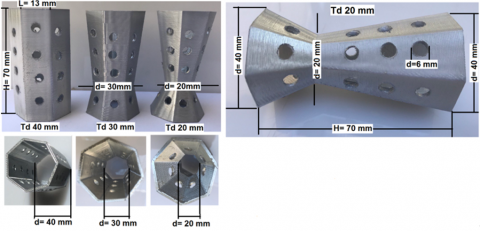
The test apparatus consisted of a 1350 millimeter long, 50 millimeter inner diameter and 1.5 millimeter thick copper pipe. To reduce heat loss, the conveyor (pipe) is shielded with a 25-millimeter thickset asbestos cord. New turbulators were connected to the surface of the inward conveyor. Moreover, the turbulator is formed from metallic element (aluminum) as manifested in Figure 1. The length of the turbulator is designed to be 70 millimeters. An 800-watt group heater was joined to the exterior surface. A variable converter was used to control the power output at constant heat flow, which was induced in the experimental part of the heat converter. On the other hand, A blower 250 W was used to blow air through the test section, and the surface temperature was controlled by connecting eighteen k thermocouples at different points along the test section. Two thermocouples were placed at the inlet and outlet of the conveyor to mark out the temperature of the inlet and outlet air. Temperatures around the examination segment and air temperatures at the inlet and outlet were documented continuously. To detect the descent in pressure and evaluate the friction constant, the pressure valves of the inlet and outlet test section are connected to a digital manometer. Air flow rates were measured using a valve and orifice meter. The test apparatus is shown in Figure 2. The turbulator elements used in this work are heptagonal, each side is 13 mm and 70 mm high. 6 mm diameter holes were made on all faces. Two of the turbulators ones have a waist 20 mm away from one end, one of them has a waist diameter of 20 mm and the other 30 mm, while the third has no waist, as shown in Figure 1 and technical details shown in Table 1. Experiments were conducted in two stages for each of the turbulators. In the first stage, four turbulators were placed inside the tube, with a distance of 214 mm between them, resulting in a pitch ratio (PR) of 4.28, where PR equals the length of the distance between the turbulators divided by the diameter of the test section PR=L⁄D=214⁄50=4.28. While in the second stage, six pieces of turbulators were placed with a distance of 155 mm between them, resulting in a pitch ratio (PR) of 3.1. For each stage of the experiments, the temperature readings of the air entering and exiting the tube were recorded. The average temperature of the tube surface was calculated using eight thermocouples fixed to the tube surface. The pressure drop was also recorded for each reading by digital manometer. The data was then collected and calculations were made based on the equations shown in data reduction.
Figure 1. Turbulators dimension
Figure 2. Diagram exhibit the configuration of the testing apparatus
Table 1. Experimental parameters
|
Test Section |
|
|
Inner diameter |
50 mm |
|
Thickness |
1.5 mm |
|
Length of test section |
1350 mm |
|
Material |
copper |
|
Insulation material |
asbestos cord |
|
Turbulators |
|
|
Material |
Aluminium |
|
High |
70 mm |
|
Large diameter |
40 mm |
|
Thickness |
1 mm |
|
Configurations used |
Td 40 mm Td 30 mm Td 20 mm |
|
Pitch ratio (PR) |
4.28 and 3.1 |
2.1 Data reduction
The ff is determined through:
$\mathrm{f}=\frac{\Delta \mathrm{P}}{\left(\frac{\mathrm{L}}{\mathrm{D}}\right)\left(\frac{\rho \mathrm{u}^2}{2}\right)}$ (1)
Heat absorbed by the air (Qair) is given by:
$\mathrm{Q}_{\mathrm{air}}=\dot{\mathrm{m}} \mathrm{C}_{\mathrm{p}}\left(\mathrm{T}_{\mathrm{o}}-\mathrm{T}_{\mathrm{i}}\right)$ (2)
Regarding the heat balance, the amount of heat transmitted to the air is less than 5% of the total heat input (QVI):
$\left[\frac{\left(\mathrm{Q}_{\mathrm{VI}}-\mathrm{Q}_{\mathrm{air}}\right)}{\mathrm{Q}_{\mathrm{VI}}}\right] \times 100 \%=5 \%$ (3)
The convective HT from the pipe under investigation easilybe determined by:
$\mathrm{Q}_{\mathrm{cov}}=\mathrm{hA}\left[\overline{\mathrm{~T}}_{\mathrm{w}}-\mathrm{T}_{\mathrm{b}}\right]$ (4)
The heat produced by the air is assessed using [32-35]:
$\mathrm{Q}_{\mathrm{air}}=\mathrm{Q}_{\mathrm{cov}}$ (5)
The average HT coefficient given by:
$\mathrm{h}=\dot{\mathrm{m}} \mathrm{C}_{\mathrm{p}}\left[\mathrm{~T}_{\mathrm{o}}-\mathrm{T}_{\mathrm{i}}\right] / \mathrm{A}\left[\overline{\mathrm{~T}}_{\mathrm{w}}-\mathrm{T}_{\mathrm{b}}\right]$ (6)
where: $\left(T_b\right)$ is the definition of mean bulk temperature:
$\mathrm{T}_{\mathrm{b}}=\left[\mathrm{T}_{\mathrm{o}}+\mathrm{T}_{\mathrm{i}}\right] / 2$ (7)
The mean $\bar{T}_w$ is determined by:
$\overline{\mathrm{T}}_{\mathrm{w}}=\left[\sum \mathrm{T}_{\mathrm{w}} / 18\right]$ (8)
Nn can be obtained by:
$\mathrm{Nu}=\left[\mathrm{hD} / \mathrm{k}_{\mathrm{a}}\right]$ (9)
Thermal performance $\eta$ can be defined as the Nn related to the coefficient of friction of the smooth tube [36]:
$\eta=\left[\frac{\mathrm{Nu}}{\mathrm{Nu}_{\mathrm{s}}} /\left(\frac{\mathrm{f}}{\mathrm{f}_{\mathrm{s}}}\right)^{\frac{1}{3}}\right]$ (10)
2.2 Uncertainty analysis
The method of Klein and McClintock [37] was selected to document the uncertainty of critical HT parameters. The results are listed in Table 2. The following formula was used for this calculation:
$\mathrm{W}_{\mathrm{R}}=\left[\left(\frac{\partial \mathrm{R}}{\partial \mathrm{x}_1} \mathrm{~W}_1\right)^2+\left(\frac{\partial \mathrm{R}}{\partial \mathrm{x}_2} \mathrm{~W}_2\right)^2+\cdots\left(\frac{\partial \mathrm{R}}{\partial \mathrm{x}_{\mathrm{n}}} \mathrm{~W}_{\mathrm{n}}\right)^2\right]^{\frac{1}{2}}$ (11)
where, $\mathrm{W}_{\mathrm{R}}$ is referred to the ambiguity in the empirical findings and R indicates the predictor variables $x_1, x_2, \ldots x_n$.
$R=R\left(x_1, x_2, \ldots x_n\right)$
$W_1, W_2, \ldots W_{n}$= the ambiguity in the predictor variables.
Table 2. Parameters uncertainty
|
Apparatus |
Uncertainty |
|
K type thermocouple |
±0.4% |
|
Temperature indicator |
±1% |
|
Inclined manometer |
±5% |
|
Digital manometer |
±5% |
|
Anemometer |
±3% |
|
Current meter |
±0.3% |
|
Voltage meter |
±0.2% |
3.1 Verification of laboratory experiment components
To find out how accurate the test set was, the friction and Nn of the smooth pipe without inserts were compared to those of the standard correlations, as shown in Figure 3(A-B). The Nn recorded by Incropera and DeWitt [38] and Gnielinski [39] were compared in detail. Meanwhile, the friction coefficient outcomes were compared between the Blasius relation [40] and the Petukhov relation [41]. The significant differences between experimental and predicted Nn(s) and Ff values are ±8% and ±7%. The results agreed with the standard relationships and proved the test set's reliability by performing tests with new turbulators.
Dittus-Boeltersformula:
$\mathrm{Nu}=0.023 \mathrm{Re}^{0.8} \operatorname{Pr}^{0.4}$ (12)
Gnielinski's expression:
$\mathrm{Nu}=\left\lceil\frac{(\mathrm{f} / 8)(\mathrm{Re}-1000) \operatorname{Pr}}{1+12.7(\mathrm{f} / 8)^{1 / 2}\left(\operatorname{Pr}^{2 / 3}-1\right)}\right\rceil$ (13)
Blasius Correlation:
$\mathrm{f}=0.316[\mathrm{Re}]^{-0.25}$ (14)
Petukhov Correlation:
$\mathrm{f}=[0.79 \ln \operatorname{Re}-1.64]^{-2}$ (15)
3.2 Effect of the Interior diameter and PR on the Nn
The new geometric turbulator insert and smooth tubes without insert were compared based on the Nn in Figure 4. The HT conditions show the same behavior as the smooth tube. Further, higher Re results in enhanced and stronger turbulent flow. In addition, the tube turbulator insert showed an increase in convective HT compared to the smooth tube. Figure 4 unveils the superior values of the Nn and the lower a waist diameter of 20 mm compared to the others. It is known that a small diameter induces long vortices along the length of the tube [42], so this process can lead to the development of a thermal layer so that the water flows through turbulators; the small inner diameter of the corrugation improves the observations the flow velocity between the core and the surface wall. It is essential to mention that a flow replaced the fluid near the surface in the core due to the increase in temperature gradients along the conveyor pipes inside the walls, which enhances HT [43, 44]. Additionally, Figure 4 demonstrates that the Nn increases when the PR of the turbulators decreases. Where the maximum Nusselt value in the smooth tube at the highest Re 30269 was 70, while the Nusselt values when using the turbulents Td 40 mm, Td 30 mm and Td 20 mm at the pitch ratio 4.28 were 90, 93 and 98 respectively but at the pitch ratio 3.1 were 100, 108 and 115 respectively for the same Re 30269.
Furthermore, the improvement in convective heat transfer was more noticeable in the innovative geometric turbulator inserts compared to the plain tube. The results indicate that the Nn increases by 42%, 54%, and 65% in the tube with innovative geometric turbulator inserts (Td 40 millimeter, Td 30 millimeter, and Td 20 millimeter) with PR=3.1 respectively compared to the normal conveyor. This indicates that utilizing a Td of 20 millimeters results in a substantial increase in the HT.
Figure 3. The Nn and Ff for smooth tubes exhibit both experimental and prediction correlations with the Re
Figure 4. Behaviorof the Nusselt factor against the Re
3.3 Internal diameter and PR effecton coefficient of friction
Figure 5 unveils the alteration of the friction constant as a function of the Re for a smooth pipe fitted with innovative geometric turbulator inserts. The coefficient of friction decreases as the Re increases and also increases when using turbulents, especially at a low pitch ratio. The reason for this is that the flow of the flowing fluid faces an obstruction in its flow, which in turn leads to an increase in the friction of the fluid with the surface of the pipe and the surfaces of the turbulents.
Figure 5. Behaviorof the friction parameter against the Re
In addition, it may be observed that there is a conspicuous augment in friction coefficients when using turbulators with dimensions of Td 40 millimeter, Td 30 millimeter, and Td 20 millimeter and pitch ratios (PR) of 3.1 and 4.28 compared to the friction of traditional tubes. The following results were shown for the friction coefficient values, which reached 0.029 for the smooth tube at the highest Re, while the friction coefficient values when using the Td 40 mm, Td 30 mm and Td 20 mm turbulents at a pitch ratio of 4.28 and at the same Re value were 0.034, 0.035 and 0.037 respectively, while the values at a pitch ratio of 3.1 were 0.039, 0.042 and 0.044 respectively.
It is also crucial to understand that non-elastic shear forces cause the formation of secondary inflow in new geometrical composites. Therefore, the fluid moves against the pipe wall, causing an axial velocity current in the pipe. Indeed, the secondary inflow created by the new geometrical turbulence forces the water outward to balance the momentum, leading to increased flow pressure [45]. Concurrently, as the PR is reduced, the friction coefficient increases in new-geometry turbulators. This situation is similar to the Nn. It was revealed that the Ff(s) were 35%, 45%, and 52% higher in the pipe installed with PR=L/D=3.1 insert (Td 40 millimeter, Td 30 millimeter, and Td 20 millimeters). Nevertheless, Re from the range (13968-30264) were observed.
3.4 The impact of the internal diameter and PR on thermal performance (η)
Figure 6 shows the $\eta$ versus Re for a tube with turbulators Td 40 mm, Td 30 mm and Td 20 mm and pitch ratio pitch ratio 3.1 and 4.28. An opposite correlation was seen between the Thp factor (η) and the Reynolds numeral, indicating a decrease thermal efficiency with an increasing Re. This phenomenon can be explained by the increasing depth of the thermal barriers as the Re increases. The existence of turbulence in the thermal barrier layers was detected at lower Re. The increase in Nn was more pronounced than the increase in friction losses making η > 1.0. The reason for that the fluid flows through the holes distributed on all surfaces of the turbulator tube and the small distance between the turbulator leads to an increase in the intensity of the vortex motion, which in turn leads to an increase in the HT rate between the tube surface and the fluid flow, and thus leads to an increase in the $\eta$. The highest value of the $\eta$ at the lowest value of Re 13968 for the three turbulators Td 40 mm, Td 30 mm and Td 20 mm at pitch ratio 4.28 were 1.2, 1.23 and 1.28 respectively, while the lowest value of the $\eta$ at the highest value of Re 30268 were 1.18, 1.19 and 1.23 respectively. As for the values of the $\eta$ for the PR of 3.1 for the lowest Re for the three turbulators Td 40 mm, Td 30 mm and Td 20 mm, were (1.35, 1.39 and 1.47) respectively, while for the highest Re were 1.26, 1.3 and 1.4 respectively. The highest value of the η=1.47 indicates a significant improvement in the HT process. This means that the use of tube inserts has an important effect in reducing the size of the HE device and in saving energy, thus eliminating the need for an additional external power source. This technique also benefits from reducing material deposits on the pipe wall due to good mixing of the fluid during flow through these inserts also reduces pollution . This is the most important implications of the findings of this study, especially since these equipment has many uses in industrial systems that require large amounts of energy. For these reasons, it is necessary to improve the operation of the HE.
Figure 6. Behavior of the η against the Re
Figure 7. Empirical against anticipated values of the (Nn) and friction coefficient
3.5 Practical correlations enhancements
Experimentally, the Nn and ff correlation factors were improved and verified by practical outcomes. Such a relationship is proposed for new geometric corporations that use air as the working fluid.
$\begin{gathered}\operatorname{Pr} \approx 0.7 \text { at } \mathrm{Re}=13968-30264, \mathrm{PR}=3.1-4.28, \text { and } \mathrm{d} =2-4 . \\ \mathrm{Nu}=0.12 \mathrm{Re}^{0.72} \operatorname{Pr}^{0.4} \mathrm{PR}^{-0.25}(1-\mathrm{d})^{0.45}\end{gathered}$ (16)
$\mathrm{f}=0.553 \mathrm{Re}^{-0.19} \mathrm{PR}^{-0.47}(1-\mathrm{d})^{0.31}$ (17)
Figure 7 illustrates a comparison between the practical and anticipated values of Nn(s) and friction, revealing a little discrepancy. Moreover, most of the experimental findings lie within the ( ±8 - ±9)% range of the projected Nu and f.
The present work using modern turbulators is compared with previous studies conducted on improving the thermal characteristics of HE. Figure 8 shows a comparison of the Nn found in this study with those found in earlier research that used different kinds of inserts, like twisted film inserts [46], helical tapes [47], warped tapes [48], and five-pointed star turbulators [10]. It appears from the results that the Nusselt values for this study are higher than [10] which used five-pointed star turbulators for Reynolds values up to 1600 and also higher than [47] which used helical tapes for Reynolds values exceeding 2400 because the tendency of study [47] is towards a decline for high Reynolds values while the tendency of this study is towards an increase which is consistent with other studies in which the tendency of the plot is towards an increase for high Reynolds values.
Figure 8. Nn comparison against previous research
An experimental study on a tube HE was carried out using modern perforated turbulators to verify the improvement of the thermal characteristics of the HE. The effect of pitch ratio, increasing Re, friction coefficient and performance coefficient were examined. Results are summarized as follows:
1. Increasing the Re leads to increasing the Nu, as with increasing velocity the HT coefficient increases, and the friction coefficient also increases with increasing Reynolds number.
2. The inserted turbulators leads to an increase in the HT coefficient higher than the smooth tube, as it was found that the Nu has improved by a percentage of up to 64% as the highest value. The coefficient of friction also increases by up to 51.7% as the highest value.
3. It was found that the pitch ratio has a great effect on enhancing HT, as the Nu value of turbulators (Td 40 mm, Td 30 mm, and Td 20 mm) for PR=3.1 found to be 11.1%, 16.1% and 17.3% higher, respectively, compared to pitch PR=4.28. It also leads to an increase in the coefficient of friction in case PR= 3.1 by 14.7%, 20% and 18.9% compared to PR=4.28.
4. The performance factor in all cases is more than one and increases as the pitch ratio decreases, and its highest value was 1.47. This means that the present study of turbulators has clear utility in practical applications.
5. The empirical correlations between Nu and ff were satisfactory for the experimental results. The deviations were 8% for the Nu and 9% for the f.
|
A |
surface area |
|
Cp |
specific heat |
|
d |
diameter m |
|
F |
friction facto |
|
h |
HT factor |
|
HE |
heat exchanger |
|
HT |
heat transfer |
|
k |
thermal conductivity |
|
L |
length m |
|
$\dot{m}$ |
mass flow |
|
T |
temperature |
|
u |
velocity of air |
|
Q |
heat transfer |
|
P |
plain tube |
|
PR |
pitch ratio |
|
Thp |
thermal performance |
|
Re |
Reynolds factor |
|
Pr |
Prandtl factor |
|
Nu |
Nusselt factor |
|
Subscripts |
|
|
i |
inner |
|
o |
outer |
|
a |
air |
|
s |
smooth tube |
|
Greek symbols |
|
|
$\Delta \mathrm{P}$ |
pressure drop |
|
$\rho$ |
density |
|
$\eta$ |
thermal performance |
[1] Hashim, W.M., Hoshi, H.A., Al-Salihi, H.A. (2019). Enhancement the performance of swirl heat exchanger by using vortices and NanoAluminume. Heliyon, 5(8): e02268.
[2] Altaie, A., Hasan, M.R., Rashid, F.L. (2014). Numerical heat transfer and turbulent flow in a circular tube fitted with opened rings having square cross section. Journal of Basic and Applied Scientific Research, 4(11): 28-36.
[3] Rashid, F.L., Altaie, A., Hasan, M.R. (2014). Numerical investigation of heat transfer enhancement in a circular tube using ribs of separated ports assembly. European Scientific Journal, 2: 172-183.
[4] Altaie, A., Hasan, M.R., Rashid, F.L. (2015). Numerical investigation of heat transfer enhancement in a circular tube with rectangular opened rings. Bulletin of Electrical Engineering and Informatics, 4(1): 18-25. https://doi.org/10.11591/eei.v4i1.331
[5] Altaie, A., Hasan, M.R., Rashid, F.L. (2015). Heat transfer enhancement in a circular tube using ribs with middle arm. Elixir International Journal, 5(2): 235804712.
[6] Altaie, A., Hasan, M.R., Rashid, F.L. (2015). Numerical investigation in a circular tube to enhance turbulent heat transfer using opened rings-triangular cross section. Journal of Babylon University/Engineering Sciences, 23(3): 798-807.
[7] Al-Jibory, M.W., Rashid, F.L., Hussein, H.Q. (2018). Heat transfer augmentation in gas turbine blade rectangular passages using circular ribs with fins. Journal of University of Babylon for Engineering Sciences, 26(1): 247-258.
[8] Al-Jibory, M.W., Rashid, F.L., Talib, S.M. (2018). Numerical investigation of heat transfer enhancement in ribbed elliptical passage. Journal of Engineering and Applied Sciences, 13(17): 7223-7234.
[9] Hoshi, H.A., Abed, A.H., Al-Salihi, H.A., Rashid, F.L., Hussain, A.A. (2024). Heat transfer enhancement in a circular tube with novel geometric turbulator inserts. Mathematical Modelling of Engineering Problems, 11(4): 996-1004.
[10] Hoshi, H.A., Shehab, W.Y., Khlief, A.K., Rashid, F.L., Hussain, A.A. (2024). Heat transfer improvement using three types novel turbulators inserts with two pitch ratios in double pipe heat exchanger. Mathematical Modelling of Engineering Problems, 11(6): 1593-1600. https://doi.org/10.18280/mmep.110620
[11] Rashid, F.L., Al-Jibory, M.W., Talib, S.M. (2018). Numerical investigation of heat transfer augmentation in elliptical passage with different rib geometries and aspect ratios. International Journal of Mechanical Engineering and Technology, 9(13): 1390-1409.
[12] Rashidi, S., Zade, N.M., Esfahani, J.A. (2017). Thermo-fluid performance and entropy generation analysis for a new eccentric helical screw tape insert in a 3D tube. Chemical Engineering and Processing: Process Intensification, 117: 27-37. https://doi.org/10.1016/j.cep.2017.03.013
[13] Roy, S., Saha, S.K. (2015). Thermal and friction characteristics of laminar flow through a circular duct having helical screw-tape with oblique teeth inserts and wire coil inserts. Experimental Thermal and Fluid Science, 68: 733-743. https://doi.org/10.1016/j.expthermflusci.2015.07.007
[14] Nakhchi, M.E., Esfahani, J.A. (2018). Cu-water nanofluid flow and heat transfer in a heat exchanger tube equipped with cross-cut twisted tape. Powder Technology, 339: 985-994. https://doi.org/10.1016/j.powtec.2018.08.087
[15] Abolarin, S.M., Everts, M., Meyer, J.P. (2019). The influence of peripheral u-cut twisted tapes and ring inserts on the heat transfer and pressure drop characteristics in the transitional flow regime. International Journal of Heat and Mass Transfer, 132: 970-984. https://doi.org/10.1016/j.ijheatmasstransfer.2018.12.051
[16] Nakhchi, M.E., Hatami, M., Rahmati, M. (2020). Experimental investigation of heat transfer enhancement of a heat exchanger tube equipped with double-cut twisted tapes. Applied Thermal Engineering, 180: 115863. https://doi.org/10.1016/j.applthermaleng.2020.115863
[17] Liaw, K.L., Kurnia, J.C., Sasmito, A.P. (2021). Turbulent convective heat transfer in helical tube with twisted tape insert. International Journal of Heat and Mass Transfer, 169: 120918. https://doi.org/10.1016/j.ijheatmasstransfer.2021.120918
[18] Zhang, H., Nunayon, S.S., Jin, X., Lai, A.C. (2022). Pressure drop and nanoparticle deposition characteristics for multiple twisted tape inserts with partitions in turbulent duct flows. International Journal of Heat and Mass Transfer, 193: 121474. https://doi.org/10.1016/j.ijheatmasstransfer.2021.121474
[19] Bhuiya, M.M.K., Roshid, M.M., Talukder, M.M.M., Rasul, M.G., Das, P. (2020). Influence of perforated triple twisted tape on thermal performance characteristics of a tube heat exchanger. Applied Thermal Engineering, 167: 114769. https://doi.org/10.1016/j.applthermaleng.2019.114769
[20] Famileh, I.Z., Esfahani, J.A. (2017). Experimental investigation of wet flue gas condensation using twisted tape insert. International Journal of Heat and Mass Transfer, 108: 1466-1480. https://doi.org/10.1016/j.ijheatmasstransfer.2017.01.001
[21] Kamble, D.A., Joshi, P., Yadav, R.J., Kore, S. (2017). Investigation of heat transfer coefficient for non-circular duct twisted tape insert. Thermal and Fluids Engineering Conference 18, Second Issue.
[22] Zheng, G., Zhang, W., Man, C., Sun, P. (2021). Thermal characteristics of a heat exchanger tube fitted with different peripherally-cut twisted tape inserts in laminar flow. Heat Transfer Research, 52(12): 29-42. https://doi.org/10.1615/HeatTransRes.2021036646
[23] Kumar, B., Patil, A.K., Kumar, M. (2021). Second law analysis of heat exchanger tube fitted with twisted tape insert having multiple V cuts and perforations. Heat Transfer Research, 52(7): 17-34. https://doi.org/10.1615/HeatTransRes.2021036514
[24] Hamid, K.A., Azmi, W.H., Mamat, R., Sharma, K.V. (2019). Heat transfer performance of TiO2-SiO2 nanofluids in a tube with wire coil inserts. Applied Thermal Engineering, 152: 275-286. https://doi.org/10.1016/j.applthermaleng.2019.02.083
[25] Azmi, W.H., Hamid, K.A., Ramadhan, A.I., Shaiful, A.I.M. (2021). Thermal hydraulic performance for hybrid composition ratio of TiO2-SiO2 nanofluids in a tube with wire coil inserts. Case Studies in Thermal Engineering, 25: 100899. https://doi.org/10.1016/j.csite.2021.100899
[26] Ahirwar, B.K., Kumar, A. (2024). Effect of wire coil inserts on heat transfer enhancement and fluid flow characteristics of a double-pipe heat exchanger. Journal of Thermal Analysis and Calorimetry, 149(7): 3027-3042. https://doi.org/10.1007/s10973-024-12889-z
[27] Keklikcioglu, O., Ozceyhan, V. (2016). Experimental investigation on heat transfer enhancement of a tube with coiled-wire inserts installed with a separation from the tube wall. International Communications in Heat and Mass Transfer, 78: 88-94. https://doi.org/10.1016/j.icheatmasstransfer.2016.08.024
[28] Sontakke, S., Patel, P., Sharma, A., Singh, M., Hardik, B.K. (2023). Experimental and numerical investigation of heat transfer enhancement with twisted tape insert. Heat Transfer Research, 54(14): 17-42. https://doi.org/10.1615/HeatTransRes.2023045756
[29] Abbaspour, M., Mousavi Ajarostaghi, S.S., Hejazi Rad, S.A., Nimafar, M. (2021). Heat transfer improvement in a tube by inserting perforated conical ring and wire coil as turbulators. Heat Transfer, 50(6): 6164-6188. https://doi.org/10.1002/htj.22167
[30] Chaurasia, S.R., Sarviya, R.M. (2023). Experimental thermal performance analysis of fluid flow in a heat exchanger pipe with novel double strip helical screw tape inserts for utilization of energy resources. Energy Sources, Part A: Recovery, Utilization, and Environmental Effects, 45(2): 4268-4281. https://doi.org/10.1080/15567036.2019.1669741
[31] Liu, P., Zheng, N., Shan, F., Liu, Z., Liu, W. (2018). Heat transfer enhancement for laminar flow in a tube using bidirectional conical strip inserts. International Journal of Heat and Mass Transfer, 127: 1064-1076. https://doi.org/10.1016/j.ijheatmasstransfer.2018.07.128
[32] Promvonge, P., Eiamsa-Ard, S. (2007). Heat transfer and turbulent flow friction in a circular tube fitted with conical-nozzle turbulators. International Communications in Heat and Mass Transfer, 34(1): 72-82. https://doi.org/10.1016/j.icheatmasstransfer.2006.08.003
[33] Anvari, A.R., Lotfi, R., Rashidi, A.M., Sattari, S. (2011). Experimental research on heat transfer of water in tubes with conical ring inserts in transient regime. International Communications in Heat and Mass Transfer, 38(5): 668-671. https://doi.org/10.1016/j.icheatmasstransfer.2011.03.016
[34] Eiamsa-ard, S., Promvonge, P. (2006). Experimental investigation of heat transfer and friction characteristics in a circular tube fitted with V-nozzle turbulators. International Communications in Heat and Mass Transfer, 33(5): 591-600. https://doi.org/10.1016/j.icheatmasstransfer.2006.02.022
[35] Ozceyhan, V., Gunes, S., Buyukalaca, O., Altuntop, N. (2008). Heat transfer enhancement in a tube using circular cross sectional rings separated from wall. Applied Energy, 85(10): 988-1001. https://doi.org/10.1016/j.apenergy.2008.02.007
[36] Chokphoemphun, S., Pimsarn, M., Thianpong, C., Promvonge, P. (2015). Thermal performance of tubular heat exchanger with multiple twisted-tape inserts. Chinese Journal of Chemical Engineering, 23(5): 755-762. https://doi.org/10.1016/j.cjche.2015.01.003
[37] Kline, S.J. (1963). Describing uncertainties in single-sample experiments. Mechanical Engineering, 75: 3-8.
[38] Incropera, F.P., DeWitt, D.P. (2002). Introduction to Heat Transfer. fourth ed. John Wiley & Sons, New York, 459-463.
[39] Gnielinski, V. (1976). New equations for heat and mass transfer in turbulent pipe and channel flow. International Chemical Engineering, 16(2): 359-367.
[40] White, F.M. (2011). Fluid Mechanics. Seventh ed., McGraw-Hill, New York.
[41] Petukhov, B.S. (1970). Heat transfer and friction in turbulent pipe flow with variable physical properties. Advances in Heat Transfer, 6: 503-564. https://doi.org/10.1016/S0065-2717(08)70153-9
[42] Biswas, G., Chattopadhyay, H., Sinha, A. (2012). Augmentation of heat transfer by creation of streamwise longitudinal vortices using vortex generators. Heat Transfer Engineering, 33(4-5): 406-424. https://doi.org/10.1080/01457632.2012.614150
[43] Gentry, M.C., Jacobi, A.M. (2002). Heat transfer enhancement by delta-wing-generated tip vortices in flat-plate and developing channel flows. ASME Journal of Heat and Mass Transfer, 124(6): 1158-1168.
[44] Biswas, G., Torii, K., Fujii, D., Nishino, K. (1996). Numerical and experimental determination of flow structure and heat transfer effects of longitudinal vortices in a channel flow. International Journal of Heat and Mass Transfer, 39(16): 3441-3451. https://doi.org/10.1016/0017-9310(95)00398-3
[45] Hsieh, S.S., Wu, F.Y., Tsai, H.H. (2003). Turbulent heat transfer and flow characteristics in a horizontal circular tube with strip-type inserts. Part I. Fluid mechanics. International Journal of Heat and Mass Transfer, 46(5): 823-835. https://doi.org/10.1016/S0017-9310(02)00353-8
[46] Eiamsa-Ard, S., Promvonge, P. (2010). Performance assessment in a heat exchanger tube with alternate clockwise and counter-clockwise twisted-tape inserts. International Journal of Heat and Mass Transfer, 53(7-8): 1364-1372. https://doi.org/10.1016/j.ijheatmasstransfer.2009.12.023
[47] Hong, Y., Du, J., Wang, S., Huang, S.M., Ye, W.B. (2018). Effect of decaying swirl flow on tubular turbulent heat transfer enhancement by using short length helical tapes. Chemical Engineering Research and Design, 138: 1-12. https://doi.org/10.1016/j.cherd.2018.08.009
[48] Tamna, S., Kaewkohkiat, Y., Skullong, S., Promvonge, P. (2016). Heat transfer enhancement in tubular heat exchanger with double V-ribbed twisted-tapes. Case Studies in Thermal Engineering, 7: 14-24. https://doi.org/10.1016/j.csite.2016.01.002