Olarewaju T. Oginni![]() | Bukola B. Bolaji*
| Bukola B. Bolaji*![]() | Adedotun O. Adetunla
| Adedotun O. Adetunla![]() | Chan Choon Kit
| Chan Choon Kit![]()
© 2024 The authors. This article is published by IIETA and is licensed under the CC BY 4.0 license (http://creativecommons.org/licenses/by/4.0/).
OPEN ACCESS
Ensuring the quality of fresh frozen plasma is crucial for clinical transfusions due to its limited storage duration. Cascade refrigeration systems (CRS) represent a promising and efficient technology model capable of facilitating ultra-low temperature (ULT) applications and maintaining them during fresh plasma storage. This study focuses on the design and performance evaluation of a vapor-compression CRS aimed at optimizing plasma processing efficiency and safeguarding plasma proteins to extend their shelf life. The selection of refrigerants R404A and R410A is based on a comprehensive analysis of different refrigerants' characteristics for short-term freezing applications, targeting low-temperatures. The system successfully achieves the desired evaporator ULT of -35℃. Evaluation involves utilizing 4 kg of fresh human blood plasma for 120 minutes after collection via a centrifugal-based apheresis machine. Protein integrity tests are conducted using a refractometer before and after freezing to assess plasma preservation. The system's capability to extend plasma shelf life is further examined after 72 hours of temperature-controlled storage. The cooling chamber maintained stable frozen plasma protein concentrations of 10 g, 0.75 g, and 0.6 g per 250 g, with a system efficiency of 75%. The equipment extends the shelf life of blood plasma, manages heat-sensitive medications effectively, and enhances healthcare management efficacy.
design analysis, rapid freezing, blood plasma, refrigeration, biomedical, efficient
Ultra-low temperature refrigeration is essential across various fields, including research, industry, and home use. It is critical for the storage of biological materials such as biobanks, proteins, DNA, vaccines, antibodies, small molecules, and enzymes. Additionally, refrigeration is fundamental in preserving perishable foods and supporting food processing, storage, and transportation by keeping temperatures low [1]. The cascade refrigeration system is highly effective for low-temperature applications, offering an energy-efficient solution that lowers operational costs for quick freezing and consistent temperature maintenance. It operates effectively at extremely low temperatures, with evaporating temperatures ranging from -18℃ to -35℃, making it ideal for frozen storage cabinets. This system addresses critical issues related to heat-sensitive items like vaccines and blood products, which demand reliable storage and robust refrigeration systems. The cascade refrigeration system emerges as a leading technology for low-temperature applications, offering energy-efficient cycles that reduce operational costs while achieving rapid freezing and sustaining the desired storage temperature [2]. Operating in frigid conditions, this system maintains evaporating temperatures for frozen cabinets ranging from -18℃ to -35℃. It addresses various challenges related to heat-sensitive products like vaccines and blood products, necessitating reliable storage enclosures and robust refrigeration systems [3]. Employing one refrigerant to condense the primary refrigerant operating at the desired evaporator, the cascade system efficiently operates in achieving very low temperatures. Its applications span across diverse fields, including medical, biological, commercial, agricultural, and industrial sectors, garnering attention for its multitude of benefits [4].
Certain essential medicines and vaccines require uninterrupted cold chains to maintain their integrity from production to administration. By storing vaccines at low temperatures, the need for additional preservatives is minimized, reducing the risk of bacterial growth and ensuring efficacy [5]. The global distribution of vaccines involves significant logistical hurdles, requiring meticulously managed temperature-controlled conditions to effectively store, handle, and transport these crucial products [6]. Additionally, a strong healthcare system relies on having a reliable and secure supply of blood and blood products, as well as ensuring the safety of transfusion services. Transfusion medicine is a vital multi-disciplinary branch of medicine that specializes in the proper use and management of blood products for treatment and prevention of disease. The field deals with safety measures, shortage and administration techniques [7].
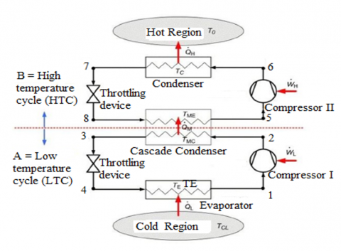
However, the shortage experienced was due to inadequate preparation, global problems of plasma and importation safety, medical challenges of plasma administration, problem of frozen plasma within 8hours to 24hours of collection that made blood product unavailable and posed a real global challenge in transfusion medicine [8]. Plasma (convalescent) transfusion had therapeutic role during covid-19 as there was no specific preventive and therapeutic options (vaccine). A cascade system is composed of two distinct single-stage refrigeration systems that operate independently but sequentially. One system handles lower evaporating temperatures to generate cooling, while the other works at a higher evaporating temperature [9]. The two distinct systems are interconnected through a cascade condenser, which transfers heat from the condenser of the lower system to the evaporator of the higher system. The cascade cycle is utilized to achieve a wide temperature range between the low and high temperatures, thereby improving the Coefficient of Performance (COP) of the refrigeration process. Additionally, selecting refrigerants with increasingly lower boiling points helps manage appropriate evaporator and condenser pressures across different temperature ranges. The need for accurate system parameter simulations for effective analysis was highlighted by Ratio et al. [9] focus was on simulating a two-stage cascade refrigeration system model, followed by the validation and assessment of this model using experimental data. The study began with designing a two-stage cascade refrigeration system using R22/R32, followed by experiments to acquire operational parameters for validation and evaluation of system components. The design aimed to achieve suitable temperature and pressure conditions for simulation purposes. The experimental results yielded a COP value of 1.018 at an evaporator temperature of -40℃. Analysis revealed that the actual performance of the two-stage cascade refrigeration system was below expectations due to suboptimal heat exchange in the cascade heat exchanger. Figure 1 provides a schematic overview of the cascade refrigeration system, highlighting its components, which include a lower-temperature (pressure) cycle and a higher-temperature (pressure) cycle, connected by a cascade condenser. Key components of the cascade system include a low-temperature compressor, a high-temperature compressor, a condenser, an evaporator, a cascade condenser (heat exchanger), and expansion devices for both temperature cycles [10, 11].
Figure 1. Schematic diagram of a simple cascade refrigeration system
Blood plasma is notoriously difficult to store as it requires a stable long-term, extremely low-temperature application. It is challenging to efficiently monitor fresh plasma and maintain the frozen plasma's quality in storage for safety measures of quality assurance over an extended period of time due to a number of issues with the medical freezers that are currently in the market and other techniques. The lack of a mobile machine at the donation centre for temperature-controlled fresh plasma and instant freezing, delayed freezing periods, frozen plasma lumps, and insensitive temperature-controlled storage systems are some of these issues that need to be addressed. Nonetheless, the cascade refrigeration system stands out as a highly effective and efficient technology for ensuring reliable access to safe and adequate supplies of blood products in ultra-low temperature applications. Research has revealed that blood donation centers do not have a transit refrigeration system for processing plasma right away. The research thus introduces a design mobile system to support the optimization of fresh blood plasma processing and efficient storage for secure transportation via healthcare facilities. This is accomplished by taking into account the physiochemical characteristics of the product that will be held at a controlled freezing temperature. The methodology and result will be discussed extensively.
2.1 Materials selection
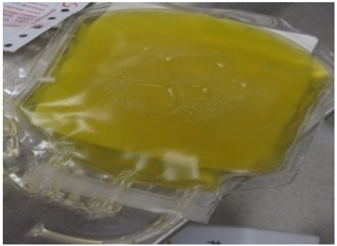
Blood's liquid component is called blood plasma. Plasma, serving as the conveyance system, delivers essential nutrients to the cells of the body's organs and transports waste generated by cellular metabolism to be eliminated by the kidneys, liver, and lungs. The image is a yellowish liquid as shown in Figure 2. Table 1 characterised the physiochemical properties of blood plasma ranging appearance, heat capacity, boiling and melting points, freezing and storage temperatures among others.
Figure 2. The human fresh frozen plasma
2.2 Design parameters
The following parameters were considered for the design of a two-stage cascade refrigeration system.
For the Low Temperature Cycle (process 1-2-3-4).
The Refrigerant is R410A, Evaporator temperature, TEL=-35℃, Evaporator pressure, PEL=0.2196MPa, Condenser temperature, TCL=18℃ and Condenser pressure, PCL=1.3613MPa.
For the High Temperature Cycle (process 5-6-7-8).
The Refrigerant is R404A, Evaporator temperature, TEH=12℃, Evaporator pressure, PEH=0.8772MPa, Condenser temperature, TCH=40℃, Condenser pressure, PCH=1.8148MPa, Ambient temperature, TAP=35℃, Refrigeration capacity, QR=1kW and Temperature overlap, TO=TCL-TEH=18℃-12℃=6℃.
Table 1. Summary of physiochemical properties of blood plasma
|
Properties |
Values |
|
Appearance |
Barely yellow to dark yellow |
|
Specific heat capacity above freezing point |
3.93J/g-℃ |
|
Specific heat capacity below freezing point |
2.0J/kg |
|
Latent heat |
307J/kg |
|
Melting point |
-0.568–0.512℃ |
|
Boiling point |
Approximately 0.158℃ |
|
Density |
Approximately 1025Kg/m3 or 1.025 g/ml |
|
Freezing point |
At-0.59℃ |
|
Storage temperature |
-18℃ or colder |
|
Protein’s content |
It is 7% protein. |
|
Mineral salts |
It contains 1% mineral salts |
|
Water content |
Blood plasma has 91% to 92% amount of water |
2.2.1 Refrigeration selection
The selection of R410A and R404A refrigerants in this study is purposely targeted rapid freezing and storing blood plasma proteins for shelf-life increase based on the refrigerants thermophysical properties of low-temperature values as shown in Table 2. The following factors were considered among others such as better mass flow rate, high refrigerating effect, high discharge pressure, short time for low-temp. attainment, better C.O.P, affordability (cheap) and availability and existing refrigeration components favour R410A and R404A [2, 3, 12, 13].
Figure 3. CAD overview of the cascade system and blood plasma assembly
In many industries and medical sectors, the time to achieve the desired temperature is paramount utmost. Refrigerants R410A and R404A were chosen for rapid homogeneous freezing and storing fresh blood plasma in terms of refrigerating Effect and Discharge Pressure, R410A is slightly better than that of R22, achieving low-temperature in short time, R404A is recommended domestic refrigeration purpose, R410A is preferred over R22, mass flow rate, R404A is better when compared with R410A and R22, and thermodynamic properties for all refrigerants [14-17]. The CAD overview of the dev eloped system is presented in Figure 3.
Table 2. Refrigerants’ main properties of R404A and R410A [12, 13]
|
Refrigerant |
Units |
R410A |
R404A |
||
|
Type |
|
HFC |
HFC |
||
|
Component |
|
R125 and R32 |
R125, R143a and R134a |
||
|
Composition |
% by weight |
50% and 50% |
52%, 44% and 4% |
||
|
Molecular mass |
|
72.6 |
97.6 |
||
|
ODP |
|
0 |
0 |
||
|
Critical temperature |
℃ |
71.8 |
72.1 |
||
|
Critical pressure |
MPa |
48.9 |
37.3 |
||
|
Boiling point |
℃ |
-51.6 |
-46.6/-45.8 |
||
|
Temperature |
℃ |
-30 |
30 |
-30 |
30 |
|
Sat. pressure |
kPa |
270 |
1877 |
204.95 |
1426 |
2.2.2 Heat load determination
In this study, the heat load is segmented into five specific categories: Heat conducted through the walls of the cooling area, thermal load from the products, heat influx from infiltration, heat absorbed from packaging, and operational thermal loads.
Heat transfer via evaporator walls. Wall heat gain, or wall leakage load, refers to the rate at which heat is transferred through the walls of the refrigerated space from outside to inside via conduction. This heat transfer through the evaporator walls depends largely on the temperature difference between the interior and exterior of the chamber, as well as factors such as the walls' thermal resistance, thickness, and surface area. Therefore, these factors are carefully considered in the design.
The external dimensions are 1.03 meters in length, 0.65 meters in width, and 0.50 meters in depth.
The internal dimensions are 0.62 meters in length, 0.49 meters in width, and 0.42 meters in depth.
Ambient product temperature, TAP=35℃=08 K
Temperature of frozen plasma, TFP=-35℃=238 K
Change in temperature, $\Delta T$=TAP–TFP=(308-238) K=70 K
The plate material is stainless steel sheet (0.001 m thick)
The insulating material is Styrofoam (0.1m thick)
The surface area covered by the insulator, Ains is:
$\begin{gathered}\mathrm{A}_{\mathrm{ins}}=\{[(1.03 \times 0.65)+(1.03 \times 0.50)+(0.65 \times 0.50)] \times 2\} \mathrm{m}^2 \\ \mathrm{~A}_{\text {ins}}=3.02 \mathrm{~m}^2\end{gathered}$ (1)
Hence, the speed at which heat conducts through the refrigerated walls space, $\dot{Q}_{\text {cond}}$ is defined as contained in [16].
$\dot{Q}=\mathrm{UA} \Delta T$ (2)
$\begin{gathered}\dot{Q}_{\text {cond}}=(0.314 \times 3.02 \times 70) \mathrm{W} \\ \dot{Q}_{\text {cond}}=0.0664 \mathrm{~kW}\end{gathered}$ (3)
The amount of heat transferred, denoted as $Q_c$, through the evaporator walls during three hours of continuous operation is approximated in the following manner:
$Q_{\text {cond}}=\dot{Q}_{\text {cond }} t$ (4)
$Q_{\text {cond}}=717.12 \mathrm{~kJ}$ (5)
The product heat load. The thermal discharge from the items intended for storage holds significant importance, particularly in cold storage facilities. In this context, the product load refers to the collective mass of the blood plasma (250 ml) and its bag each.
The cooling chamber is designed to take in 16 pieces of blood plasma bags at a time.
$m_{t p}=0.256 \times 16=4.1 \mathrm{~kg}$ (6)
Therefore, the capacity of the evaporator (cooling chamber load on isolation) is 4.1 kg of blood plasma bags.
In other to determine the product load ($Q_{p r o d}$) of the cascade system, the load to be considered in the cold storages are divided into three groups via.
a. Chilling Load above Freezing, $Q_c$
This refers to the heat required to cool blood plasma from 30℃ to -0.59℃, the temperature at which the plasma begins to freeze. The chilling load above the freezing point is influenced by factors such as the mass of the product, its average specific heat above freezing, the initial temperature of the product, the target final temperature, and the duration of the chilling process.
$\mathrm{Q}_{\mathrm{c}}=\mathrm{m}_{\mathrm{tp}} \mathrm{c}_{\mathrm{p}} \Delta \mathrm{T}_1$ (7)
$\mathrm{Q}_{\mathrm{c}}=573.46 \mathrm{~kJ}$ (8)
b. Cooling load below freezing, $Q_{b f}$
This represents the heat acquired during additional cooling, transitioning from -0.59℃ to -35℃. The cooling requirement below freezing is contingent upon factors such as the product's mass, average specific heat of the items below freezing, current storage temperature, desired freezing temperature (the temperature within the refrigerated space), and the duration of cooling.
$\mathrm{Q}_{\mathrm{bf}}=\mathrm{m}_{\mathrm{fp} \times} \mathrm{C}_{\mathrm{fp} x} \Delta \mathrm{~T}_2$ (9)
$\mathrm{Qbf}_{\mathrm{bf}}=282.16 \mathrm{~kJ}$ (10)
c. Freezing load, $Q_f$
This refers to the heat absorbed during the transition of blood plasma from -0.59℃ to frozen plasma (latent heat of freezing). The freezing requirement is influenced by factors including the product's mass, its latent heat of freezing, and the duration of freezing.
$\mathrm{Qf}_{\mathrm{f}}=\mathrm{m}_{\mathrm{fp}} \mathrm{L}_{\mathrm{fp}}$ (11)
$\mathrm{Q}_{\mathrm{f}}=1258.70 \mathrm{~kJ}$ (12)
Therefore, the product heat load of the cascade system, $Q_{\text {prod }}$ is calculated as follows:
$\mathrm{Q}_{\text {prod}}=\mathrm{Q}_{\mathrm{c}}+\mathrm{Q}_{\mathrm{f}}+\mathrm{Q}_{\mathrm{bf}}$ (13)
$\mathrm{Q}_{\text {prod }}=195.77 \mathrm{~W}$ (14)
Heat increase due to infiltration. During the regular operation of a refrigerated facility, doors are occasionally opened to facilitate the movement of goods. Infiltration load stands as a significant factor within refrigeration systems. Infiltration air denotes the air that infiltrates a refrigerated enclosure through gaps and door openings, driven by the temperature contrast between the internal and external air, along with the dimensions of the refrigeration unit.
$Q_{i n f}=m_{\inf } C_{\mathrm{a}}\left(T_o-T_i\right)=1.55 \mathrm{~W}$ (15)
Heat increase from packaging. A considerable proportion of refrigerated products are often packaged, comprising potentially over 10% of the product's total weight. Packaging materials vary and may include plastic, steel, wood, glass, or any other material with low specific heat capacity. For instance, in this scenario, 250 grams of liquid plasma are each enclosed in plastic bags and suspended using hangers.
$Q_{p k}=m_{p k} C_{p k}\left(T_o-T_i\right) \times 10^3$ (16)
$Q_{p k}=4.25 \mathrm{~W}$ (17)
Operational load. The heat introduced into the system through activities such as lighting, door openings, and similar processes constitutes the service load. This operational load is addressed as a collective entity and presumed to represent 1% of the heat generated from the other two sources. Therefore, the service load, denoted as $Q$serv, is calculated according to Eq. (18):
$Q_{\text {serv}}=\left(Q_{\text {cond }}+Q_{\text {prod}}+Q_{\text {inf }}+Q_{p k}\right) \times 1 \%$ (18)
$Q_{\text {serv}}=9.19$ (19)
2.2.3 Total heat load
This is the summation of all the heat loads, $Q_T$ as given by:
$\mathrm{Q}_{\mathrm{T}}=Q_{\text {cond }}+Q_{\text {prod }}+Q_{\text {inf }}+Q_{p k}+Q_{\text {serv }}$ (20)
$\mathrm{Q}_{\mathrm{T}}=927.88 \mathrm{~W}$ (21)
For the factor of safety, we take 40%:
$\begin{gathered}\mathrm{Q}_{\mathrm{TCL}}=\mathrm{Q}_{\mathrm{T}}+\mathrm{Q}_{\mathrm{T}} \times \mathrm{SF} =1.299 \mathrm{~kW}\end{gathered}$ (22)
However, twhe refrigeration system's performance is measured based on the quantity of heat it can extract within a specific duration. Assuming it takes 3 hours to absorb the mentioned heat load, the refrigeration capacity, represented as QRef for the system is calculated accordingly.
$Q_{\text {Ref}}=1.299 \mathrm{~kW}$ (23)
2.2.4 Compressor analysis
The designed compressor size is 1.74 hp taking one horsepower as 0.746 hp. The required compressor size to produce the refrigerating capacity of 1.299 kW for three hours daily is approximately 2 hp (1 hp compressor each). The Evaporator and Condenser were selected and bought based on this compressor capacity [15].
2.2.5 Design of evaporator
The refrigeration capacity is calculated by using Eq. (24) taking u = 0.04345 kW/m2K
$Q_{\text {Ref }}=\mathrm{UA} \Delta \mathrm{T}=1.299 \mathrm{~kW}$ (24)
Therefore, the coil length in the evaporator becomes;
$L=16.99 \mathrm{~m}$ (25)
Length of coil in one turn:
$\mathrm{L}_{\text {te }}=(0.07)+(0.145 \times 2)$ (26)
$\mathrm{L}_{\mathrm{te}}=0.36 \mathrm{~m}$ (27)
The quantity of coil revolutions around the inner section of the evaporator, denoted as $\mathrm{N}_{\mathrm{te}}$, is determined by:
$\mathrm{N}_{\mathrm{te}}=\frac{\text { Length of coil }}{\text { Length of coil in one turn }}$ (28)
$\mathrm{N}_{\mathrm{te}}=47$ turns (29)
The internal depth of the loading area within the evaporator measures 0.42 meters. The spacing between consecutive coil loops, denoted as $G_{\text {coil}}$, is specified as follows:
$G_{\text {coil }}=\frac{D_e}{N_{t e}}$ (30)
$G_{\text {coil }}=0.0089 \mathrm{~m}$ (31)
2.2.6 Development of low temperature cycle condenser
The heat discharged by the LTC condenser, denoted as QCL, is characterized by:
$\mathrm{Q}_{\mathrm{CL}}=\dot{m}_L\left(\mathrm{h}_2-\mathrm{h}_3\right)$ (32)
$\mathrm{QcL}=1.726 \mathrm{~kW}$ (33)
The rate at which liquid refrigerant flows, denoted as $V$, is defined by the following formula:
$V=6.55 \times 10^{-6} \mathrm{~m}^3 / \mathrm{s}$ (34)
Subsequently, the area of the condenser tube's cross-section, A, is determined by Eq. (35):
$A=\frac{v}{V}$ (35)
$\mathrm{A}=12.89 \times 10^{-6} \mathrm{~m}^2$ (36)
The internal diameter of the condenser tube is computed as follows:
$A=\frac{\pi d_i^2}{4}$ (37)
$\mathrm{d}_{\mathrm{i}}=4.05 \mathrm{~mm}$ (38)
The internal diameter of the tube was so small because of the small load of the cascade system. But the internal diameter that will be considered for the fabrication will be a tube with inner diameter of 6 mm.
2.3 Development of HTC condenser
The heat discharged by the HTC condenser, denoted by $\mathrm{Q}_{\mathrm{CH}}$, is characterized by.
2.3.1 Design of HTC condenser
The heat rejected by HTC condenser, $\mathrm{Q}_{\mathrm{CH}}$ is defined by Eq. (36):
$\mathrm{Q}_{C H}=\dot{m}_H\left(\mathrm{~h}_6-\mathrm{h}_7\right)$ (39)
$\mathrm{Q}_{C H}=1.954 \mathrm{~kW}$ (40)
Volumetric flow rate of liquid refrigerant:
$\mathrm{V}=1.617 \times 10^{-5} \mathrm{~m}^3 / \mathrm{s}$ (41)
The cross-section area of the condenser tube is given by:
$A=\frac{V}{v}$ (42)
$\mathrm{A}=3.183 \times 10^{-5} \mathrm{~m}^2$ (43)
Inner Diameter of the condenser tube is calculated thus:
$A=\frac{\pi d^2}{4}$ (44)
$\mathrm{d}=3.18 \mathrm{~mm}$ (45)
The internal diameter of the tube was so small because of the small load of the cascade system. But the internal was considered for the fabrication will be a tube with inner diameter of 6 mm.
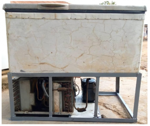
Figure 4. The developed cascade system
The machine's parts, including a compressor for HTC and LTC each, a condenser, two expansion valves, and an electrical fan motor, were acquired and linked to the copper pipes using bolts, nuts, rivets, welding, soldering, and riveting as needed for a unitary mechanism. The machine was filled with the appropriate working fluid (R410A and R404A, respectively, for HTC and LTC's respective refrigerants), and it was then linked to an electrical supply for a test run. While testing the system to determine its coefficient of performance, pressure and temperature detectors (gauges and digital thermocouples) were mounted at each compressor's intake and output, condenser, and evaporator for quantification of the corresponding pressure and temperature for computation. The fabricated cascade system is presented in Figure 4.
3.1 Protein concentration analysis
Under controlled temperature storage, the protein concentration in the fresh and frozen plasma was analysed before and after freezing in temperature ranges between -35℃ and -18℃. The results are displayed in Table 3.
Table 3. Plasma proteins concentrations
|
Plasma Proteins |
Before Freezing (g) |
After Freezing (g) |
|
Albumins |
10 |
10 |
|
Globulins |
0.75 |
0.74 |
|
Fibrinogen |
0.6 |
0.6 |
The protein concentration of albumins, globulins, and fibrinogen was found to be 10 g, 0.75 g, and 0.6 g per 250 ml, respectively, prior to freezing. While the same amount and nearly identical quality of plasma proteins were obtained after 140 minutes of freezing and 72 hours of storage in a temperature-controlled refrigerator, following tests, the samples that were maintained contained 10 g of albumin, 0.74 g of globulins, and 0.6 g of fibrinogen per bag. This suggests that plasma integrity and viability for safe transfusion are well regulated on a quantitative and qualitative level. However, service stress could be responsible for the negligible 0.01 g loss of globulin [17].
3.2 Design analysis of vapour-compression refrigeration cycle
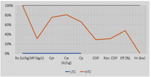
The results from the design analysis at varying operating conditions of the system using dissimilar refrigerants R410A and R404A are as presented in Table 4, which shows the comparison between the design performance analysis of a two-stage cascade refrigeration system whereby the system in both cycles is 75.25% (HTC) and 67.7% (LTC). The LT cycle had 59.4 kJ/kg compressor work done whereas, the HT cycle has 14.46 kJ/kg lower. The system refrigerating effect stands at 180.7 kJ/kg while the mass flow rate was lower at LT (0.00719 kg/s) than HT has 0.0156 kg/s. The cycle coefficient of performance for LTC and HTC are 3.04 and 7.66 respectively.
Table 4. Results of the various design and performance analysis of VCRS
|
System Parameters |
LTC |
HTC |
|
Refrigerating Effect (kJ/kg) |
180.7 |
- |
|
Mass Flow Rate (kg/s) |
0.00719 |
0.0156 |
|
Compressor Pressure Ratio |
6.1990 |
2.0689 |
|
Work Done by Compressor (kJ/kg) |
59.4 |
14.46 |
|
Compressor Power (kw) |
0.427 |
0.226 |
|
Cycle COP |
3.04 |
7.66 |
|
Revered Cycle COP |
4.49 |
10.18 |
|
System Efficiency (%) |
67.7 |
75.25 |
|
Heat Rejection (kw) |
- |
1.73 |
Figure 5 shows the relationship between the design parameters and performance analysis at various stages of low temperature and high temperature circuits. The graph shows that the refrigerating effect only takes place at the LTC while the mass flow rate is higher at HTC than LTC. On comparison, the compressor pressure ratios and work done by the system is high at the LTC than HTC. In case of system efficiencies, HTC has 75.25% while LTC has 67.7%. It implies that the design system meets the designed purpose.
Figure 5. System design analysis between LTC and HTC
3.3 COP of the developed cascade system ($\mathrm{COP}_{\mathrm{cas}}$)
The COP of the entire system, denoted as COPcas, is determined as outlined in Eq. (46).
$C O P_{cas}=\frac{R_e}{W_{C L}+W_{C H}}$ (46)
$\mathrm{COP}_{\mathrm{cas}}=2.45$ (47)
A coefficient of performance of 2.45 indicates that for every kilowatt of power consumed by the system's compressor (input power), 3 kilowatts of air-cooling power is attained. This falls within the typical range of COP for heat pump systems, which generally ranges from 2 to 4.5. It's commonly understood that the CoP of a cascaded device declines as the temperature in the refrigerated space decreases [18].
Isentropic efficiency, $\eta_{\text {isentropic}}$. The isentropic efficiency of the system is estimated by Eq. (48):
$\eta_{ {isentropic }}=\frac{W_{\text {rev }}}{W_{\text {actual }}} \times 100 \%$ (48)
$\eta_{\text {isentropic }}=58.5 \%$ (49)
3.4 The influence of temperature difference on cascade condenser performance
Table 5 illustrates the temperature variance within the cascade condenser $(\Delta \mathrm{TCC})$, ranging from 6 to 2 degrees Celsius in 1-degree increments, while maintaining constant values for other parameters. Figure 6 illustrates the impact of varying the temperature difference within the cascade condenser on the system’s refrigerating effect, performance coefficient, and isentropic efficiency [19]. It shows how reducing the temperature difference $(\Delta \mathrm{TCC})$ in the cascade condenser from 6℃ to 2℃ in 1℃ steps affect these parameters; the refrigerating effect escalates from 172.3 to 179.6 kJ/kg. Similarly, the isentropic efficiency shows an increase from 41.79% to 42.29% under the same conditions.
Table 5. Effect of variation in temperature difference in cascade condenser
|
TEL (℃) |
PSL (MPa) |
TDL (℃) |
PDL (MPa) |
TCL (℃) |
THE (℃) |
PS MPa |
TH ℃ |
PDH (Ma) |
TH (℃) |
$\Delta$ TCC |
|
-35 |
0.23 |
39 |
1.58 |
23 |
12 |
0.88 |
59 |
1.69 |
40 |
6 |
|
-35 |
0.23 |
38 |
1.56 |
22 |
12 |
0.90 |
60 |
1.69 |
40 |
5 |
|
-35 |
0.22 |
37 |
1.49 |
21 |
12 |
0.93 |
62 |
1.69 |
40 |
4 |
|
-35 |
0.22 |
36 |
1.45 |
20 |
12 |
0.95 |
64 |
1.69 |
40 |
3 |
|
-35 |
0.22 |
35 |
1.42 |
19 |
12 |
0.97 |
65 |
1.69 |
40 |
2 |
Figure 6. Variation in temperature difference in cascade condenser on Re and efficiency
3.5 Storage time against fresh frozen plasma quality
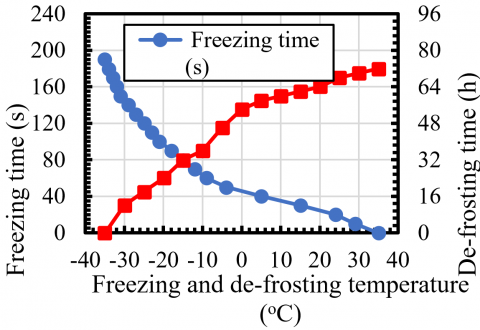
Figure 7 illustrates the freezing rate of fresh plasma and the impact of temperature on the change in frozen plasma over time. The system maintained the nutritional integrity of the plasma for a period of 24 hours within a controlled-temperature storage facility, where the temperature was maintained at a level 20℃ below the storage recommendation provided by the WHO [20]. Upon thawing at -5℃, the plasma retained its constituents for a duration of 48 hours. By keeping the plasma at a temperature of 35℃, the device preserved the plasma proteins in their original state for 72 hours, demonstrating its suitability for plasma management tasks such as rapid freezing, storage, and distribution of other temperature-sensitive medications and vaccines under controlled conditions. It is evident that one of the advantages of cascade refrigeration systems lies in their capability to safeguard fresh biological materials, food products, medications, and blood components. Another advantage is the energy efficiency of the system, making it suitable for commercial applications in both developed and developing countries [21, 22].
Figure 7. Freezing and de-frosting plasma time against temperature
The nutritional status and biological activities of the collected plasma were found to be the same as 0.017/0.011, 33.2/40.1, 83.5/80.2, 3.10, and 34.7 g/dL for pre-albumin, albumin, protein, fibrinogen, and globulin, respectively. The results of the system performance analysis showed 180.20 kJ/kg cooling effect and 3.6 coefficient of performance. In contrast to other technologies, the experimental machine freezes quickly effectively managed heat-sensitive medications and uses less energy by saving 3942 MJ [7-9].
An effective model technology that can address issues related to stable, long-term, and extremely low-temperature applications is the cascade refrigeration system. The work offered the fundamental requirements for design, energy-efficient formulations, operation, deep freezing, and sustaining stability at extremely low temperatures. However, the paper came to the conclusion that a two-stage vapour compression refrigeration cycle should be designed for the efficient, quick, and homogeneous freezing of fresh blood plasma at temperatures between 35 and -35 degrees Celsius while maintaining both its quality and quantity. The fresh frozen plasma is kept at -35℃ in refrigerated space by a heat-sensitive, temperature-controlled storage unit, increasing its shelf life for medicinal uses. The decision to use the refrigerants R410A and R404A as working fluids was unavoidable in order to quickly reach the necessary temperature of -35℃. By addressing urgent demands, particularly those related to casualties, ensuring the safety of lives during transfusion medicine, and regulating heat-sensitive medications for effective product delivery in countries with hot climates, this technology is set to improve health care on many different levels. For efficient service delivery, the system should be integrated at every health facility or donation camp. It has the potential to be commercially reproduced.
Challenge: Obtaining free human blood donors for a repeated experiment proved unethical and uncomfortable.
[1] Rabbani, M., Karma, N., Patil, N., Wankhade, A. and Deshmukh, R. (2017). Cascade refrigeration system ‘For Blood Storage’. International Journal of Innovative Science and Research Technology, 2(6): 20-23.
[2] Bolaji, B.O., Huan, Z. (2014). Performance investigation of some hydro-fluorocarbon refrigerants with low global warming as substitutes to R134a in refrigeration systems. Journal of Engineering Thermophysics, 23(2): 148-157. https://doi.org/10.1134/S1810232814020076
[3] Bolaji, B.O. (2014). Theoretical analysis of the energy performance of three low global warming potential hydro-fluorocarbon refrigerants as R134a alternatives in refrigeration systems. Proceedings of the Institution of Mechanical Engineers, Part A: Journal of Power and Energy, 228(1): 56-63. https://doi.org/10.1177/0957650913507252
[4] Syaka, D.R., Sugita, I.W., Bijaksana, M. (2019). Characteristics study of two-stage cascade refrigeration system design for household air blast freezing. International Journal of Mechanical Engineering and Technology (IJMET), 10(1): 1804-1813.
[5] Tu, Y.F., Chien, C.S., Yarmishyn, A.A., Lin, Y.Y., Luo, Y.H., Lin, Y.T., Lai, W.Y., Yang, D.M., Chou, S.J., Yang, Y.P., Wang, M.L., Chiou, S.H. (2020). A review of SARS-CoV-2 and the ongoing clinical trials. International Journal of Molecular Sciences, 21(7): 2657. https://doi.org/10.3390/ijms21072657
[6] Mouneer, T.A., Elshaer, A.M., Aly, M.H. (2021). Novel cascade refrigeration cycle for cold supply chain of COVID-19 vaccines at ultra-low temperature-80℃ using ethane (R170) based hydrocarbon pair. World Journal of Engineering and Technology, 9(2): 309-336. https://doi.org/10.4236/wjet.2021.92022
[7] Subramani, N., Prakash, M.J. (2011). Experimental studies on a vapour compression system using nanorefrigerants. International Journal of Engineering, Science and Technology, 3(9): 95-102. https://doi.org/10.4314/ijest.v3i9.8
[8] Bolaji, B.O. (2014). Theoretical analysis of the energy performance of three low global warming potential hydro-fluorocarbon refrigerants as R134a alternatives in refrigeration systems. Journal of Power and Energy, 228(1). https://doi.org/10.1177/0957650913507252
[9] Pannusamy, S., Gangadharan, S., Kalaiarasu, B. (2022). An exergy analyysis for overall hidden losses of energy in solar water heater. Thermal Science, 26: 343. https://doi.org/10.2298/TSCI200530343P
[10] Selvnes, H., Allouche, Y., Manescu, R.I., Hafner, A. (2021). Review on cold thermal energy storage applied to refrigeration systems using phase change materials. Thermal Science and Engineering Progress, 22: 100807. https://doi.org/10.1016/j.tsep.2020.100807
[11] Ratio, C. (2018). Single Stage, Compound, Cascade and Booster Systems and Inter-Stage Cooling Methods, pp. 11-18.
[12] Dharmadhikari, S. (1997). Consider trigeneration techniques for process plants. Hydrocarbon Processing, 76(7).
[13] Bolaji, B.O., Huan, Z., Borokinni, F.O. (2014). Energy performance of eco-friendly R152a and R600a refrigerants as alternative to R134a in vapour compression refrigeration system. Analele Universitatii'Eftimie Murgu', 21(1): 354.
[14] Zhang, N. (2023). Enhanced estimation of thermodynamic parameters: A hybrid approach integrating rough set theory and deep learning. International Journal of Heat and Technology, 41(6): 1587-1595. https://doi.org/10.18280/ijht.410621
[15] Vaisman, I.B. (1998). Computational comparison of R22 and R407C air conditioners with rotary vane compressors. The International Refrigeration and Air Conditioning Conference.
[16] Martins, L.N., Fábrega, F.M., d’Angelo, J.V.H. (2012). Thermodynamic performance investigation of a trigeneration cycle considering the influence of operational variables. Procedia Engineering, 42: 1879-1888. https://doi.org/10.1016/j.proeng.2012.07.584
[17] Jiang, B.H., Gao, Z.J., Lung, C.Y. et al. (2024). Enhancing the efficiency of indoor perovskite solar cells through surface defect passivation with coplanar Heteroacene cored A–D–A-type molecules. Adyanced Functional Materials, 34(19): 2312819. https://doi.org/10.1002/adfm.202312819
[18] Wang, L., Chang, L., Huo, R., Lu, X., Yang, Y. (2024). Application of machine learning in thermodynamic system modelling and optimization. International Journal of Heat and Technology, 42(5): 1613-1621. https://doi.org/10.18280/ijht.420515
[19] Abdulghafor, I.A., Ali, S.A., Kadhim, S.A., Al-Mrayattee, H.M., Hammoodi, K.A. (2024). Exergy analysis of a solar heating system in indoor spaces. International Journal of Heat and Technology, 42(5): 1551-1558. https://doi.org/10.18280/ijht.420508
[20] Prommas, R., Phiraphat, S., Rattananadecho, P. (2019). Energy and exergy analyses of PV roof solar collector. International Journal of Heat and Technology, 37(1): 303-312. https://doi.org/10.18280/ijht.370136
[21] Fan, B., Jin, X., Fang, X., Du, Z. (2014). The method of evaluating operation performance of HVAC system based on exergy analysis. Energy and Buildings, 77: 332-342. https://doi.org/10.1016/j.enbuild.2014.03.059
[22] Kazanci, O.B., Shukuya, M., Olesen, B.W. (2016). Exergy performance of different space heating systems: A theoretical study. Building and Environment, 99: 119-129. https://doi.org/10.1016/j.buildenv.2016.01.025