Shuang Wang* | Xiaohui Chang | Liguo Wang | Lei Zhang | Manshuai Wang | Jiahui Wang
© 2024 The authors. This article is published by IIETA and is licensed under the CC BY 4.0 license (http://creativecommons.org/licenses/by/4.0/).
OPEN ACCESS
As the proportion of renewable energy in power systems continues to increase, the frequency stability of the power grid faces unprecedented challenges. Synchronous condensers, as key devices for frequency regulation and load balancing, directly influence the operational safety and stability of the power grid. However, existing research primarily focuses on the electrical performance analysis of synchronous condensers, with limited attention paid to their thermodynamic performance, particularly the impact of temperature fields on equipment losses and frequency stability. The internal temperature variations in synchronous condensers not only affect the loss levels but also alter the electrical characteristics of the equipment, thereby significantly impacting the grid's frequency regulation. Therefore, studying the thermodynamic performance of synchronous condensers and its effect on grid frequency stability is of great theoretical and practical importance. Current domestic and international research on synchronous condensers mainly focuses on electromagnetic field analysis and dynamic characteristics, with limited exploration of thermodynamic properties and temperature effects. Most existing methods neglect the comprehensive impact of temperature on synchronous condenser performance, leading to insufficient understanding of its behavior and stability in real-world operations. In particular, under complex grid operating conditions, traditional methods struggle to fully consider the potential impact of temperature field variations on frequency stability. Hence, in-depth research on the thermal effects of synchronous condensers and their role in grid frequency stability has become a key solution to this problem. This paper, based on the thermodynamic performance of synchronous condensers, investigates their impact on power grid frequency stability. The specific research includes loss calculations of synchronous condensers, two-dimensional electromagnetic field simulations considering material temperature effects, and the development of computational fluid dynamics (CFD) models for temperature field simulations. Through these studies, the paper aims to provide theoretical support for optimizing the design and regulation strategies of synchronous condensers and offer new ideas and methods for improving power grid frequency stability.
synchronous condenser, thermodynamic performance, power grid frequency stability, loss calculation, electromagnetic field simulation, temperature field simulation
With the ongoing transformation of the global energy structure, the stability and reliability of power systems are facing increasing challenges [1-4]. Especially in the context of the rising share of renewable energy, the issue of grid frequency fluctuations has become more prominent. Frequency fluctuations not only directly affect the stable operation of the grid but also may lead to equipment damage and power supply interruptions [5-7]. Therefore, improving the frequency stability of the grid has become one of the key research areas in power systems. Synchronous condensers, as key electrical devices, play a crucial role in regulating grid frequency, balancing loads, and providing reactive power [8-10]. However, the impact of changes in thermodynamic performance on their operating status and frequency stability has not been fully studied and explored.
Regarding the relationship between grid frequency stability and synchronous condensers, related research mainly focuses on the electrical performance and dynamic characteristics analysis of synchronous condensers, with relatively little consideration of their thermodynamic properties and temperature effects. The operating status of synchronous condensers is influenced not only by electrical parameters but also by the internal temperature field changes [11-14]. Fluctuations in the temperature field will lead to increased losses in synchronous condensers, thus affecting the equipment's stability and its ability to regulate grid frequency. Therefore, in-depth research on the thermodynamic performance of synchronous condensers and its impact on grid frequency stability is of significant theoretical and practical importance.
Existing research methods mostly focus on the electromagnetic performance analysis and dynamic response studies of synchronous condensers, neglecting the comprehensive impact of thermal effects on their performance [15-20]. Especially in complex grid environments, traditional research methods often fail to fully consider temperature field variations and the thermodynamic properties of materials [21-23]. These deficiencies in research methods lead to a lack of a systematic understanding of the thermodynamic performance of synchronous condensers and their specific impact on grid frequency stability, which in turn affects the development of optimization designs and operational strategies for condensers.
This paper's research will start from the thermodynamic performance of synchronous condensers, systematically analyzing its impact on grid frequency stability. The specific research contents include: first, conducting loss calculations of synchronous condensers, analyzing energy losses under different operating conditions; second, considering material temperature effects, performing two-dimensional electromagnetic field simulations of synchronous condensers, and studying the impact of temperature changes on the equipment's performance; third, constructing a CFD model for the temperature field simulation of synchronous condensers, deeply analyzing the role of temperature distribution in regulating grid frequency stability. Through the above studies, the aim is to provide more accurate regulation schemes for grid frequency stability and offer theoretical foundations and technical support for the design and optimization of synchronous condensers.
Synchronous condensers play a core role in regulating frequency and balancing loads in power systems, and their operating status is crucial to the frequency stability of the grid. In actual operation, changes in temperature directly affect the heating characteristics and energy losses of synchronous condensers. As temperature increases, the electrical losses of the equipment exhibit different patterns of change, especially under heavy load or in complex operating environments, where thermal effects have a significant impact on the electromagnetic performance of the equipment. Therefore, this paper systematically studies the impact of temperature on the heating of synchronous condensers, using finite element electromagnetic simulation methods to calculate the thermal losses under different temperatures. The loss data will be presented in the form of curves to better understand the specific impact of temperature on equipment heating and losses and to provide data support and theoretical foundations for further studying the role of synchronous condenser thermodynamic performance in grid frequency stability.
In the operation of synchronous condensers, the core is one of the main components where electromagnetic energy is converted into thermal energy. As temperature increases, the electrical conductivity and magnetic properties of the core material change, which directly affects the calculation of core losses. Specifically, with rising temperature, the hysteresis losses of the core will increase, and eddy current losses will also rise, as high temperatures lower the resistivity of the core material, enhancing the generation of eddy currents. Therefore, when calculating the thermal losses of synchronous condensers, it is necessary to consider the impact of temperature on the magnetic characteristics and conductivity of the core material to accurately estimate the core losses at different temperatures. Specifically, assuming the core losses are represented by ODr, hysteresis losses, classical eddy current losses, and anomalous eddy current losses are represented by Og, Oz, Or, respectively, the magnetic flux density amplitude is represented by Yl, and the frequency is represented by d. The relationship between the hysteresis loss coefficient, classical eddy current loss coefficient, and anomalous eddy current loss coefficient is Jg>Jz>Jr, and the hysteresis loss index is represented by x. The calculation formula is as follows:
${{O}_{Dr}}={{O}_{g}}+{{O}_{z}}+{{O}_{r}}={{J}_{g}}dY_{l}^{\beta }+{{J}_{z}}{{d}^{2}}Y_{l}^{2}+{{J}_{r}}{{d}^{1.5}}Y_{l}^{1.5}$ (1)
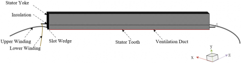
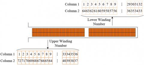
Copper loss is primarily caused by the Joule heat generated when current flows through the copper windings, and its magnitude is proportional to the current strength and resistance. The resistance of the copper windings increases with rising temperature, which means that, for the same current, copper losses will rise significantly at high temperatures. Therefore, when calculating copper loss, the impact of temperature on the resistance of the copper windings must be considered. The temperature coefficient of resistance for copper is known and describes the effect of temperature changes on resistance. Typically, the resistance value of copper at standard temperature can be corrected using the temperature coefficient. In the process of thermal loss calculation, the resistance value of the copper windings at different temperatures needs to be first calculated, then combined with the current intensity, and the thermal loss in the copper windings is determined using Joule’s law. Figure 1 shows the copper loss calculation model. Figure 2 shows a schematic of the winding numbering. Assuming the number of winding phases of the synchronous condenser is represented by l, the effective current of the winding phase is represented by U, and the effective resistance value of each winding phase is represented by E, the calculation formula is:
$O_{Z_i}=l U^2 E$ (2)
Figure 1. Copper loss calculation model
Figure 2. Schematic of winding numbering
Eddy current loss is another major form of thermal loss in synchronous condensers, particularly in high-frequency electromagnetic environments, where eddy current loss is especially significant. Eddy current loss is primarily caused by the variation of alternating magnetic fields in conductors, which induces currents to flow within the conductor, and these eddy currents generate heat. The metal parts of synchronous condensers may all be affected by eddy current effects under changing magnetic fields. As the temperature rises, it not only alters the electrical conductivity of the metal material but may also change its magnetic permeability, thereby affecting the magnitude of eddy current losses. Especially at the interface between copper windings and the core, temperature changes can lead to significant variations in eddy current losses. The calculation of eddy current losses usually requires consideration of material conductivity, magnetic permeability, and the frequency characteristics of the electromagnetic field. Assuming the amplitude of current density in the metal parts of the synchronous condenser is represented by K, and the conductivity of the permanent magnet is represented by δ, the calculation formula is:
$O_{r} = {∰\frac{|K|^{2}}{2\delta}}dn$ (3)
The rotor of the synchronous condenser is also affected by mechanical losses during its rotation. Mechanical losses mainly come from friction between the rotor and stator, wind resistance, bearing friction, and other factors. These mechanical losses convert into heat during operation, leading to an increase in temperature. The relationship between mechanical loss and temperature is more complex, as rising temperature may affect the performance of lubricants, increase the friction coefficient, and thus lead to an increase in mechanical losses. When the rotor of the synchronous condenser rotates at high speed, changes in airflow will also cause wind resistance losses. Wind resistance losses are influenced by temperature changes, as factors like fluid viscosity and air density are affected. In thermal loss calculation, it is usually necessary to establish a dynamic model based on the specific structure of the synchronous condenser, combining factors such as rotor speed, bearing type, and other mechanical factors to calculate the thermal energy from mechanical losses. Assuming the surface roughness of the rotor core is represented by c, the friction coefficient by Zd, the surrounding gas density by ϑ0, the angular velocity of rotor rotation by μl, the radius of the rotor by e, and the axial length of the rotor by M, the calculation formula is:
${{O}_{d}}=c{{Z}_{d}}{{\vartheta }_{0}}\tau \mu _{l}^{3}{{e}^{4}}M$ (4)
In addition to core losses, copper losses, eddy current losses, and mechanical losses, synchronous condensers also experience certain additional losses. Additional losses include energy losses caused by other factors in the system, such as losses in electrical insulation materials, electrical contact issues caused by temperature, and other non-ideal factors. As the temperature increases, the performance of electrical insulation materials may degrade, leading to an increase in their losses. For example, the electrical properties of insulation materials are affected at high temperatures, resulting in increased leakage currents and additional losses. Furthermore, higher temperatures may cause poor electrical contacts, increasing the formation of localized hotspots, which further exacerbate additional losses. In thermal loss calculations, the impact of additional losses is usually more complex and cannot be accurately calculated by simple physical models. Therefore, supplementary estimation through practical tests and empirical data is required. The impact of temperature on additional losses needs to be considered in conjunction with the actual operating environment and material characteristics of the synchronous condenser, in order to conduct a detailed thermal loss analysis and provide more comprehensive support for the subsequent temperature characteristic study.
Temperature changes lead to changes in the electrical properties of materials inside the synchronous condenser, thus affecting its electromagnetic performance. Especially, copper windings, as important conductive materials, have temperature characteristics closely related to their current conduction performance. An increase in temperature may cause the resistance of the copper windings to increase, leading to greater energy losses and further affecting the overall efficiency and frequency regulation ability of the synchronous condenser. By adopting a two-dimensional electromagnetic field simulation that considers temperature effects, the variation of the copper windings and overall electromagnetic performance of the synchronous condenser under different temperature conditions can be deeply explored.
In the electromagnetic field simulation of the synchronous condenser, in order to simplify the problem and make the calculation feasible, it is assumed that the current density and vector magnetic potential only have axial components. In other words, it is assumed that the main variation direction of the current and magnetic field is along the axial direction, and changes in the radial direction are neglected, transforming the problem into an electromagnetic field problem in a two-dimensional planar domain. This assumption can well approximate the electromagnetic field distribution in most practical applications, especially in rotating machinery like synchronous condensers. To consider the temperature effect, we need to introduce the impact of temperature on the electrical properties of materials. Temperature changes not only cause variations in material resistance and magnetic permeability but also affect the material's thermal expansion properties, which in turn change the electromagnetic field distribution and energy losses. Furthermore, during the operation of the synchronous condenser, the resistance and electromagnetic performance of the copper windings are very sensitive to temperature changes. As the temperature increases, the resistance of the copper windings increases, leading to a decrease in current conduction performance, thereby causing greater thermal losses. In addition, temperature changes also affect the electrical performance of the copper windings, such as inductance and induced electromotive force. Considering these factors, the two-dimensional electromagnetic field simulation must not only simulate the conventional electromagnetic field distribution but also comprehensively consider the impact of temperature effects on electrical properties. The specific assumptions are that the parallel plane domain perpendicular to the synchronous condenser axis is represented by Ψ, magnetic permeability by ω, vector magnetic potential by X, electrical conductivity by δ, source current density by Kt, the first-type boundary condition by Π1, the second-type boundary condition by Π2, and the coercivity of the permanent magnet by Gs. The electromagnetic field problem in the parallel plane domain of the synchronous condenser can be characterized by the following equation:
$\left\{ \begin{align} & \Psi :\frac{\partial }{\partial a}\left( \frac{1}{\omega }\frac{\partial X}{\partial a} \right)+\frac{\partial }{\partial b}\left( \frac{1}{\omega }\frac{\partial X}{\partial b} \right)=\delta \frac{\partial X}{\partial s}-{{K}_{t}} \\ & {{\Pi }_{1}}:X={{X}_{0}},{{\Pi }_{2}}:\frac{1}{\omega }\frac{\partial X}{\partial v}=-{{G}_{s}} \\\end{align} \right.$ (5)
(1) Temperature characteristics of copper windings and resistance variation
The resistance of the copper winding in the synchronous condenser changes with temperature, and the impact of temperature on its resistance is significant. According to the relationship between resistivity and temperature, the resistance value Rt of the copper winding can be corrected using the following formula: Rt=R20[1+α(t-20)]. Here, R20 is the resistance value of the winding at 20℃, α is the temperature coefficient of the copper conductor, and t is the temperature. The formula indicates that as the temperature increases, the resistance of the copper winding increases linearly, with the increase being proportional to the change in temperature. As the temperature rises, the increase in resistance of the copper winding leads to an increase in thermal losses due to current flowing through the winding, thereby affecting the electromagnetic characteristics of the synchronous condenser.
Temperature changes have a direct impact on the resistance losses of the copper windings in the synchronous condenser. As the resistance of the copper windings changes with temperature, the resistance increases with rising temperature, leading to greater Joule heating losses. When conducting a two-dimensional electromagnetic field simulation considering temperature effects, it is essential to incorporate the temperature dependence of resistance into the model to accurately calculate the current conduction characteristics and losses at different temperatures. Through simulation analysis, the impact of changes in copper winding resistance with temperature on the current flow path can be quantified, and the energy losses under different operating conditions can be predicted. In addition, the increase in resistance in a high-temperature environment may also lead to the formation of local hotspots, further exacerbating losses and affecting the stability of the synchronous condenser.
(2) Temperature dependence of overall electromagnetic performance of synchronous condenser
The overall electromagnetic performance of the synchronous condenser is not only influenced by the changes in copper winding resistance but also closely related to the temperature characteristics of other materials and structures within the synchronous condenser. When performing a two-dimensional electromagnetic field simulation considering material temperature effects, it is necessary to simultaneously consider the temperature dependence of conductors, core materials, and insulation materials. For example, the magnetic permeability of core materials typically decreases with temperature, which will lead to changes in the magnetic field distribution and magnetic flux density, thereby affecting the power transmission efficiency of the synchronous condenser. As the temperature rises, the electrical insulation of insulation materials also decreases, which may lead to problems such as current leakage or winding short circuits.
As the operating temperature of the synchronous condenser increases, its electromagnetic losses will significantly increase, mainly reflected in resistance losses, hysteresis losses, and eddy current losses. The resistance of the copper windings increases with temperature, leading to more Joule heating losses. Additionally, the hysteresis and eddy current losses of the core material also worsen with increasing temperature, as the magnetic permeability of the core decreases at high temperatures, causing more intense magnetic flux changes and thereby increasing the losses. The two-dimensional electromagnetic field simulation needs to consider not only the electromagnetic properties of the copper windings and core materials but also the changes in their physical properties with temperature variations to accurately simulate the losses under different temperatures. Assume the residual flux density at s0℃ is represented by Yes0, the temperature coefficient by xYe, the irreversible loss rate by UM, the operating temperature by t1s1, and the calculated coercivity at s0℃ by Ges0. The residual flux density at s1℃ is represented by Yes1, and the coercivity at s1℃ by Ges1. The temperature effect on the overall electromagnetic performance of the synchronous condenser can be expressed as:
$\begin{align} & {{Y}_{e{{s}_{1}}}}={{Y}_{e{{s}_{0}}}}\left( 1-\frac{{{U}_{M}}}{100} \right)\left[ 1+\left( {{s}_{1}}-{{s}_{0}} \right)\frac{{{\beta }_{{{Y}_{e}}}}}{100} \right] \\ & {{G}_{e{{s}_{1}}}}={{G}_{e{{s}_{0}}}}\left( 1-\frac{{{U}_{M}}}{100} \right)\left[ 1+\left( {{s}_{1}}-{{s}_{0}} \right)\frac{{{\beta }_{{{Y}_{e}}}}}{100} \right] \\\end{align}$ (6)
From the above temperature characteristic analysis, it is known that during the operation of the synchronous condenser, copper losses are mainly influenced by the winding resistance and the current passing through the windings. According to the known copper loss formula, when the current remains constant, copper loss shows a positive correlation with the winding temperature. This is because as the temperature increases, the resistance of the copper windings increases, causing more electrical energy to be converted into heat energy, thus increasing copper losses. By using interpolation in finite element simulations, copper losses can be expressed as a function of winding temperature, further providing a basis for the quantitative analysis of the temperature effect on copper losses. Under different operating conditions of the synchronous condenser, especially at high speeds and under high load conditions, the copper winding temperature may increase significantly, which directly affects the system’s thermal management and efficiency.
Iron losses in the synchronous condenser are mainly caused by changes in the magnetic flux density of the stator and rotor cores, and the impact of temperature variations on these losses is more complex. According to the formula, iron losses are closely related to the stator current and the magnetic field of the permanent magnets. Since the stator current and operating frequency remain constant under certain operating conditions, the change in core magnetic flux density is mainly influenced by the temperature variation of the permanent magnet. When the temperature of the permanent magnet rises, its residual flux density decreases, leading to a reduction in the magnetic flux density of the stator and rotor cores, which results in a decrease in iron losses of the core with the increase in the permanent magnet temperature. However, in the synchronous condenser, the rotor iron losses are small and can be neglected, with the primary focus on stator iron losses. Therefore, by using interpolation to express stator iron losses as a function of permanent magnet temperature, the changes in iron losses under different temperature conditions can be accurately simulated.
The thermodynamic performance of the synchronous condenser is closely related to the distribution of its internal temperature field. Especially under high load operation, uneven temperature distribution can lead to local overheating of the equipment, thereby affecting its stability and service life. To more accurately simulate the temperature field of the synchronous condenser under different operating conditions, this paper uses Star-CCM+ software to establish a CFD simulation model for the temperature field of the synchronous condenser.
In the process of constructing the CFD simulation model for the synchronous condenser, the first step is to perform geometric modeling, which involves creating a 3D model of the synchronous condenser. This includes the stator, rotor, winding ends, rotor end faces, and other key structural components. Once the geometric modeling is completed, grid meshing is required to ensure the accuracy and computational efficiency of the simulation results. In Star-CCM+, triangular elements are used for the surface mesh, while polyhedral meshes and embedded thin body meshes are selected for the volume mesh to ensure sufficient resolution in detailed areas. Specifically, at the contact surfaces with critical areas such as the air gap, winding ends, and rotor end faces, the mesh density needs to be sufficiently high to accurately capture the details of heat conduction and heat convection. To ensure the precise simulation of the heat transfer process, the wall mesh of the fluid domain should satisfy at least three boundary layers, which can better capture the changes in the fluid boundary layer. Ultimately, the total number of volume mesh elements in the entire solution domain is approximately 11 million, which ensures a balance between simulation accuracy and computational load. Through this meshing method, the CFD simulation can accurately simulate the temperature field variation of the synchronous condenser under different operating conditions, especially in the complex heat conduction process between the rotor and stator. It is assumed that the temperature of the synchronous condenser system is represented by S, the thermal conductivity coefficients of various materials along the a, b, and c directions in the solution domain are represented by Ja, Jb, and Jc, respectively, the sum of the volume density of each heat source in the solution domain is represented by w, the specific heat capacity is represented by z, the density is represented by ε, time is represented by π, the adiabatic boundary surface is represented by T1, the heat dissipation boundary surface is represented by T2, the temperature of the medium around the heat dissipation surface T2 is represented by S2, and the heat dissipation coefficient of the heat dissipation surface T2 is represented by β, and the normal heat conduction coefficient for T1 > T2 is represented by J. According to heat transfer theory, the three-dimensional heat conduction equation for the synchronous condenser is:
$\left\{ \begin{align} & {{J}_{a}}\frac{{{\partial }^{2}}S}{\partial {{a}^{2}}}+{{J}_{b}}\frac{{{\partial }^{2}}S}{\partial {{b}^{2}}}+{{J}_{c}}\frac{{{\partial }^{2}}S}{\partial {{c}^{2}}}+w=z\varepsilon \frac{\partial S}{\partial \pi } \\ & -J{{\left. \frac{\partial S}{\partial v} \right|}_{{{T}_{1}}}}=0,-J{{\left. \frac{\partial S}{\partial v} \right|}_{{{T}_{2}}}}=\beta \left( S-{{S}_{2}} \right) \\\end{align} \right.$ (7)
Regarding the boundary condition settings for the simulation model, considering the operating environment and heat dissipation mechanism of the synchronous condenser, convective heat transfer boundary conditions are applied between the stator coil ends and the rotor end faces with air. Specifically, an equivalent convective heat transfer coefficient is used to simplify the modeling process, and the equivalent heat dissipation coefficient grq of the winding ends is calculated using empirical formulas. Since this model does not consider the flow of internal air, the heat transfer in the air gap is equivalently modeled through the contact thermal resistance between the stator and rotor, using the equivalent thermal resistance eGA of the air gap to describe its thermal resistance characteristics. This simplification helps reduce computational complexity while still maintaining the rationality of the thermodynamic process. The outer shell of the synchronous condenser is equipped with a water-cooling system, so heat transfer between the shell and air can be neglected. With the support of these boundary conditions, the heat conduction equation can accurately describe the heat flux distribution within the synchronous condenser, especially in areas such as the winding ends, rotor end faces, and air gap regions. Using these boundary conditions and the heat conduction equation, the resulting temperature field can provide a theoretical basis for further analyzing the thermal management performance and heat dissipation capacity of the synchronous condenser under different operating conditions. It is assumed that the Nusselt number at the winding end is represented by Nuirq, the Reynolds number of the airflow at the winding end surface is represented by Rerq, the outer radius of the stator is represented by E1, the inner radius of the stator is represented by Ev1, the outer radius of the rotor is represented by E2, the air kinematic viscosity is represented by n, the air thermal conductivity is represented by ηKQ, and the calculation formula for grq is:
$\begin{align} & {{g}_{rq}}=\text{N}{{\text{u}}_{rq}}{{\eta }_{KQ}}/\left( {{E}_{1}}+{{E}_{v1}} \right) \\& V{{i}_{rq}}=0.456\operatorname{Re}_{rq}^{0.6},\operatorname{Re}=\left( {{E}_{1}}+{{E}_{v1}} \right)/n\times 2\tau {{E}_{2}}{{v}_{1}}/60 \\\end{align}$ (8)
Assume that the empirical coefficient is represented by ρ, the Reynolds number of the air gap is represented by ErGA, the air gap thickness is represented by σ, and the calculation formula for eGA is:
${{e}_{GA}}=\rho {{\left( \sigma /{{E}_{2}} \right)}^{-0.25}}\text{R}{{\text{e}}^{-0.5}}\sigma /{{\eta }_{KQ}},\text{R}{{\text{e}}_{GA}}=2\tau {{E}_{2}}\sigma /60n$ (9)
In the process of constructing the CFD simulation model for the temperature field of the synchronous condenser, the loss conditions of each component and heat source loading need to be clarified first. Based on the loss values under the operating conditions of 500 r/min and 500 Nm, these losses will be used as heat sources in the temperature field model to ensure that the simulation can accurately model the thermal behavior of the synchronous condenser under actual operating conditions. Specifically, the stator copper loss is 6530 W, which is applied as the main heat source in the model, while the winding ends have more significant temperature rise due to poor heat dissipation conditions. To further improve simulation accuracy, the initial temperature of the model is set to 20℃, representing the initial thermal state of the synchronous condenser under stationary or low-load conditions. The coolant used is water, with an inlet temperature also set to 20℃, and a flow rate of 8 L/min, simulating the cooling effect in actual operation. The simulation runtime is set to 1000 seconds to observe the temperature changes of the synchronous condenser over a short period. During the simulation, considering the temperature effects on the materials, the temperature-induced change in stator copper loss is 6%, but the overall change is relatively small, indicating that the impact of temperature effects on losses is relatively low under this operating condition.
Through the simulation calculation, the temperature field distribution of various components of the synchronous condenser under the conditions of 500 r/min and 500 Nm was obtained. The simulation results show that at low speeds, the main heat loss comes from the stator copper windings. The winding ends have a more significant temperature rise due to poor heat dissipation as they are in direct contact with air, with the highest temperature reaching 59.6℃. The temperature rise on the rotor side is lower due to the relatively low speed of the synchronous condenser, resulting in smaller rotor core losses and permanent magnet eddy current losses, so the temperature rise in the rotor portion is relatively small. Additionally, due to the presence of the coolant, the temperature rise in the stator core is also relatively stable, avoiding high temperature fluctuations. The simulation results show that the average temperature of the entire system is 28℃, while the average temperature of the windings is 36℃. These results reflect the temperature distribution of the synchronous condenser under low load and high cooling efficiency, particularly how the temperature variation at the winding ends has a significant impact on the overall thermal management.
The synchronous condenser plays a key role in regulating grid frequency stability, but its performance is significantly affected by temperature effects. This paper combines the control strategy of the synchronous condenser to analyze the impact of temperature on synchronous condenser losses and further explores its effect on grid frequency stability.
The thermodynamic performance of the synchronous condenser on grid frequency stability is a complex system effect that involves the interaction of electromagnetic performance, temperature characteristics, and energy losses. First, the temperature characteristics of the copper windings and the core directly affect the electromagnetic performance of the synchronous condenser. The resistance of the copper windings increases with temperature, leading to higher copper losses and more heat generation. The magnetic properties of the core also adjust with temperature variations. At high temperatures, the residual magnetism of the permanent magnets decreases, resulting in a reduction in magnetic flux density in the core, which decreases core losses. However, this temperature effect is nonlinear, and at high-speed operation or high load, the temperature rise of the copper windings may significantly increase copper losses and affect the conduction efficiency of the current. Furthermore, the effect of temperature on core losses is more complex, especially at high temperatures, where changes in core losses may affect the power output and thermal management requirements of the synchronous condenser. Therefore, the temperature-induced changes in losses not only affect the thermal balance of the synchronous condenser but also indirectly influence its ability to regulate grid frequency.
One of the main functions of the synchronous condenser is to regulate the grid frequency to maintain grid stability. At high loads or prolonged operation, due to the increase in temperature, the increase in copper losses and core losses may lead to a decrease in the efficiency of the synchronous condenser, thus affecting its power output capacity. The increase in the resistance of the copper windings converts more electrical energy into heat, which causes the temperature of the synchronous condenser to rise further. This exacerbates the difficulty in heat dissipation and may cause the synchronous condenser to overheat, ultimately affecting its regulation ability. Core losses decrease as the temperature of the permanent magnets rises, which reduces core losses to some extent, but may also lead to the degradation of permanent magnet performance, which in turn affects the precision of the synchronous condenser's power regulation. Since the temperature effect on synchronous condenser losses is nonlinear, it is necessary to monitor and adjust the operational state of the synchronous condenser in real-time to ensure its stable operation under high temperature conditions and maintain grid frequency stability.
In the operation of the synchronous condenser, the impact of temperature rise on losses must be managed in conjunction with effective control strategies. Synchronous condensers usually employ temperature control systems to limit their operating temperatures and adjust input power or change operating modes to adapt to temperature variations under different loads. For example, under high-temperature conditions, the control strategy may require reducing the output power to reduce copper winding losses and heat accumulation, or enhancing the cooling system's efficiency to prevent overheating and maintain temperature stability. Meanwhile, the control strategy also needs to monitor the grid frequency in real-time and adjust the synchronous condenser's output power based on frequency changes. If the grid frequency becomes unstable, it may cause fluctuations in the load of the synchronous condenser. In this case, the impact of rising temperature may cause the adjustment response to become delayed or inaccurate, further exacerbating grid frequency instability. Therefore, an accurate control strategy must consider the impact of temperature on synchronous condenser losses and dynamically adjust operating conditions to ensure that the synchronous condenser continuously provides frequency regulation under efficient and stable operating conditions.
In summary, there is an interaction between the thermodynamic performance of the synchronous condenser and grid frequency stability. The effect of temperature on synchronous condenser losses directly relates to the operational efficiency of the synchronous condenser, while the effectiveness of the control strategy determines whether the regulation function can be maintained under high-temperature conditions. The temperature dependence of the copper windings and core determines the energy loss pattern of the system under different operating states, and these losses will be converted into heat, affecting the temperature distribution and thermal management capability of the synchronous condenser. In the analysis of grid frequency stability, these temperature effects on the synchronous condenser's output power and regulation accuracy must be considered, especially under extreme loads or high-temperature conditions. If temperature management is inadequate and the temperature of the synchronous condenser becomes too high, it may reduce its response speed and regulation accuracy, thereby negatively impacting grid frequency stability. Therefore, to ensure grid frequency stability, temperature effects, loss control, and effective thermal management strategies must be comprehensively considered in the design and operation to ensure that the synchronous condenser operates efficiently and reliably under various working conditions.
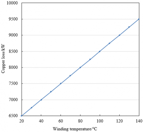
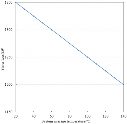
According to the data provided in Figure 3, copper losses and stator core losses increase with the rise in temperature, indicating a positive correlation between the losses of the synchronous condenser and its operating temperature. Specifically, when the winding temperature increases from 20℃ to 140℃, the copper losses increase from 6500 W to 9500 W, with an increase of 3000 W, showing a significant impact of temperature on the losses generated by current passing through the copper windings. Similarly, stator core losses also show a gradual increase with the rise in system average temperature, increasing from 1350 W to 1200 W. The greater the temperature rise, the greater the magnetic losses in the materials. This change indicates that the temperature effect on magnetic materials' losses is significant, especially in terms of the impact on electromagnetic performance, which should not be neglected in the synchronous condenser's operating state. By analyzing the copper losses and stator core losses of the synchronous condenser with respect to temperature changes, the following conclusion can be drawn: the increase in temperature directly contributes to the increase in losses, particularly under high-temperature conditions. The increase in copper losses is particularly significant, indicating that the resistance of the copper windings increases in high-temperature environments, leading to more energy loss. Although the increase in stator core losses is relatively small, it still indicates that temperature promotes magnetic losses in the stator core.
(a)
(b)
Figure 3. Simulation results of the impact of temperature on losses (a) Copper losses as a function of winding temperature (b) Stator core losses as a function of system average temperature
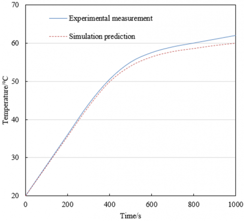
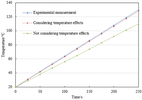
From the data in Figure 4, the temperature trend of the synchronous condenser with respect to time under two different speed conditions shows a certain similarity, but also obvious differences. For the 500 r/min condition, the experimental measurement results show that the temperature starts from the initial 20℃ and gradually increases with the operating time, reaching about 61℃ at 1000 seconds, while the simulated temperature data at this time is 59.4℃. The temperature change trends of both are consistent, with a maximum temperature difference of 1.6℃. This difference indicates that the experimental and simulation results are consistent to some extent, but the simulation results are slightly lower than the experimental data, possibly due to differences in actual cooling effects and material parameters. For the 1200 r/min condition, the experimental measured temperature is significantly higher over time, increasing from 20℃ to 130℃, while the simulated temperature, considering the temperature effect, reaches 128℃, which is very close to the experimental data. Without considering the temperature effect, the simulation temperature is slightly lower, around 110℃. This shows that the temperature effect has a significant impact on the system's temperature rise, especially at higher speeds, where considering the temperature effect can more accurately reflect the actual operating temperature. Based on the comparison and analysis of the experimental data and simulation results, it is evident that speed and temperature effects have a significant impact on the synchronous condenser’s temperature rise. At the 500 r/min low-speed condition, the temperature change trends of the experimental and simulation results are consistent, proving that the temperature rise is mainly influenced by stator copper losses and winding heat dissipation, and the simulation model can effectively predict this process. However, at the 1200 r/min high-speed condition, the temperature rise is significant, and the experimental results and simulations considering temperature effects show little difference, indicating that temperature effects are more pronounced on the equipment performance under high load and high-speed conditions. In particular, when calculating losses, the temperature effect cannot be ignored.
(a)
(b)
Figure 4. Experimental results under two operating conditions (a) 500 r/min (b) 1200 r/min
(a)
(b)
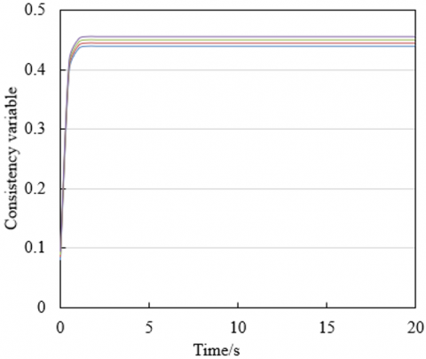
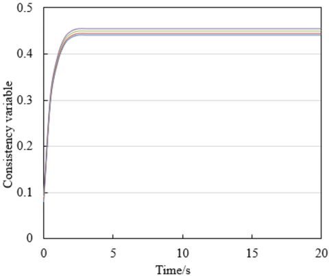
Figure 5. The impact of thermodynamic performance on the control effect of 8 synchronous condensers (a) Without considering thermodynamic performance (b) With considering thermodynamic performance
The experimental results in Figure 5 show a significant difference in the control convergence speed of the synchronous condenser when considering thermodynamic performance and when not considering it. In the case where thermodynamic performance is considered, the simulation results show that the temperature effect has a significant impact on the operating state and regulation process of the synchronous condenser, especially under high speed and long-term operation conditions. As the temperature gradually increases, the system's losses increase, which in turn affects the regulation performance. This rise in temperature requires more time for the synchronous condenser to reach a stable state during the control process.
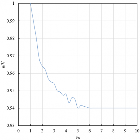
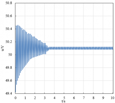
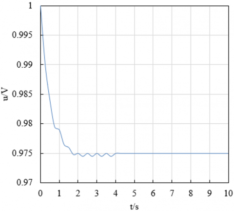
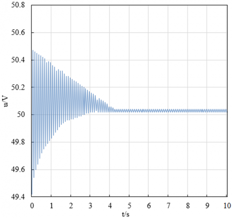
Figures 6 and 7 show the variations in grid voltage and frequency under two scenarios. Specifically, when thermodynamic performance is not considered, the grid voltage stabilizes at 0.94, while when thermodynamic performance is considered, the grid voltage stabilizes at 0.975, showing a significant improvement. Regarding frequency, when thermodynamic performance is not considered, the system frequency stabilizes at 50.12 Hz, while with thermodynamic performance, it stabilizes at 50.4 Hz, further demonstrating the positive impact of temperature effects on the system's dynamic response. This change can be attributed to the effect of thermodynamic performance on the synchronous condenser's reactive power compensation capability, allowing it to respond faster when grid voltage drops, reducing the system's reactive power gap, and thereby improving the voltage and frequency stability of the grid.
From the experimental results, it is clear that the synchronous condenser control strategy considering thermodynamic performance significantly improves grid stability, particularly in voltage and frequency regulation, showing notable improvements. By comparing the final stable values of grid voltage and frequency, it can be seen that the temperature effect plays an important role in optimizing system performance. After considering the temperature effect, the system can respond more quickly and effectively to voltage drops and frequency fluctuations. Especially in the reactive power compensation process, considering the temperature effect makes the synchronous condenser's response faster, reducing the extent of reactive power gaps and power surpluses, thereby improving the quality and stability of the system frequency.
(a)
(b)
Figure 6. Changes in grid stability when building the synchronous condenser control strategy without considering thermodynamic performance (a) Voltage Variation (b) Frequency Variation
(a)
(b)
Figure 7. Changes in grid stability when building the synchronous condenser control strategy considering thermodynamic performance (a) Voltage Variation (b) Frequency Variation
This study focused on the thermodynamic performance of the synchronous condenser and its impact on grid frequency stability. The research is divided into three main parts: first, the calculation of synchronous condenser losses, analyzing energy losses under different operating conditions, and revealing its thermodynamic characteristics under various operating conditions; second, a two-dimensional electromagnetic field simulation of the synchronous condenser was conducted, considering material temperature effects, to evaluate the impact of temperature changes on the device's performance, especially its response and stability under high load conditions; finally, a temperature field CFD simulation model of the synchronous condenser was constructed, and through temperature field analysis, the impact of temperature distribution on grid frequency stability regulation is studied. These studies provide theoretical support for understanding the role of synchronous condensers in the grid and propose strategies for fully considering thermodynamic factors in grid regulation processes.
Through the analysis of experimental data and simulation results, this paper demonstrates the important impact of thermodynamic performance on the synchronous condenser control strategy and grid frequency stability. When thermodynamic effects are not considered, the stability of grid voltage and frequency is poorer, with voltage stabilizing at 0.94 and frequency stabilizing at 50.12 Hz. However, when thermodynamic performance is considered, the grid voltage and frequency stabilize at 0.975 and 50.4 Hz, respectively, showing that the inclusion of temperature effects significantly enhances the system's regulation capability. Specifically, thermodynamic effects improve the synchronous condenser's reactive power compensation ability, enabling it to respond more quickly to grid voltage and frequency fluctuations, optimizing the system's dynamic regulation process. Therefore, considering thermodynamic performance not only improves the quality of grid frequency but also helps to reduce the reactive power gap in the system, enhancing grid stability.
This research revealed the crucial role of synchronous condenser thermodynamic performance in grid frequency stability regulation, particularly in high-load and dynamic response situations. The study shows that considering temperature effects can effectively optimize the synchronous condenser's reactive power compensation ability, thereby improving the system's response speed and regulation accuracy during voltage and frequency regulation. This provides theoretical support for power system optimization control and has important guidance for future grid scheduling and synchronous condenser design.
[1] Elizabeth, A.O., Oyaka, O.S., Orovwode, H., Airoboman, A.E., Gabriel, S., Nwenenda, D.H. (2024). Identifying key reliability factors in micro-grid systems using principal component analysis. Journal Européen des Systèmes Automatisés, 57(1): 303-309. https://doi.org/10.18280/jesa.570130
[2] Lorenzini, G., Kamarposhti, M.A., Solyman, A.A.A. (2021). Optimal location of sectionners and distributed generation resources to improve reliability in distribution networks. Mathematical Modelling of Engineering Problems, 8(2): 165-169. https://doi.org/10.18280/mmep.080201
[3] Kobibi, Y.I.D., Djehaf, M.A., Khatir, M., Ouadafraksou, M. (2022). Continuation Power Flow Analysis of Power System Voltage Stability with Unified Power Flow Controller. Journal of Intelligent Systems and Control, 1(1): 60-67. https://doi.org/10.56578/jisc010106
[4] Al-Kaoaz, H.N.A., Alsammak, A.N.B. (2024). The impact of hybrid power generations on a power system's voltage stability. Journal Européen des Systèmes Automatisés, 57(2): 541-549. https://doi.org/10.18280/jesa.570223
[5] Saha, S., Saleem, M.I., Roy, T.K. (2023). Impact of high penetration of renewable energy sources on grid frequency behaviour. International Journal of Electrical Power & Energy Systems, 145: 108701. https://doi.org/10.1016/j.ijepes.2022.108701
[6] Li, C., Yang, Y., Cao, Y., Wang, L., Blaabjerg, F. (2022). Frequency and voltage stability analysis of grid-forming virtual synchronous generator attached to weak grid. IEEE Journal of Emerging and Selected Topics in Power Electronics, 10(3): 2662-2671. https://doi.org/10.1109/JESTPE.2020.3041698
[7] Chen, J., Si, W., Liu, M., Milano, F. (2023). On the impact of the grid on the synchronization stability of grid-following converters. IEEE Transactions on Power Systems, 38(5): 4970-4973. https://doi.org/10.1109/TPWRS.2023.3284262
[8] Saleem, M.I., Saha, S., Roy, T.K., Ghosh, S.K. (2024). Assessment and management of frequency stability in low inertia renewable energy rich power grids. IET Generation, Transmission & Distribution, 18(7): 1372-1390. https://doi.org/10.1049/gtd2.13129
[9] Hu, Y., Wang, X., Huang, T., Lei, X., Wang, T. (2022). An optimal frequency control method of asynchronous power grid considering multi-HVDC emergency power support. IEEE Access, 10: 78011-78021. https://doi.org/10.1109/ACCESS.2022.3192569
[10] Zhao, Y., Xie, C., Peng, C., Zou, J. (2024). Passivity-based design of frequency adaptive repetitive controller for LCL-type grid-connected inverters. IEEE Transactions on Power Electronics, 39(4): 4017-4028. https://doi.org/10.1109/TPEL.2023.3347723
[11] Teleke, S., Abdulahovic, T., Thiringer, T., Svensson, J. (2008). Dynamic performance comparison of synchronous condenser and SVC. IEEE Transactions on Power Delivery, 23(3): 1606-1612. https://doi.org/10.1109/TPWRD.2007.916109
[12] Li, C., Liu, M., Guo, Y., Ma, H., Wang, H., Yuan, X. (2022). Cost analysis of synchronous condenser transformed from thermal unit based on LCC theory. Processes, 10(9): 1887. https://doi.org/10.3390/pr10091887
[13] Ma, M., He, P., Li, Y., Li, H., Jiang, M., Wu, Y. (2021). Fault diagnosis method based on multi-source information fusion for weak interturn short circuit in synchronous condensers. IET Electric Power Applications, 15(9): 1245-1260. https://doi.org/10.1049/elp2.12094
[14] Mahmud, S.U., Ansary, M.N., Deeba, S.R. (2022). Improvement of system strength under high wind penetration: A techno-economic assessment using synchronous condenser and SVC. Energy, 246: 123426. https://doi.org/10.1016/j.energy.2022.123426
[15] Wang, J.F., Yin, H., Li, D.Y. (2024). Control strategy of dual power supply excitation system for HTS synchronous condenser. IEEE Access, 12: 183823-183831. https://doi.org/10.1109/ACCESS.2024.3505901
[16] Dziendziel, A., Rzepka, P., Szablicki, M. (2023). Przeglad rozwiazan kompensatorów synchronicznych na swiecie. Przeglad Elektrotechniczny, 99(9): 15-18. http://doi.org/10.15199/48.2023.09.03
[17] Bi, X.S., Wang, L.K., Zhou, M.H. (2021). Research on electromagnetic field, eddy current loss and heat transfer in the end region of synchronous condenser with different end structures and material properties. Energies, 14(15): 4636. https://doi.org/10.3390/en14154636
[18] Marrazi, E., Yang, G., Weinreich-Jensen, P. (2018). Allocation of synchronous condensers for restoration of system short-circuit power. Journal of Modern Power Systems and Clean Energy, 6(1): 17-26. https://doi.org/10.1007/s40565-017-0346-4
[19] Jiang, M., Ma, H., Zhang, Y., Chen, X., Zhao, X. (2021). Reactive power characteristics and vibration properties under SISC in synchronous condensers. International Journal of Electrical Power & Energy Systems, 133: 107318. https://doi.org/10.1016/j.ijepes.2021.107318
[20] Wei, C., Li, H.Y., Cheng, M. (2021). Discrimination method of interturn short-circuit and resistive unbalance faults for synchronous condenser. IEEE Access, 9: 129706-129717. https://doi.org/10.1109/ACCESS.2021.3112472
[21] Igbinovia, F.O., Fandi, G., Ahmad, I., Muller, Z., Tlusty, J. (2018). Modeling and simulation of the anticipated effects of the synchronous condenser on an electric-power network with participating wind plants. Sustainability, 10(12): 4834. https://doi.org/10.3390/su10124834
[22] Roux, A., Bekker, B., Dalton, A. (2022). Synchronous condensers as a viable inertia support mechanism on the future South African grid. Energy for Sustainable Development, 69: 192-201. https://doi.org/10.1016/j.esd.2022.06.010
[23] Jia, J., Yang, G., Nielsen, A.H., Gevorgian, V. (2019). Investigation on the combined effect of VSC-based sources and synchronous condensers under grid unbalanced faults. IEEE Transactions on Power Delivery, 34(5): 1898-1908. https://doi.org/10.1109/TPWRD.2019.2914342