Lujain S. Hyal*![]() | Jalal M. Jalil
| Jalal M. Jalil![]() | Abduljabbar O. Hanfesh
| Abduljabbar O. Hanfesh![]()
© 2024 The authors. This article is published by IIETA and is licensed under the CC BY 4.0 license (http://creativecommons.org/licenses/by/4.0/).
OPEN ACCESS
Access to potable water is essential for human existence. This work aims to enhance the performance of single-slope solar still. Two solar stills were employed: A conventional solar still (CSS)served as a reference, and a modified solar still (MSS) which featured a novel design with a floating absorber surface. The objective is to increase the productivity and efficiency of solar still by enhancing the evaporation surface area using wick materials. Multiple ratios of wick material (25%, 50%, 75%, and 100%) with and without an external condenser were examined to assess their influence on production. Computational Fluid Dynamics (CFD) program was employed to numerically simulate solar distillation under natural and forced convection circumstances, therefore confirming the accuracy of the experimental findings. Based on the outcomes, the increase in productivity reached 25%, 50%, 75%, and 100% wick coverage for the MSS were around 33%, 66%, 45%, and 16% higher than the productivity achieved with the CSS, respectively. With the external condenser, the enhancements increased to 35%, 75%, 50%, and 27% compared to the CSS. Daily efficiency of the MSS with wick was 19.19%, while the efficiency increased to 27.13% when both the wick and condenser were used.
external condenser, still efficiency, Computational Fluid Dynamics (CFD), jute wick, productivity
When compared to other energy sources, solar energy is ecologically clean, far less expensive, renewable, readily accessible, and free of hazardous emissions and nearby contamination [1]. Lack of drinkable water is perceived as an obstacle in developing countries. Even though Iraq is a country with many rivers, barely 40% of its population lives in cities, some individuals reside in rural areas, arid regions, and even urban districts, and they may never have the opportunity to obtain this water [2]. Solar energy desalination is a workable way to generate drinkable water, particularly in isolated places so, Desalinated freshwater is therefore in greater demand every day [3, 4]. Therefore, numerous researchers are attempting to expand and promote the solar energy market to provide humans with enough freshwater sources due to the limited availability and high cost of other energy types sources [5]. Consequently, water treatment is typically required to provide fresh water from brackish or saltwater. So, water distillation and purification are always needed. One such method that assists in tackling the shortage of drinking water is solar desalination using solar radiation and energy to separate salt from water. Solar desalination is classified based on methods and sources of energy. A solar still is a small device that uses solar energy, which is a free, accessible, and renewable source of power. This is the most extensively utilized type of solar desalination system. This process results in the removal of microbiological organisms and contaminants like salts and other heavy metals, leaving us with pure water at the end. The main drawback of utilising solar stills for desalination is their limited productivity and efficiency. 2-4 L/m2 day of distillate can normally be obtained by
Essa et al. [26] improved the efficiency and productivity of pyramid solar stills (
Previous studies have not extensively examined the use of novel designs that combine floating absorbers with varying proportions of wick materials. Furthermore, the comprehensive effect of these developments, in conjunction with external condensers to improve performance has not been thoroughly examined. The objective of this study is to develop a modified solar still (MSS) with a distinctive design that includes a floating absorber surface having different ratios (25%, 50%, 75%, and 100%) of wick material to enhance the evaporation surface area. The study conducted experiments to evaluate the performance CSS with the MSS to determine the optimal ratio of wick material that maximizes production. Furthermore, Computational Fluid Dynamics (CFD) software will be utilized to simulate solar distillation under both natural and induced convection conditions. Also, it includes the incorporation of external condensers to find the ideal configuration for producing the highest possible yield, the study will analyze the productivity and efficiency of the CSS and MSS with and without the external condenser experimentally and numerically to validate the outcomes of the experiment.
2.1 Conventional solar still (CSS)
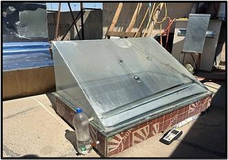
Galvanized steel plate with a thickness of 0.15 cm was used to construct the CSS basin and has dimensions of 110×70×12 cm. The low side, high side, length, and width of the solar stills are 12, 48, 110, and 70 cm, respectively. To close the solar stills and simplify the process of condensation and collection, it is important for the cover to be tilted at an appropriate angle, as shown in Figure 1. This will allow the water droplets to easily flow into the collecting trough without any of them returning to the basin, a 4 mm thick glass cover was employed. The glass has a transmittance of 97% and is tilted 35° to the south to capture as much solar energy as possible all year round. A small sloped basin was built into the bottom of the glass to catch the condensate and move it to a tuned cylinder. To avoid any vapour leakage from the solar still systems, the solar still was hermetically sealed with silicon material. Insulating a solar still is essential since it reduces the amount of heat that is lost and improves the overall performance of the system. The insulation is strategically applied to the sides and bottom of the stills from the outside in order to minimise heat dissipation to the surrounding environment. The basins of both stills were installed on support structures made of 16 mm wood and 5 cm thick foam sheets.
Figure 1. Photo of conventional solar still
2.2 Modified solar still (MSS)
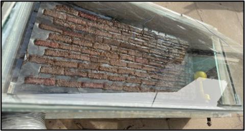
The MSS has the identical dimensions as the CSS. MSS had an absorption surface parallel to the original absorber surface. Small pieces of foam 2.5×2.5 cm are being used to float the upper absorber. The upper absorber was made of an aluminum sheet 100×55×0.05 cm with several cracks (150). The dimensions of one crack were 10×2×0.2 cm. Wick cords were put into the absorber's cracks and hung to draw out the salt water and moisten the wick's top surface, as shown in Figure 2. Consequently, the enhanced still experiences an increase in its evaporation rate. The solar still is fed with saline water from a constant head tank, where the water is at a depth of 2 cm. The water was kept between the two absorbers. Jute fiber was used as the wick material. This material was used in different proportions relative to the absorption surface area (25%, 50%, 75% and 100%). The wick cords draw out just the right amount of saline water to evaporate, without taking away or adding too much heat to boost solar still production. Therefore, there is no loss of hot water.
Figure 2. Photo of modified solar still
2.3 Thin absorber surface
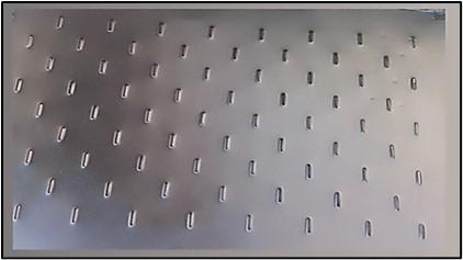
MSS had an absorption surface parallel to the original absorber surface of the basin. The absorber surface was coated in black paint. The dimension of absorber were (100×55×0.15 cm) with a number of cracks. The dimensions of one crack were (10×0.2×0.2 cm). The absorber with cracks shown in Figure 3.
Figure 3. The thin absorber before coated with black paint
2.4 Wick materials
Wick cords of different materials (jute fiber, velvet, solid cotton) were used passed through the cracks of the absorber and dangled to draw out the saline water and moisten the upper surface of the wick, as shown in Figure 4. The dimension of cord is (15×10×3 cm). This material was used in different proportions relative to the absorption surface area (25%, 50%, 75% and 100%). The purpose of this alteration is to enhance the evaporation rate by augmenting the surface area and harnessing the capillary effect of the materials. Additionally, it serves to mitigate energy inefficiency.
Figure 4. Wick used in the experiment
2.5 External condenser
The condenser outer shell are made of galvanized steel mounted on a stand behind the still. The condenser consisted of two parts, the first part was an extract fans have been installed at the top left and bottom right corners of the back of solar still. The top fan used for extracting vapor from evaporative chamber of solar still to reservoir through flexible hose which distill it an external jug. The power of the fan is 8 W with maximum rotational speed of 0.6 m/s. The second part was cooling pipe made of copper material (serpentine) that was 5 meters in length and had a diameter of 0.8 cm. This cooling pipe is rolling and the diameter must keep constant along the whole tube with 26 turns with a perimeter 180 mm of each turn. The reservoir has a dimension of 250, 300, 500 mm in length, width and height respectively served as condensing space. A graded container attached below the reservoir to collect the condensate water as shown in Figure 5.
(1) glass of solar still, (2) hose of vapor, (3) the condenser, (4) heat exchanger, (5) distilled water collection hole, (6) the vapor inlet
Figure 5. Photographic view of the external condenser components
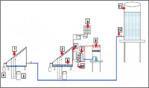
A submersible pump was used in order to push the water between the cooling tower and copper tube and the overall system Schematic diagram was shown in Figure 6.
(1) CSS, (2) MSS, (3) thermeter, (4) fresh water, (5) floating absorber, (6) D.C fan, (7) the condenser, (8) cooling tower, (9) PV panal, (10) fresh water, (11) storage tank, (12) control valve
Figure 6. Schematic diagram of overall system
2.6 PV panel
Panel solar is polycrystalline type comprises 36. The PV system is capable of charging the battery to its maximum capacity while simultaneously serving enormous loads in sunny conditions. The PV system serves the demand and does not charge the battery during cloudy weather or at night. The data sheet of the solar PV panels are listed in Table 1. The battery will gradually release the stored energy until it is depleted, causing the power supply to the load to be interrupted before the intended duration. As shown in Figure 7.
Figure 7. The solar PV panel
Table 1. The data sheet of the solar PV panels
|
Parameter |
Value |
|
Maximum operating voltage (Vmp) |
18 V |
|
Maximum operating current (Imp) |
2.78 A |
|
Open circuit voltage (Voc) |
22.05 V |
|
Short circuit current (Isc) |
2.79 A |
|
Maximum power (Pm) |
50 W |
|
Panel dimensions |
67 cm×55 cm |
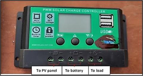
2.7 Charge controller
A charge controller functions as a voltage or current regulator, preventing batteries from being overcharged It regulates the voltage and current that travel from the solar panel to the battery. A panel primarily generates power in the voltage range of 12-20V. If not regulated, this could cause damage to the batteries by overcharging them. Figure 8 depicts the solar charge controller.
Figure 8. Solar charge controller device
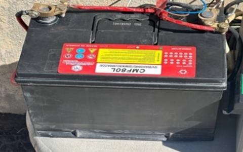
2.8 Battery
Throughout the day, the photovoltaic panel produces electrical energy and replenishes the battery. The accumulated electrical energy can be transmitted to the load at any given time throughout system operation. To keep the load operating even when solar energy generation is minimal, a solar battery (12V/74 Ah). This battery also operates the fans that are connected at the back of solar still, which draw in vapor for the purpose of condensing it outside, as shown in Figure 9.
Figure 9. Battery used with PV panel in the experiment
In this work, the two solar stills were tested in identical meteorological conditions. The experiment was performed in October 2023. The test system was set up in Baghdad (latitude 33.3152°N and longitude 44.3661°E). To maximize its exposure to normal solar radiation, the test rig was oriented towards the south. As is commonly known, solar still performance can be noticed by estimating the yield at the end of each day.
The measurement equipment specifications are given in Table 2. Temperature measurements were made at different sites using K-type thermocouples which calibrated in the Central Organization for Standardization and Quality Control (COSQC). The temperatures of (absorber, glass in/out, water, ambient temperatures) were recorded every hour using a data logger.
Equation following has been used to compute the uncertainties related to the results. The uncertainties of the measured data were estimated using [34]. Equation below has been adopted, the output, denoted as $X$, is a formula that is determined by the independent parameters $v1,~v2,~v3~to~vn$. So, $X=~X~\left( v1,~v2,~v3~to~vn \right),$ where$~{{U}_{R}}~$represents the variable uncertainty,$~$and $U1,~U2,~U3$ to $Un$ represent the uncertainties of the independently measured variables. The error introduced in the output can be approximated by considering the propagation of uncertainties through the formula that relates the parameters to the output. Therefore, the error in the result can be given by the following expression:
${{\text{U}}_{\text{R}}}=[{{\left( \frac{\partial \text{x}}{\partial {{\text{v}}_{1}}}\text{U}1 \right)}^{2}}+{{\left( \frac{\partial \text{x}}{\partial {{\text{v}}_{2}}}{{\text{U}}_{2}} \right)}^{2}}+{{\left( \frac{\partial \text{x}}{\partial {{\text{v}}_{3}}}{{\text{U}}_{3}} \right)}^{2}}+\ldots \text{ }\!\!~\!\!\text{ }{{\left( \frac{\partial \text{x}}{\partial {{\text{v}}_{\text{n}}}}{{\text{U}}_{\text{n}}} \right)}^{2}}]\hat{\ }0.5$
Table 2. Technical characteristics of the measuring tools used in the experiment
|
No. |
Instrument |
Range |
Accuracy |
Error |
|
1 |
Temperature logger |
-200℃-1370℃ |
5% |
0.36% |
|
2 |
K- Type thermocouple |
-50.1-200.0℃ |
± 0.4% +1℃ |
0.36% |
|
3 |
Solar meter |
0-2000 W/m2 |
± 5%, ± 10 W/m2 |
± 2.0% |
|
4 |
Wind meter |
0.4-30 m/s |
± 0.1 m/s |
± 2% |
|
5 |
Measuring flask |
0-250 ml |
± 2 mL |
1% |
|
6 |
Humidity measurement |
10 RH– 99% RH |
± 5% RH |
1% |
The built-in CFD program was utilized to simulate every region of the solar still. This program is well-known for producing accurate outcomes when analyzing the condensation and evaporation rates associated with this particular method of water distillation (including conduction, convection, and radiation). Moreover, the results presented can be utilized to enhance the functionality of the solar still to increase the daily production of potable water. The following equations represent the governing equations of a single slope solar still based on the Navier-Stokes equations: conservation of mass, momentum, and energy. These equations are utilized for the analysis and construction of the mathematical model [35, 36]:
(1). Equation of continuity (The mass conservation equation):
$\rho ~\left( \frac{\partial U}{\partial x}+\frac{\partial V}{\partial y}+\frac{\partial W}{\partial z} \right)=0$ (1)
(2). Equation of momentum Navier–Stokes Equation (The conservation of momentum equation):
(I) X- Direction
$\frac{\partial {{U}^{2}}}{\partial x}+\frac{\partial UV}{\partial y}+\frac{\partial UW}{\partial z}=-\frac{1}{\rho }\frac{\partial P}{\partial x}+\frac{\partial }{\partial x}\left( \nu \frac{\partial U}{\partial x} \right)+\frac{\partial }{\partial y}\left( \nu \frac{\partial U}{\partial y} \right)+\frac{\partial }{\partial z}\left( \nu \frac{\partial U}{\partial z} \right)$ (2)
(II) Y-Direction
$\frac{\partial UV}{\partial x}+\frac{\partial {{V}^{2}}}{\partial y}+\frac{\partial VW}{\partial z}=-\frac{1}{\rho }\frac{\partial P}{\partial y}+\frac{\partial }{\partial x}\left( \nu \frac{\partial V}{\partial x} \right)+\frac{\partial }{\partial y}\left( \nu \frac{\partial V}{\partial y} \right)+\frac{\partial }{\partial z}\left( \nu \frac{\partial V}{\partial z} \right)+\rho g$ (3)
(III) Z-Direction
$\frac{\partial UW}{\partial x}+\frac{\partial VW}{\partial y}+\frac{\partial {{W}^{2}}}{\partial z}=-\frac{1}{\rho }\frac{\partial P}{\partial z}+\frac{\partial }{\partial x}\left( \nu \frac{\partial W}{\partial x} \right)+\frac{\partial }{\partial y}\left( \nu \frac{\partial W}{\partial y} \right)+\frac{\partial }{\partial z}\left( \nu \frac{\partial W}{\partial z} \right)$ (4)
(3). Equation of energy (Energy conservation equation):
$\frac{~\partial UT}{\partial x}+\frac{\partial VT}{\partial y}+\frac{\partial WT}{\partial z}=\frac{\partial }{\partial x}\left( \Gamma \frac{\partial T}{\partial x} \right)+\frac{\partial }{\partial y}\left( \Gamma \frac{\partial T}{\partial y} \right)+\frac{\partial }{\partial z}\left( \Gamma \frac{\partial T}{\partial z} \right)$ (5)
The diffusion coefficient $\text{ }\!\!\Gamma\!\!\text{ }$ is calculated by, $\text{ }\!\!\Gamma\!\!\text{ }=\frac{\nu }{Pr}$, where ($Pr=\frac{\mu {{C}_{p}}}{k}$) is the fluid Prandtl number.
(4). Equation of concentration:
$U~\frac{\partial C}{\partial x}+V~\frac{\partial C}{\partial y}+W~\frac{\partial C}{\partial Z}=D\frac{{{\partial }^{2}}C}{\partial {{x}^{2}}}+D\frac{{{\partial }^{2}}C}{\partial {{y}^{2}}}+D\frac{{{\partial }^{2}}C}{\partial {{z}^{2}}}+{{S}_{c}}$ (6)
To analyze and construct the mathematical model of the governing equations of the SSSS, many assumptions can be used:
1. The flow occurs inside a still enclosure for CSS and case 1 (wick only) is regarded to be natural convection, laminar, and 3D. For case 2 (wick with condenser), the flow is regarded to be mixed convection, laminar, and 3D.
2. Due to the effective insulation of the solar still's side walls, it is expected that heat losses at these surfaces are minimal, if there are any. The solar still is presumed to be hermetically sealed. Therefore, there is no seepage of vapour or water.
3. The water level in the basin remains constant.
4. All pieces of wick are wet.
(5). Boundary conditions:
a) At all walls of solar still: (u=v=w=0), no-slip condition
b) At $X$= 0$,~X=Lx~;\text{ }\!\!~\!\!\text{ }Z=0,~Z=Lz$ are assumed an insulated: ∂T/∂n=0
c) At y=0, T= ${{T}_{w}}$ and 0 < y < 0.6 m, T= ${{T}_{g}}$
d) At y=0, T= ${{T}_{f}}$ or ${{T}_{wi}}$ ; 0 < y < 0.6 m, T= ${{T}_{g}}$
e) T =T in, win = 0.6 m/s
f) T= T out, wout = -0.6 m/s
By using the energy conservation equation with the concentration equations, we can identify the attributes of the components of the solar still, such as the glass cover and absorber plate, basin plate, saline water, and wick material. The energy balance equations for each part of the solar still model are detailed below [37, 38]:
1- Energy balance of the glass cover
The energy balance equation for glass include the solar energy that is absorbed. Heat energy dissipated into the surrounding atmosphere. The glass cover is subjected to solar radiation, resulting in thermal convection. Hence, the following heat and energy concepts are used through the numerical simulation [39]:
${{\text{I}}_{\text{t}}}{{\text{ }\!\!\tau\!\!\text{ }}_{\text{g}}}\text{ }\!\!~\!\!\text{ }{{\text{A}}_{\text{g}}}+{{q}_{r}}_{w-g}+{{q}_{cond}}_{h-gi}={{q}_{c,~g-am}}+{{q}_{r,~g-am}}+{{M}_{g}}\frac{d{{T}_{g}}}{dt}$ (7)
${{\text{q}}_{\text{r},\text{w}-\text{g}}}=\text{ }\!\!\sigma\!\!\text{ }{{\text{ }\!\!\varepsilon\!\!\text{ }}_{\text{wg}}}\text{ }\!\!~\!\!\text{ }{{\text{A}}_{\text{w}}}\left( {{\left( {{\text{T}}_{\text{w}}}+273.15 \right)}^{4}}-{{\left( {{\text{T}}_{\text{g}}}+273.15 \right)}^{4}} \right)$ (8)
where:
$\varepsilon_{\mathrm{wg}}=\left(\left(\frac{1}{\varepsilon_{\mathrm{w}}}\right)+\left(\frac{1}{\varepsilon_{\mathrm{g}}}-1\right)\right)^{-1}$ (9)
The thermal radiation exchange between the glass cover and the surrounding environment [40]:
${{\text{q}}_{\text{r},\text{ }\!\!~\!\!\text{ g}-\text{am}}}={{\text{h}}_{\text{r},\text{g}-\text{am}}}{{\text{A}}_{\text{t}}}\left( {{\text{T}}_{\text{g}}}-{{\text{T}}_{\text{am}}} \right)$ (10)
where,
${{\text{h}}_{\text{r}}}\text{g}-\text{a}=\text{ }\!\!~\!\!\text{ }\!\!\sigma\!\!\text{ }\!\!\varepsilon\!\!\text{ }\left[ {{\left( {{\text{T}}_{\text{g}}}+273 \right)}^{2}}+\frac{{{\left( {{\text{T}}_{\text{s}}}+273 \right)}^{2}}\left[ \left( {{\text{T}}_{\text{g}}}+{{\text{T}}_{\text{s}}}+546 \right) \right]\left( {{\text{T}}_{\text{g}}}-{{\text{T}}_{\text{s}}} \right)}{{{\text{T}}_{\text{g}}}-{{\text{T}}_{\text{a}}}} \right)$ (11)
${{\text{q}}_{\text{c}}}\text{g}-\text{am}={{\text{h}}_{\text{w}}},\text{g}-\text{a }\!\!~\!\!\text{ }{{\text{A}}_{\text{t}}}\left( {{\text{T}}_{\text{g}}}-{{\text{T}}_{\text{am}}} \right)$ (12)
$where,~{{h}_{w}}=2.8+3{{\text{V}}_{\text{w}}}\text{ }\!\!~\!\!\text{ if }\!\!~\!\!\text{ v}\le 5\text{ }\!\!~\!\!\text{ }\left( \frac{\text{m}}{\text{s}} \right)$ (13)
${{\text{h}}_{\text{w}}}=2.8+3.8{{\text{V}}_{\text{w}}}\text{ }\!\!~\!\!\text{ if }\!\!~\!\!\text{ v}>5\text{ }\!\!~\!\!\text{ }\left( \frac{\text{m}}{\text{s}} \right)$ (14)
${{T}_{s}}=0.0552*T_{a}^{1.5}$ (15)
$~{{q}_{cond,~h-g}}={{h}_{cond,~h-g}}{{A}_{t}}\left( {{T}_{h}}-{{T}_{g}} \right)$ (16)
$where:~{{h}_{cond,~h-g}}=70.93~{{\left[ sin\theta ~\left( {{T}_{h}}-Tg \right)L \right]}^{\frac{1}{4}}}$ (17)
2- Energy balance of the basin water which relies on the following term:
${{\text{I}}_{\text{t}}}{{\text{ }\!\!\tau\!\!\text{ }}_{\text{g}}}{{\text{ }\!\!\tau\!\!\text{ }}_{\text{w}}}\text{ }\!\!~\!\!\text{ }{{\text{A}}_{\text{w}}}+{{q}_{c}}_{b-w}={{q}_{e,w-g}}+{{q}_{c,w-g}}+{{q}_{r}}_{w-g}+{{M}_{w}}\frac{d{{T}_{w~}}}{dt}$ (18)
The evaporative heat transfer coefficient between water and glass is [41]:
${{\text{h}}_{\text{e},\text{fw}-\text{g}}}=\left( 16.237\text{*}{{10}^{-3}} \right)\frac{{{\text{h}}_{\text{c},\text{w}-\text{g}}}\left( {{\text{P}}_{\text{w}}}-{{\text{P}}_{\text{g}}} \right)}{{{\text{T}}_{\text{w}}}-{{\text{T}}_{\text{g}}}}$ (19)
${{\text{P}}_{\text{w}}}={{\text{e}}^{\left( 25.317-\left( \frac{5144}{{{\text{T}}_{\text{w}}}} \right) \right)}}$ (20)
${{\text{P}}_{\text{w}}}={{\text{e}}^{\left( 25.317-\left( \frac{5144}{{{\text{T}}_{\text{g}}}} \right) \right)}}$ (21)
The convective heat transfer coefficient between water and glass is [42]:
${{\text{h}}_{\text{c},\text{fw}-\text{g}}}=0.884{{\left( \left( {{\text{T}}_{\text{w}}}-{{\text{T}}_{\text{g}}} \right)+\frac{\left( {{\text{P}}_{\text{w}}}-{{\text{P}}_{\text{g}}} \right)\left( {{\text{T}}_{\text{w}}}+273.15 \right)}{268900-{{\text{P}}_{\text{w}}}}\text{ }\!\!~\!\!\text{ } \right)}^{\frac{1}{3}}}$ (22)
${{q}_{r,w-g}}=\sigma {{\varepsilon }_{wg}}~{{A}_{w}}\left( {{\left( {{T}_{w}}+273.15 \right)}^{4}}-{{\left( {{T}_{g}}+273.15 \right)}^{4}} \right)$ (23)
where:
$\varepsilon_{\mathrm{wg}}=\left(\left(\frac{1}{\varepsilon_{\mathrm{w}}}\right)+\left(\frac{1}{\varepsilon_{\mathrm{g}}}-1\right)\right)^{-1}$ (24)
The Nusselt number relation was used to determine its value:
${{q}_{c,~b-w}}={{h}_{c,b-w}}~{{A}_{y}}~\Delta T$ (25)
$Nu=\frac{hL}{{{k}_{w}}}$ = $0.069~R_{a}^{\frac{1}{3}}~P_{r}^{0.074}$ (26)
The study of Nwosu et al. [43] indicates that the actual heat transfer rate is unaffected by the characteristic length. Therefore, the convective coefficient is represented as:
${{\text{h}}_{\text{c}}}_{\text{b}-\text{w}}=0.069\text{*}{{\text{k}}_{\text{w}}}\text{ }\!\!~\!\!\text{ }{{\left( \text{g* }\!\!\beta\!\!\text{ *}\left( \text{Tb}-{{\text{T}}_{\text{w}}} \right)\text{v }\!\!\alpha\!\!\text{ } \right)}^{\frac{1}{3}}}\frac{\text{p}{{\text{r}}^{0.074}}}{L}~$ (27)
$where:~\beta =\frac{1}{Tfw+Tw}$ (28)
3- Energy balance of the basin plate:
The absorber plate's energy balance equation is given by:
$\left( 1-{{\alpha }_{g}} \right)\left( 1-{{R}_{g}} \right)\left( 1-{{R}_{w}} \right){{\alpha }_{b}}={{q}_{c}}\left( b-w \right)+~{{q}_{losses}}\left( b-a \right)+{{M}_{b}}\frac{d{{T}_{b}}}{dt}$ (29)
where:
${{q}_{losses}}\left( b-a \right)={{U}_{{{b}_{,a}}}}\left( {{A}_{b}}+{{A}_{sides}} \right)*\left( {{T}_{b}}-{{T}_{a}} \right)$ (30)
${{\text{U}}_{\text{b},\text{a}}}={{\left( \frac{{{\text{L}}_{\text{ins}}}}{{{\text{k}}_{\text{ins}}}}+\frac{1}{{{\text{h}}_{\text{t},\text{b},\text{a}}}} \right)}^{-1}}$ (31)
Energy balance of the floating wick is given as follows:
${{I}_{t}}\left( 1-{{\alpha }_{g}} \right)\left( 1-{{R}_{g}} \right)\left( 1-{{R}_{wi}} \right){{\alpha }_{wi}}={{q}_{cond}}_{wi-w}+{{q}_{e,w-g}}+{{q}_{c,w-g}}+{{q}_{r}}_{w-g}+{{q}_{cond}}_{f-wi~}$ (32)
${{q}_{cond\left( wi-w \right)}}=\frac{{{K}_{w}}{{A}_{w}}\left( {{T}_{wi}}-{{T}_{w}} \right)}{Lw}$ (33)
Energy balance of the floating absorber is given as follows:
${{\text{I}}_{\text{t}}}\left( 1-{{\text{ }\!\!\alpha\!\!\text{ }}_{\text{g}}} \right)\left( 1-{{\text{R}}_{\text{g}}} \right)\left( 1-{{\text{R}}_{\text{fw}}} \right){{\text{ }\!\!\alpha\!\!\text{ }}_{\text{wi}}}={{\text{q}}_{\text{cond}}}_{\text{f}-{{\text{w}}_{\text{i}}}}+{{\text{q}}_{\text{cond}}}_{\text{f}-\text{w }\!\!~\!\!\text{ }}$ (34)
Energy balance of the water basin is given as follows:
${{I}_{t}}\left( 1-{{\alpha }_{g}} \right)\left( 1-{{R}_{g}} \right)\left( 1-{{R}_{wi}} \right){{\alpha }_{wi}}+{{q}_{cond}}_{wi-w}+{{q}_{cond}}_{f-w}={{q}_{c}}_{f-w}$ (35)
Energy balance of the water basin is given as follows:
The heat and mass transfer is similar to above case, except the energy reflecting from the wick material and water through convection ${{q}_{c}}$ and evaporation ${{q}_{ev}}~$will go into the flowing air first (defined as ${{q}_{fc}}_{w-f}$ and ${{q}_{ev}}$) instead of going directly to glass. Then, the flowing air (the flow) will release part of its energy to the glass through convection ${{q}_{c}}_{f-g}$.
The forced convective heat transfer rate between the basin water and the flow can be computed by [44]:
${{q}_{fc}}_{wi-fl}=3.91{{\left( \frac{V}{{{D}_{h}}} \right)}^{0.5}}\left( {{T}_{w}}-{{T}_{fl}} \right)$ (36)
The forced convective heat transfer rate between the glass and the flow can be computed by:
${{q}_{fc}}_{fl-g}=2.8\left( \frac{{{V}^{\frac{4}{5}}}}{{{L}^{\frac{1}{5}}}} \right)\left( {{T}_{fl}}-{{T}_{g}} \right)$ (37)
The energy and mass balances for the glass:
${{\text{I}}_{\text{t}}}{{\text{ }\!\!\tau\!\!\text{ }}_{\text{g}}}\text{ }\!\!~\!\!\text{ }{{\text{A}}_{\text{g}}}+{{q}_{r}}_{w-g}+{{q}_{cond}}_{h-gi}+~{{q}_{fc}}_{fl-g}={{q}_{c,~g-am}}+{{q}_{r,~g-am}}+{{M}_{g}}$ (38)
The energy and mass balances for the wick material:
${{I}_{t}}\left( 1-{{\alpha }_{g}} \right)\left( 1-{{R}_{g}} \right)\left( 1-{{R}_{wi}} \right){{\alpha }_{wi}}={{q}_{cond}}_{wi-w}+{{q}_{e,wi-g}}+{{q}_{c}}_{fl-g}+{{q}_{fc}}_{wi-fl}+{{q}_{r}}_{w-g}+{{q}_{cond}}_{f-wi}$ (39)
The hourly productivity in (kg/m2) of the CSS can be calculated by [44, 45]:
${{m}^{.}}=70.93~{{\left[ sin\theta ~\left( {{T}_{w}}-Tg \right)L \right]}^{\frac{1}{4}}}\frac{\left( {{T}_{w}}-Tg \right)}{hfg}$ (40)
For modified still:
${{m}^{.}}=70.93~{{\left[ sin\theta ~\left( {{T}_{wi}}-Tg \right)L \right]}^{\frac{1}{4}}}~\left( {{T}_{fw}}-Tg \right)hf{{g}^{-1}}*{{r}_{wi}}~where~{{r}_{fw}}=\frac{{{A}_{b}}}{{{A}_{wi}}}$ (41)
${{h}_{fg}}=2.39*{{10}^{6}}*(1-\left( 9.48*{{10}^{-4}} \right)*\left( {{T}_{w}}+1.313*{{10}^{-7}}*T{{w}^{2}} \right)-\left( 4.79*{{10}^{-9}}*T{{w}^{3}} \right)$ (42)
The hourly thermal efficiency of the system is computed as:
${{\eta }_{h}}=\frac{m_{d}^{.}*{{h}_{fg}}}{I*A*3600}*100\%$ (43)
The overall thermal efficiency:
${{\eta }_{o}}=\frac{\text{ }\!\!\Sigma\!\!\text{ }m_{d}^{.}*{{h}_{fg}}}{\text{ }\!\!\Sigma\!\!\text{ }I*A*3600}*100\%$ (44)
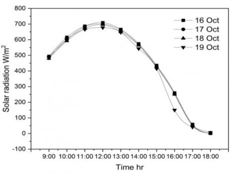
This work used wick material with different wick ratios to investigate MSS performance both experimentally and numerically. The hourly temperatures of the still water, glass cover, vapor, absorber, and productivity for conventional and modified solar stills were recorded. In the days of the experiment solar radiation and variations in ambient temperature and wind velocity were recorded as shown in Figures 10 and 11. The figures showed that the solar intensity continuously changes with local daytime from sunrise to sunset. At noon, the maximum sun intensity readings ever recorded were 730 W/m2. The maximum ambient temperature recorded at 2:00 p.m. is 33℃. The potential energy stored in the air leads to an increase in the time interval between the peak solar intensity and the peak ambient air temperature. So it can be concluded that The amount of solar radiation and the surrounding air temperature are correlated both directly and indirectly. In particular, a rise in relative humidity is directly proportional to an increase in solar radiation intensity. Furthermore, the ambient temperature rises in response to a decrease in relative humidity and vice versa.
Figure 10. Solar radiation variation from 9 AM to 6 PM for 4 days
Figure 11. Ambient temperature and wind speed variation with time
7.1 Experimental results
To compare the solar still performance, CSS is used as a reference as mentioned above and MSS was utilized with novel design using floating absorber with thickness1 mm on the water surface. This case investigated the impact of using wick material in different ratios on the performance of a conventional solar still. Four ratios of wick material occupied absorber plate. A number of slots were made at the floating absorber plate to facilitate the installation of the wick material in different ratios (25%, 50%, 75%, and 100%) relative to absorber plate area. The temperatures of vapor, water, and glass) were measured at each case to assess their immediate impact. The accumulated production was evaluated in order to compare these results to those of a traditional solar still during the time period of 8:00 to 18:00 on October 1st to 10th, 2023, with a water level of 2 cm.
7.1.1 Solar still different ratio of wick with and without external condenser
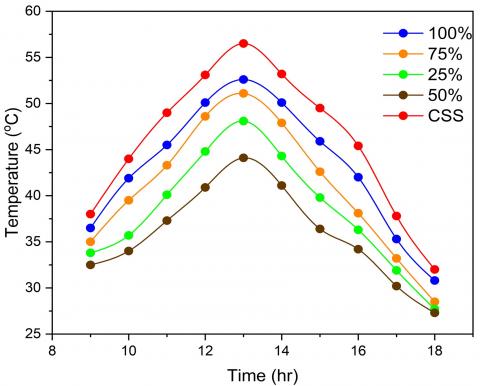
Figure 12 presented illustrates the effect of wick material when occupied 25%, 50%, 75%, 100% from absorber plate on the vapor temperature, tracked over a typical day from 8:00 to 18:00. All the curves have the same trends peaking around midday 13:00, which corresponds to the maximum solar insolation. This suggests that the vapor temperature is highly dependent on solar radiation, which is consistent with the fundamental principles of solar thermal systems. It is evident from the figure that the vapour temperature of MSS (in case of 50% wick) was greater than CSS by 0-9℃, because of the presence of jute which aid to increase the evaporation rate as compared with CSS. As a result, the vapor temperatures of MSS (in case of 50% wick) and CSS are 62.4 and 53.7℃ respectively at 13:00. It should be mentioned that, the temperature of the vapor when using the jute at 50% is higher compared to the vapor temperature when using other ratios. At 50% wick coverage, there is a potential optimal balance where enough surface area is exposed directly to solar radiation to absorb heat efficiently, while simultaneously enough surface area is covered by the wick to utilize the absorbed heat for water evaporation effectively. The wick efficiently disperses water over the heated surface, facilitating efficient evaporation without causing surface flooding. When the wick ratio is at 100%, the absorption surface is excessively shaded or covered by the wick. As a result, it does not allow sufficient solar energy absorption, leading to a decrease in the efficient heat transfer from the absorber to the water. The maximum temperature at 25%, 50%, 75%, 100% coverage were 58.5, 62.4, 57, and 55.7℃ respectively compared with 53.7 for CSS. For case B, incorporating a condenser into a solar still was influence on the vapor temperature positively. It achieves this by remove vapor more efficiently, lowering the highest temperatures and creating a more consistent thermal environment inside the still. This improvement has the potential to increase operational efficiency and overall production, making it an attractive option for improving solar distillation systems. With condenser, the maximum temperature at 25%, 50%, 75%, 100% coverage were 56.4, 59.4, 54.9, and, 53.3℃ respectively compared with 53.4℃ for CSS.
In Figure 13, the CSS had a water temperature that was 0-10℃ higher than that of the MSS because of the absorption surface that floats on the water and covers which is another factor preventing the MSS's basin water from being directly exposed to the sun's rays and lead to decrease its temperature while the CSS relies on direct water heating under the glass cover. Hence, the CSS water temperatures and MSS at (25%, 50%, 75%, 100%) wick ratio were 57, 50.1, 47.1, 53.1, 54.6℃ and respectively at 13:00.
As for case B, there are lowering in the water temperatures for all ratios. So, the water temperatures of the CSS and MSS at (25%, 50%, 75%, 100%) wick ratio were 56.7, 48.1, 44.1, 51.1℃.
(a)
(b)
Figure 12. Variation of vapor temperature with time 25%, 50%, 75%, 100%, (a) without condenser, (b) with condenser
(a)
(b)
Figure 13. Variation of water temperature with time 25%, 50%,75%, 100%, (a) without condenser, (b) with condenser
(a)
(b)
Figure 14. Variation of glass temperature with time 25%, 50%, 75%, 100%, (a) without condenser, (b) with condenser
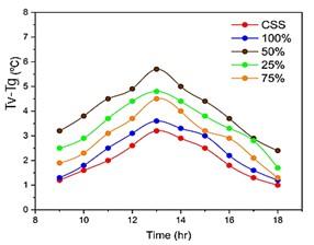
Figure 14 clearly indicates that the glass temperature of the MSS was 3-4℃ higher than that of the CSS. This difference can be attributed to the MSS's higher evaporation rates and faster wick heating in comparison to the CSS. This is occur due to the increase in the temperature of the vapour leads the rate of evaporation also increases due to the greater energy available to the water molecules near the surface. This energy allows them to overcome the atmospheric pressure and change into a gaseous state. When the upward movement of humid-warm air reaches the glass and makes contact with the colder glass cover, it expels its stored heat energy and transforms into a liquid state again. The dissipation of heat at the glass surface results in an increase in the glass's temperature. Consequently, at 13:00, the MSS and CSS had glass temperatures of 59.2 and 51.2℃ respectively when the wick occupied 50% of the absorption surface area (case1), 54℃ at 25%, 56.4℃ at 75%, and 52.7℃ at 100%. Using a condenser, (case 2), leads to reducing the glass temperature because the fans draw vapor from the water and condense it outside, so the vapor pressure inside the distiller decreases. It also leads to making the space dry (low humidity), so the temperatures are relatively lower than before. It became closer to the vapor.
(a)
(b)
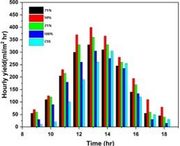
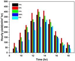
Figure 15. Hourly productivity of different wick ratio (a) without condenser, (b) with condenser
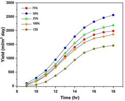
Figure 15 displays solar still hourly production, illustrating the impact of different coverage percentages of wicks on the absorption surface. Productivity has been measured during the hours of 9:00 and 18:00 and is expressed in milliliters per square meter (mL/m²). Compared to the MSS, the distillate production in the CSS is seen to be lower as a result of the presence of wick material and the elevated temperature of the upper plate. It enhances the rate of water evaporation. The low thermal capacity of the wetted wick and capillary action of the wick raise the temperature of the wick surface absorbing more solar radiation. At 13:00, the hourly productivity was maximum. For CSS, the maximum productivity was 260 ml/m2 while for MSS at (25%, 50%, 75%, 100%) wick coverage was 360, 400, 330, 305 mL/m2 respectively without condenser and 400, 425, 370, 250 mL/m2 with condenser. Figure 16 shows the accumulated productivity of MSS (case 1) using 25%, 50%, 75% and 100% were 1795.25, 2225.5, 1945.75 and 1555 mL/m2 day compared with 1340 ml/m2 for CSS. In case of wick, the MSS had an increase in productivity by approximately 33%, 66%, 45% and 16% compared with CSS. In case of wick with external condenser, the improvement of MSS are about 35%, 75%, 50%, and 27% higher than CSS.
(a)
(b)
Figure 16. Accumulated productivity of different wick ratio (a) without condenser, (b) with condenser
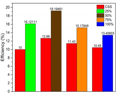
In Figure 17, the daily efficiency of the solar stills was shown for various ratios of wick coverage. The efficiency of CSS stands at 11.49%. With a 75% wick coverage, the efficiency slightly decreases to 14.71% with 19% at 25%. This suggests that maximal wick coverage with a small area of absorption surface exposed does not sufficiently enhance evaporation rates to improve overall efficiency compared to the traditional setup. The full coverage results in the lowest efficiency of 17.48%, likely due to the potential blocking of solar radiation, which is critical for heating the water. 50% Wick Coverage achieves the highest efficiency at 21.14%, indicating an optimal balance between exposure to solar radiation and the enhanced evaporation area provided by the wick. When external condenser used, the daily efficiency of 23.2 at wick ratio 25%, 27.13 at 50%, 19.7 at 75% and 13.48% at 100% as shown in Figure 17(b).
The rate of condensation in the solar still is influenced by the temperature difference between the vapour and the glass. With the presence of an external condenser, because the surface area exposed to condensation has increased, which increase in the heat exchange area between the vapor and the condenser. The glass temperature used in MSS was roughly 0-5℃ greater than the temperature used in CSS. Consequently, the utilisation of the vapour withdrawal technique resulted in a reduction in the temperature of the MSS glass from 0-10℃ to 0-4℃, this has a beneficial impact on the rate of condensation and the performance of the MSS. The temperature of glass for the CSS and MSS with condenser (case 1, 2) was 51.2, 59.3 and 55.1℃ respectively at 13:00. The productivity when using external condenser improved by 35%, 75%, 50%, and 27% as compared with CSS, as shown in Figure 18.
(a)
(b)
Figure 17. Efficiency of different wick ratio (a) without condenser, (b) with condenser
Figure 18. The temperature difference between the interior surface of glass and vapor in case of wick without condenser
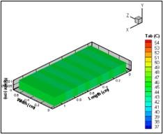
Figure 19 and Figure 20 show the temperature distribution, calculated from the numerical model, of floating absorber surface with wick material installed on it at different hours from the day. It is clearly observed that these temperatures has max intense at (13 pm) then decline during the sunset (16 pm) this is due to the solar flux began to reduces after sunset.
7.2 Numerical simulation results
FORTRAN 90 language is used to build a simulation program for the same experimental cases; the program aims to compare experimental and numerical values; in addition, Navier-Stokes Equations were solved. The results obtained for the water, wick temperature, and hourly yield for conventional solar still and modified solar still with wick coverage 50% from absorber area with and without external condenser are validated with the experimental values in Figures 21-23. A good agreement exists, whereas the maximum deviation varies between 8-10%.
(a)
(b)
(c)
Figure 19. Isotherm contours of absorber a) at 10 am, b) 13 pm, c) 16 pm (case 2)
(a)
(b)
(c)
Figure 20. Isotherm contours of water a) at 10 am, b)13 pm, c) 16 pm (case1)
A- Water temperature
Figure 21. Experimentally and numerically variation of water temperature with time (case 2)
B- Wick temperature
Figure 22. Experimental and numerical variation of wick temperature (50%) with time
C- The productivity
Figure 23. Hourly yield of all cases tested solar still experimentally and numerically
Table 3. The compassion with other researchers
|
Authors |
Still with Improvement |
Enhanced in Productivity |
|
Essa et al. [26] |
Conical absorber with wick materials, as well as external mirrors and an external condenser |
69% with wick 159% with condenser |
|
Omara et al. [27] |
Investigate the performance of vertical rotating wick |
37% |
|
Tuly et al. [28] |
Double slope solar still by using solid rectangular fins, paraffin wax, wick material, and an external condenser |
14% 22% |
|
Modi and Modi [29] |
Small mound of wick material |
18% at 1 cm water depth 22% at 2 cm |
|
Dhindsa et al. [30] |
Floating wicks |
28% |
|
Abdullah et al. [33] |
Corded pyramidal solar stills (CPSS) by using several burlap wicks (jute, cotton, plush, and silk material) and three solar-powered electric heaters |
With wick jute (115%), plush (88%), and silk (60%). With heaters, resulting in a 195% productivity increase. |
|
Present study |
Single slope with different areas of wick with and without condenser |
Wick Without condenser= 66% Wick With condenser= 75% |
7.3 The comparison of results from numerical modeling and experimental results
Figures 19 and 20 present a comparative analysis of the forecasted and observed temperatures for saline water and wick in three scenarios: standard still, modified still with wick only, and modified still with wick and condenser. The expected and measured temperatures of saline water closely matched with a tiny deviation range, whereas the temperature of the wick strongly agreed with the experimental results. Similarly, from Figure 21, the projected and observed yields of the system exhibited comparable patterns, with the model registering greater values in contrast to the empirical outcome. The discrepancy is ascribed to factors such as cloudless conditions, velocity of the wind, and surrounding temperature, as well as the losses incurred throughout the experiment. From the figures, the water, wick temperature, and yield increase due to an increase in solar radiation then it decreases when solar radiation declines after sunset. An analysis of the findings from this study in relation to other similar investigations are listed in Table 3. The performance of the single slope solar still was significantly improved with this improvement, surpassing the results of previous researchers.
This study highlights the innovative application of wick materials and external condensers in solar distillation systems. By optimizing the ratio of wick material and integrating an external condenser, the research presents a highly efficient method for enhancing solar stills' productivity and energy efficiency. The findings provide valuable insights and practical solutions for improving solar water desalination, with implications for addressing water scarcity issues in regions with limited freshwater resources.
CSS efficiency was 11%, while MSS efficiency was 19.19% at 50% wick ratio and 27.13% with an external condenser.
The authors would like to thank the University of Technology-Iraq and to the reviewers for valuable suggestions.
|
Tw |
saline water temperature |
|
${{\text{T}}_{\text{g}}}$ |
glass temperature |
|
${{\text{T}}_{\text{am}}}$ |
ambient temperature |
|
${{\text{T}}_{s}}$ |
sky temperatue |
|
${{\text{I}}_{\text{t}}}$ |
solar radiation |
|
${{\text{A}}_{\text{g}}}$ |
area of glass cover |
|
${{q}_{r}}_{w-g}$ |
radiation heat transfer coefficient from saline water to glass |
|
m• |
mass flow rate |
|
${{\text{q}}_{\text{r},\text{ }\!\!~\!\!\text{ g}-\text{am}}}$ |
radiation heat transfer coefficient from glass to ambient |
|
${{q}_{e,w-g}}$ |
evaporation heat transfer from water to glass |
|
${{q}_{c,w-g}}$ |
convection heat transfer from water to glass |
|
${{\text{ }\!\!\tau\!\!\text{ }}_{\text{g}}}$ |
transmissivity of glass cover |
|
${{q}_{e,w-g}}$ |
evaporation heat transfer from water to glass |
|
${{q}_{c,w-g}}$ |
convection heat transfer from water to glass |
|
Greek symbols |
|
|
k |
thermal conductivity (W/m.k) |
|
ρ |
density (kg/m3) |
|
$\text{ }\!\!\alpha\!\!\text{ }$ |
absorptivity of water |
|
${{\varepsilon }_{w}}$ |
emissivity of water |
|
$\sigma $ |
Stefan-Boltzman constant |
|
Subscript |
|
|
am |
ambient |
|
gin |
the inner surface of the glass cover |
|
gout |
the outer surface of the glass cover |
|
win |
the inlet for solar water heater |
|
wout |
the outlet for solar water heater |
|
b |
basin |
|
w |
water |
|
Abbreviations |
|
|
CSS |
conventional solar still |
|
MSS |
modified solar still |
|
SSSS |
single slope solar still$\text{ }\!\!~\!\!\text{ }$ |
|
D |
mass diffusivity of vapor |
|
C |
concentration of vapor |
|
FEM |
finite element method |
|
FVM |
finite volume method |
|
NSEs |
navier stokes equations |
|
PTC |
parabolic trough collector |
|
PCM |
phase change material |
|
PSS |
pyramid solar still |
|
CPSS |
conventional pyramid solar still |
|
D.C. |
direct current |
|
TES |
thermal energy storage |
|
CV |
control volume |
|
PV |
photovoltaic |
[1] Alawee, W.H., Dhahad, H.A., Mohamed, T.A. (2015). An experimental study on improving the performance of a double slope solar still. In the 7th International Conference on Sustainable Agriculture for Food, Energy and Industry in Regional and Global Context, ICSAFEI.
[2] Chaichan, M.T., Abaas, K.I., Kazem, H.A. (2016). Design and assessment of solar concentrator distillating system using phase change materials (PCM) suitable for desertic weathers. Desalination and Water Treatment, 57(32): 14897-14907. https://doi.org/10.1080/19443994.2015.1069221
[3] Ahmed, S.T., Ali, H.H.M. (2020). Experimental investigation of new design of solar water distillation coupled with flat plate solar water collector. The Iraqi Journal for Mechanical and Materials Engineering, 20(3): 193-207. https://doi.org/10.32852/iqjfmme.v20i3.512
[4] Alawee, W.H., A Hammoodi, K., Dhahad, H.A., Omara, Z.M., Essa, F.A., Abdullah, A.S., Amro, M.I. (2023). Effects of magnetic field on the performance of solar distillers: A review study. Engineering and Technology Journal, 41(1): 121-131. https://doi.org/10.30684/etj.2022.134576.1240
[5] Abbas, H., Jalil, J.M., Ahmed, S.T. (2021). Experimental investigation of the optimal location of PCM capsules in a hollow brick wall. Engineering and Technology Journal, 39(5): 846-858. https://doi.org/10.30684/etj.v39i5a.1980
[6] Shalaby, S.M., El-Bialy, E., El-Sebaii, A.A. (2016). An experimental investigation of a v-corrugated absorber single-basin solar still using PCM. Desalination, 398: 247-255. https://doi.org/10.37896/jxu14.4/310
[7] Abed, A.H., Hoshi, H.A., Jabal, M.H. (2021). Experimental investigation of modified solar still coupled with high-frequency ultrasonic vaporizer and phase change material capsules. Case Studies in Thermal Engineering, 28: 101531. https://doi.org/10.1016/j.desal.2016.07.042
[8] Ghandourah, E., Panchal, H., Fallatah, O., Ahmed, H.M., Moustafa, E.B., Elsheikh, A.H. (2022). Performance enhancement and economic analysis of pyramid solar still with corrugated absorber plate and conventional solar still: A case study. Case Studies in Thermal Engineering, 35: 101966. https://doi.org/10.1016/j.csite.2021.101531
[9] Kabeel, A.E., Harby, K., Abdelgaied, M., Eisa, A. (2020). Performance of the modified tubular solar still integrated with cylindrical parabolic concentrators. Solar Energy, 204: 181-189. https://doi.org/10.1016/j.csite.2022.101966
[10] Yadav, Y.P. (1991). Performance analysis of a solar still coupled to a heat exchanger. Desalination, 82(1-3): 243. https://doi.org/10.1016/0011-9164(91)85188-Z
[11] Omara, Z.M., Alawee, W.H., Mohammed, S.A., Dhahad, H.A., Abdullah, A.S., Essa, F.A. (2022). Experimental study on the performance of pyramid solar still with novel convex and dish absorbers and wick materials. Journal of Cleaner Production, 373: 133835. https://doi.org/10.1016/0011-9164(93)80052-o
[12] Taamneh, Y., Taamneh, M.M. (2012). Performance of pyramid-shaped solar still: Experimental study. Desalination, 291: 65-68. https://doi.org/10.1016/j.desal.2012.01.026
[13] Younes, M.M., Abdullah, A.S., Essa, F.A., Omara, Z.M., Amro, M.I. (2021). Enhancing the wick solar still performance using half barrel and corrugated absorbers. Process Safety and Environmental Protection, 150: 440-452.
[14] Valsaraj, P. (2002). An experimental study on solar distillation in a single slope basin still by surface heating the water mass. Renewable Energy, 25(4): 607-612. https://doi.org/10.1016/s0960-1481(01)00094-5
[15] Din, S.I.U., Abd Hamid, A.S., Ibrahim, A., Nawab, F., Sopian, K., Fazlizan, A., Ishak, A. (2023). Performance analysis of a novel photovoltaic thermal PVT double pass solar air heater with cylindrical PCM capsules using CFD. International Journal of Renewable Energy Research (IJRER), 13(3): 1418-1430. https://doi.org/10.20508/ijrer.v13i3.14136.g8814
[16] Omara, Z.M., Kabeel, A.E., Essa, F.A. (2015). Effect of using nanofluids and providing vacuum on the yield of corrugated wick solar still. Energy Conversion and Management, 103: 965-972. https://doi.org/10.1016/j.enconman.2015.07.035
[17] Torchia-Núñez, J.C., Cervantes-de-Gortari, J., Porta-Gándara, M.A. (2014). Thermodynamics of a shallow solar still. Energy and Power Engineering, 2014. https://doi.org/10.4236/epe.2014.69022
[18] Xiao, G., Wang, X., Ni, M., Wang, F., Zhu, W., Luo, Z., Cen, K. (2013). A review on solar stills for brine desalination. Applied Energy, 103: 642-652. https://doi.org/10.1016/j.apenergy.2012.10.029
[19] Sivakumar, V., Sundaram, E.G. (2013). Improvement techniques of solar still efficiency: A review. Renewable and Sustainable Energy Reviews, 28: 246-264. https://doi.org/10.1016/j.rser.2013.07.037
[20] Fale, S.M., Dogra, S. (2023). An experimental investigation on an inclined solar distiller with a stepped-corrugated absorber and evacuated tubes. International Journal of Renewable Energy Research, 13(3): 1311-1331. https://doi.org/10.20508/ijrer.v13i3.14165.g8803
[21] Omara, Z.M., Hamed, M.H., Kabeel, A.E. (2011). Performance of finned and corrugated absorbers solar stills under Egyptian conditions. Desalination, 277(1-3): 281-287. https://doi.org/10.1016/j.desal.2011.04.042
[22] Khafaji, H.Q.A., Abdul Wahhab, H.A., Al-Maliki, W.A.K., Alobaid, F., Epple, B. (2022). Energy and exergy analysis for single slope passive solar still with different water depth located in Baghdad center. Applied Sciences, 12(17): 8561. https://doi.org/10.3390/app12178561
[23] Aboud, G.A., Hussein, H.A., Numan, A.H. (2022). Effect of temperature and humidity factors on water production using solar energy with smart controlling. Engineering and Technology Journal, 40(1): 241–248. https://doi.org/10.30684/etj.v40i1.2282
[24] Jalil, J.M., Mahdi, H.S., Allawy, A.S. (2022). Cooling performance investigation of PCM integrated into heat sink with nanoparticles addition. Journal of Energy Storage, 55: 105466. https://doi.org/10.1016/j.est.2022.105466
[25] Abbas, H.M., Jalil, J.M., Ahmed, S.T. (2021). Experimental and numerical investigation of PCM capsules as insulation materials inserted into a hollow brick wall. Energy and Buildings, 246: 111127. https://doi.org/10.1016/j.enbuild.2021.111127
[26] Essa, F.A., Alawee, W.H., Abdullah, A.S., Aljaghtham, M., Mohammed, S.A., Dhahad, H.A., Majdi, A., Omara, Z.M. (2022). Augmenting the performance of pyramid distiller via conical absorbing surface, reflectors, condenser, and thermal storing material. Journal of Energy Storage, 55: 105597. https://doi.org/10.1016/j.est.2022.105597
[27] Omara, Z.M., Abdullah, A.S., Essa, F.A., Younes, M.M. (2021). Performance evaluation of a vertical rotating wick solar still. Process Safety and Environmental Protection, 148: 796-804. https://doi.org/10.1016/j.psep.2021.02.004
[28] Tuly, S.S., Rahman, M.S., Sarker, M.R.I., Beg, R.A. (2021). Combined influence of fin, phase change material, wick, and external condenser on the thermal performance of a double slope solar still. Journal of Cleaner Production, 287: 125458. https://doi.org/10.1016/j.jclepro.2020.125458
[29] Modi, K.V., Modi, J.G. (2019). Performance of single-slope double-basin solar stills with small pile of wick materials. Applied Thermal Engineering, 149: 723-730. https://doi.org/10.1016/j.applthermaleng.2018.12.071
[30] Dhindsa, G.S. (2021). Performance enhancement of basin solar still using paraffin wax and floating wicks in the basin. Materials Today: Proceedings, 37(Part 2): 3310-3316. https://doi.org/10.1016/j.matpr.2020.09.121
[31] Najaf, F., Aslan, S.R. (2024). Enhancing water purification in solar stills through incorporation of renewable energy technology: An experimental study on the efficiency and cooling mechanisms - a review. International Journal of Heat Technology, 42(1): 101. https://doi.org/10.18280/ijht.420111
[32] Hammoodi, K.A., Dhahad, H.A., Alawee, W.H., Omara, Z.M. (2023). Enhancement of pyramid solar still productivity through wick material and reflective applications in Iraqi conditions. Mathematical Modelling of Engineering Problems, 10(5): 1548. https://doi.org/10.18280/mmep.100506
[33] Abdullah, A.S., Alawee, W.H., Mohammed, S.A., Majdi, A., Omara, Z.M., Essa, F.A. (2023). Increasing the productivity of modified cords pyramid solar still using electric heater and various wick materials. Process Safety and Environmental Protection, 169: 169-176. https://doi.org/10.1016/j.psep.2022.11.016
[34] Al-Shamkhee, D.M.H., Abed, Q.A. (2016). Theoretical study the effect of insulation of water basin on the productivity of tubular solar still. In 5th International Conference on Thermal Equipment, Renewable Energy and Rural Development, pp. 29-34. https://www.academia.edu/33090553/THEORETICAL_STUDY_THE_EFFECT_OF_INSULATION_OF_WATER_BASIN_ON_THE_PRODUCTIVITY_OF_TUBULAR_SOLAR_STILL.
[35] Multiphysics, C. (2021). Fluid governing equations. What are the Navier–Stokes Equations.
[36] Kabeel, A.E., Khalil, A., Omara, Z.M., Younes, M.M. (2012). Theoretical and experimental parametric study of modified stepped solar still. Desalination, 289: 12-20. https://doi.org/10.1016/j.desal.2011.12.023
[37] Kabeel, A.E., Taamneh, Y., Sathyamurthy, R., Naveen Kumar, P., Manokar, A.M., Arunkumar, T. (2019). Experimental study on conventional solar still integrated with inclined solar still under different water depth. Heat Transfer Research, 48(1): 100-114. https://doi.org/10.1002/htj.21370
[38] Velmurugan, V., Kumaran, S.S., Prabhu, N.V., Srithar, K. (2008). Productivity enhancement of stepped solar still: Performance analysis. Thermal Science, 12(3): 153-163. https://doi.org/10.2298/tsci0803153v
[39] Sonker, V.K., Chakraborty, J.P., Sarkar, A., Singh, R.K. (2019). Solar distillation using three different phase change materials stored in a copper cylinder. Energy Reports, 5: 1532-1542. https://doi.org/10.1016/j.egyr.2019.10.023
[40] Tiwari, G.N., Sahota, L. (2017). Advanced Solar-Distillation Systems: Basic Principles, Thermal Modeling, and Its Application. Springer Singapore. https://doi.org/10.1007/978-981-10-4672-8
[41] Bejan, A. (2013). Convection Heat Transfer. John Wiley & Sons.
[42] Bao, N.T. (2019). The mathematical model of basin-type solar distillation systems. Distillation – Modelling, Simulation and Optimization. https://doi.org/10.5772/inte-chopen.83228
[43] Nwosu, E.C., Nwaji, G.N., Ononogbo, C., Ofong, I., Nwadinobi, P.C., Ogueke, N.V., Anyanwu, E.E. (2022). Numerical and experimental study of a single-slope double-effect solar still integrated with paraffin wax. Energy Nexus, 8: 100155. https://doi.org/10.1016/j.nexus.2022.100155
[44] Essa, F.A., Abdullah, A.S., Omara, Z.M. (2020). Rotating discs solar still: New mechanism of desalination. Journal of Cleaner Production, 275: 123200. https://doi.org/10.1016/j.jclepro.2020.123200
[45] Agrawal, A., Rana, R.S. (2019). Theoretical and experimental performance evaluation of single-slope single-basin solar still with multiple V-shaped floating wicks. Heliyon, 5(4): E01525. https://doi.org/10.1016/j.heliyon.2019.e01525