Alyaa Qasim Najm*![]() | Saadoon Fahad Dakhil | Ahmed Qasim Mohammed
| Saadoon Fahad Dakhil | Ahmed Qasim Mohammed
© 2024 The authors. This article is published by IIETA and is licensed under the CC BY 4.0 license (http://creativecommons.org/licenses/by/4.0/).
OPEN ACCESS
The aim of the present work is to investigate the performance indication and flow of a counter heat device using different baffle configurations numerically. This research illustrates the consequence of segmental stumps and wavy cross-section stumps with varying wave numbers and amplitude. The governing equations of energy and Navier-Stokes equations were solved using the Computational Fluid Dynamics (CFD) software package FLUENT 22R1, employing the finite volume method. The SIMPLE algorithm with second-order upwind discretization for the convection term was used for velocity and pressure calculations. Different cold water rates of flow (2, 4, 6, and 8 L/min) at 23℃ through shell and Constand hot water flow rate at 1 LPM at 50℃ were analysed for their effect on heat transfer efficiency. The heat exchanger's thermal performance was comparing its duty with various baffle configurations to its performance without baffle. The research results indicate that installing baffles increased the heat exchanger's effectiveness (ε)., with the enhancement ratio (ε/εNE) reaching 1.2 and 1.23 for segmental and wavy baffles respectively compared to no baffle. On the other hand, the overall heat transfer coefficient (Uo) showed an improvement with baffles, achieving a performance increase of up to 1.38 at 8 LPM for Wavy baffles with wave number and amplitude (15 and 3 mm) respectively. The pressure drop in the system increased to 406 Pa at wavy baffles (15 and 3 mm) of 6 LPM. The maximum amount of exergy destruction being approximately 0.29 at 8 LPM for segmental. The results providing insights into optimal baffle design for specific applications.
baffles, wavy cross section, segmental, CFD, heat exchanger, fluent
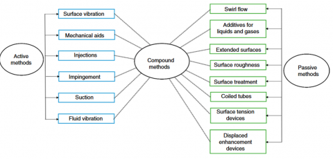
For industrial processes that need to manage heat, heat exchangers are a must. One of the most crucial variables impacting pressure drop and enhancing the flow of heat in a shell and tube heat exchanger is the design of its baffles. As observed in Figure 1, multiple methods have been developed over time that enhance heat transfer rates and performance while optimizing the weight, size, and cost of heat exchangers. These methods classified into active, passive, and compound techniques [1]. In the active method, an external supplement of energy is required. However, passive methods renovate the heat transfer area [2]. Shell and tube heat exchanger (STHE) is widely used in petro-chemical industry, power generation, energy conservation, and manufacturing industry. The baffle member plays an important role in STHE, and it supports tube bundle and also equally distribute the fluid in the shell side. When segmental baffles are used in STHE which have many disadvantages. Flow stagnation allows dead zones to form at the corners where the shell wall and baffle meet, which is the cause of the low heat transfer efficiency. Significantly less pressure occurs for the same heat load due to this stagnation, which requires greater pumping power. Further influencing the overall heat transfer effectiveness is the orientation of the tubes, which influences the annular surface area associated with by the fluid [3]. Extensive studies of shell and tube heat exchangers utilizing various baffle designs had been done in the past. By examining the shell-side flow with and without baffles employing CFD analysis by Anjineyulu and Mohanty [4] simulations, it can be seen to see that inserting baffles significantly improves the flow of heat. The result present that overall heat transfer coefficient increases from 60 to 85% with decrease in baffle cut from 41.5 to 22.5%. Investigated by Dineshbabu et al. [5] study the enhancing shell and tube heat exchangers' performance by analyzing various baffle configurations, such as single segment, double segment, single helical, NTIW, propeller type, and spiral baffles. Using HTRI and CFD, it finds that single helical 15° and double segmental baffles significantly improve heat transfer and efficiency compared to other configurations. Using SolidWorks Flow Simulation, Uosofvand and Abbasian Arani [6] examined a new hybrid segmental-helical baffles shell-and-tube heat exchanger (HSHB-STHX) with different ribbed tubes. It provides the best baffle arrangement and rib shape by comparing efficiency assessment, heat transfer to pressure drop (Q/∆p), performance evaluation criteria (PEC), and Nusselt number to pressure drop (Nu/∆p). The best model, based upon the results, is the HSHB-STHX, that have rectangular ribbed tubes and six segmental baffles oriented at a 90° angle. Its PEC is 41% more than that of standard models. Different baffle types and orientations have an influence on thermal performance and pressure drop when evaluating shell and tube heat exchangers. Complex baffles increase pumping power and pressure loss, which lowers efficiency even while they increase heat transfer. Numerical simulations result show that helical baffles minimize pressure drop by eliminating dead zones, enhancing heat transfer and system efficiency compared to single and double segmental baffles [7]. Petinrin and Dare [8] studied the performance of shell-and-tube heat exchangers using single-segmental baffles and concave-cut baffles (10%, 15%, and 20%). They tested different fluids on the shell side, including engine oil, water, and air. The study found that while the k-ε and RNG k-ε models provided similar results, the heat exchangers with concave-cut baffles had higher pressure drops and lower performance factors than those with single-segmental baffles. Additionally, concave-cut baffles resulted in lower shell-side heat transfer coefficients, leading to no significant performance improvement over segmental baffles at the same pressure drop. Wang et al. [9] used computational fluid dynamics to study heat transfer and mixing in shell-and-tube heat exchangers with a novel X-type baffle configuration. They found that a smaller length-diameter ratio improves mixing and heat transfer but raises the pressure drop. Increasing the crossbar number enhances overall performance by reducing both the heat transfer coefficient and pressure drop. Compared to the Sulzer mixer reactor (SMR), the X-type baffle heat exchanger offers equivalent or better heat transfer, especially at higher Reynolds numbers, and provides a narrower residence time distribution, improving process control for highly viscous fluids. Prasanthi [10] studied a shell and tube heat exchanger with helical baffles, finding that increasing the helix angle improved the overall heat transfer coefficient while reducing the pressure drop. A 6-degree helix angle offered better heat transfer and lower pumping costs compared to an 18-degree angle. Another study by You et al. [11] introduces a numerical model using porosity and permeability to evaluate shell-side thermal hydraulic performance. Applied to a shell-and-tube heat exchanger (STHX) with flower baffles, the model shows reasonable accuracy with a maximum relative deviation of 15% compared to test data. The results effectively illustrate velocity, temperature fields, and convective heat transfer distribution, demonstrating the model's efficiency for thermal hydraulic analysis. Numerical investigates the impact of a "wavy inner tube" design on heat transfer in a double-pipe heat exchanger using ANSYS Fluent by Hasgul and Cakmak [12]. The wavy tube induces turbulence, enhancing heat transfer. Simulations were conducted for Reynolds numbers between 2700 and 5300, and results were validated against experimental data. The highest heat transfer, a 270% increase over a straight tube, was achieved with a 16-wave tube under counter flow conditions. Wang et al. [13] examined cross wavy primary surface heat exchangers, ideal for microturbines, and introduced triangular, rectangular, and circular cross wavy channel designs. Their simulations showed that triangular channels have the highest efficiency, rectangular channels achieve the largest heat transfer, and circular channels have the smallest irreversible loss. They also developed correlations for the Nusselt number and friction factor, with validation errors of 2.71% and 7.85%, respectively. Ahmed et al. [14] introduced a wavy-tape insert for enhancing heat transfer in pipes. Computational fluid dynamics simulations showed that the insert can double heat transfer by inducing swirl flow and vortex pairs. Parametric analysis revealed that increasing tape width improves thermal performance, while higher Reynolds numbers and tape amplitude reduce it. The optimized design offers significant potential for high-performance heat exchangers. Qu et al. [15] analyzed the thermal-hydraulic performance of sinusoidal channels with varying inclination angles and amplitudes using CFD simulations. They found that models with smaller inlet amplitudes and more periods per group improved heat transfer, with a 36.37% increase in performance for six-period models. Hot fluid performance improved with more variations, while cold fluid performance declined.
The focus of this study is to apply CFD simulations to investigate the thermal and hydraulic performance of two different baffle configurations: Segmental baffles and wavy cross-section baffles. A lot of research has been done on this behaviour mainly looking at baffles. Our study takes a path by introducing a new method that includes optimal wavy cross sections called "wavy baffles.
Figure 1. Types of heat transfer enhancement for active, passive, and compound methods [16]
2.1 CFD simulation
The shell-and-tube heat exchanger's heat transfer mechanisms will be simulated employing CFD simulations and ANSYS Fluent. For 3D pressure and velocity processing, the SIMPLE method with a second-order upwind discretization for the convection term was used. Figure 2 is a schematic depiction of a shell and tube heat exchanger that uses convection heat transfer and shows the computational domain that is used for analysis. Table 1 illustrates the design parameters for the heat exchanger, that is modeled with 18 tubes and 3 baffles of different geometry. The hot water flows through the tubes at a flow rate of 1 L/min and inlet temperature of 50℃, while the cold water flows through the shell at varying flow rates (2, 4, 6, and 8 L/min) with inlet temperature of 23℃. Fluid properties were held constant as detailed in Table 2. The segmental baffles were formed by splitting them at the specified baffle cut height and relocating them to the positions shown in Figure 2(b). Meanwhile, the wavy cross-section was achieved by superimposing a sine wave, characterized by an amplitude A and a number N of waves, as illustrated in Figure 2(c). Table 3 displays the amplitude and number of these waves. The analytical equation defining the wavy cross-section is presented in reference [17].
r(θ) = R + Ar * sin(Nθ)
Table 1. Design parameters and fixed geometric parameters
|
No. |
Unit |
Value |
|
1 |
Large Shell diameter mm |
120 |
|
2 |
Small Shell diameter mm |
110 |
|
3 |
Outer Tube diameter mm |
6.3 |
|
4 |
Inner Tube diameter mm |
5 |
|
5 |
Tubes Number of |
18 |
|
6 |
Shell length mm |
490 |
|
7 |
Diameter of baffles mm |
110 |
|
8 |
Tube length mm |
590 |
|
9 |
Number of baffles |
3 |
|
10 |
Thickness of baffles mm |
10 |
|
11 |
the material of tube |
copper |
|
12 |
the material of Baffle |
pvc |
|
13 |
the material of shell |
plexiglass |
|
14 |
Fluid in tube |
Hot fluid |
|
15 |
Fluid in Shell |
Cold fluid |
Table 2. Fluid properties
|
Properties |
Density (Kg/m3) |
Thermal Conductivity (W/m-k) |
Specific Heat (J/kg-k) |
Viscosity (kg/m-s) |
|
Water at 50℃ |
998 |
0.641 |
4182 |
0.000547 |
|
Water at 23℃ |
997.58 |
0.61 |
4180.8 |
0.000891 |
Table 3. The amplitude of waves and the number of waves used to create wavy baffles
|
Amplitude (mm) |
Number of Waves |
|
3, 5, 10 |
10 |
|
3, 5, 10 |
15 |
The current model solution is predicated on the following premises:
•There is a regular, laminar, three-dimensional incompressible flow; the fluid is Newtonian.
•Water has constant characteristics and is the working fluid.
•Internal heat generation is excluded from the energy equation, and the viscous dissipation term and radiation were neglected.
All solid boundaries are to be rigid no-slip condition.
Figure 2. Schematic drawing of shell and tube H.E
2.2 Mesh generation
The mesh for the heat exchanger model was generated using ANSYS Meshing. Tetrahedral meshes were utilized for most of the geometry to balance accuracy with computational efficiency. A finer mesh featuring a higher element density was employed near the tube walls and baffles to precisely capture boundary layer effects. After various experiments with different mesh sizes, an optimal configuration was achieved with a total cell count of 8,000,000. The mesh comprises 1,993,450 nodes and 8,087,487 elements, with an average element quality of 0.82, a maximum cell skewness of 0.84, and an aspect ratio of 14.98. Figure 3 illustrates a vertical cut-plane of the generated mesh, highlighting areas with the maximum skewness value of 0.84.
Figure 3. Schematic of geometry and grid network
2.3 Governing equations
Governing equation are presented with three dimensional in cylindrical are based on the following equations:
Continuity equation:
$\frac{\partial u_r}{\partial r}+\frac{u_r}{r}+\frac{1}{r} \frac{\partial u_\theta}{\partial \theta}+\frac{\partial u_z}{\partial z}=0$ (1)
$\theta$ - Direction momentum equation:
$\begin{gathered}u_r \frac{\partial u_\theta}{\partial r}+\frac{u_\theta}{r} \frac{\partial u_\theta}{\partial \theta}+\frac{u_\theta u_r}{r}+u_z \frac{\partial u_\theta}{\partial z} =v\left(\frac{\partial^2 u_\theta}{\partial r^2}+\frac{1}{r} \frac{\partial u_\theta}{\partial r}-\frac{u_\theta}{r^2}+\frac{1}{r^2} \frac{\partial^2 u_\theta}{\partial \theta^2}+\frac{2}{r^2} \frac{\partial u_r}{\partial \theta}\right. \left.+\frac{\partial^2 u_\theta}{\partial z^2}\right)-\frac{1}{r \rho} \frac{\partial p}{\partial \theta}\end{gathered}$ (2)
r - Direction momentum equation:
$\begin{gathered}u_r \frac{\partial u_r}{\partial r}+\frac{u_\theta}{r} \frac{\partial u_r}{\partial \theta}-\frac{u_\theta}{r}+u_z \frac{\partial u_r}{\partial z} =v\left(\frac{\partial^2 u_r}{\partial r^2}+\frac{1}{r} \frac{\partial u_r}{\partial r}-\frac{u_r}{r^2}+\frac{1}{r^2} \frac{\partial^2 u_r}{\partial \theta^2}-\frac{2}{r^2} \frac{\partial u_\theta}{\partial \theta}\right. \left.+\frac{\partial^2 u_r}{\partial z^2}\right)-\frac{1}{\rho} \frac{\partial p}{\partial r}\end{gathered}$ (3)
Z - Direction momentum equation:
$\begin{gathered}u_r \frac{\partial u_z}{\partial r}+\frac{u_\theta}{r} \frac{\partial u_z}{\partial \theta}+u_z \frac{\partial u_z}{\partial z} =v\left(\frac{\partial^2 u_z}{\partial r^2}+\frac{1}{r} \frac{\partial u_z}{\partial r}+\frac{1}{r^2} \frac{\partial^2 u_z}{\partial \theta^2}+\frac{\partial^2 u_r}{\partial z^2}\right)-\frac{1}{\rho} \frac{\partial p}{\partial z}\end{gathered}$ (4)
Energy equation:
•For fluid region:
$\begin{aligned} & u_r \frac{\partial T_f}{\partial r}+\frac{u_\theta}{r} \frac{\partial T_f}{\partial \theta}+u_z \frac{\partial T_f}{\partial z} = \alpha\left(\frac{1}{r} \frac{\partial^2 T_f}{\partial r^2}+\frac{1}{r^2} \frac{\partial^2 T_f}{\partial \theta^2}+\frac{\partial^2 T_f}{\partial z^2}\right)\end{aligned}$ (5)
•For solid region:
$\frac{\partial^2 T_s}{\partial r^2}+\frac{1}{r} \frac{\partial T_s}{\partial r}+\frac{1}{r^2} \frac{\partial^2 T_s}{\partial \theta^2}+\frac{\partial^2 T_s}{\partial z^2}=0$ (6)
2.4 Boundary conditions
Temperatures and mass flow rates are specified as boundary conditions at the input nozzles close to the shell and tube system. A gauge pressure of zero is set at the nozzle and tube outlets to assess the relative pressure drop across these points. Calculations for momentum and mass utilize the average static pressure. The system enforces no-slip conditions on the walls, and areas with zero heat flux include the shell’s outer cover and the tube side covers, as detailed in Table 4.
The model distinguishes between solid and fluid volumes. Fluid domains, where the fluid flows, encompass the inner sections of the tubes and the shell. Areas enclosed by baffles, along with the material thickness of the tubes and shell, are classified as solid domains. There are fluid-solid interfaces between the fluid in the shell and the solid baffles, as well as between the fluid inside the tubes and the solid tube material. Solid-solid interfaces occur between the solid tubes and solid baffles, as well as between the solid baffles and the shell structure.
Table 4. Boundary conditions for validation
|
Parameter |
Shell |
Tube |
|
Mass flow rate |
2, 4 and 6 LPM |
1 LPM |
|
Inlet temperature |
50℃ |
23℃ |
|
Outlet- Pressure |
Qutlet pressure is zero, Pout=0 |
Outlet pressure is zero, Pout, h=0 |
|
No slip condition |
No-slip and adiabatic wall No heat flux |
Coupled |
2.5 Parameter definitions
The ratio of the actual heat transfer takes place within the system to the maximum heat transfer that could potentially be achieved is known as heat exchanger effectiveness, and it is a performance parameter [18].
$\varepsilon_f=\frac{q_{\text {act }}^{\prime \prime}}{q_{\max }^{\prime \prime}}$ (7)
where, the product of the highest temperature differential and the lowest heat capacity yields the maximum heat transfer, as:
$q_{\max }^{\prime \prime}=C\left(T_{h, i}-T_{c, i}\right)_{\min }$ (8)
And the actual amount of heat lost by hot fluid or gained by the cold fluid is expressed as:
$q_{a c t}^{\prime \prime}=C_h\left(T_{h, i}-T_{\mathrm{ho}}\right)=C_c\left(T_{\mathrm{co}}-T_{c, i}\right)$ (9)
$C_h=\dot{m}_h C_{p, h}, C_c=\dot{m}_c C_{p, c}$ (10)
$\varepsilon_f=\frac{\mathrm{C}_h\left(\mathrm{~T}_{h i}-\mathrm{T}_{h o}\right)}{\mathrm{C}_{\min }\left(\mathrm{T}_{h i}-\mathrm{T}_{c i}\right)}=\frac{\mathrm{C}_c\left(\mathrm{~T}_{c o}-\mathrm{T}_{c i}\right)}{\mathrm{C}_{\min }\left(\mathrm{T}_{h i}-\mathrm{T}_{c i}\right)}$ (11)
The following equation can be utilized to calculate the overall heat transfer coefficient [6].
$U=\frac{Q_{ {avg }}}{A_0 \cdot \Delta T_{L M T D}}$ (12)
where, $Q_{a v g}$, A0 and ∆TLMTD represent the heat transfer rate, surface area of heat transfer, and the log-mean temperature difference, respectively [6].
$A_0=\pi d_o L N_t$ (13)
$Q_{a v}=1 / 2\left(Q_h+Q_c\right)$ (14)
$\Delta T_{\mathrm{LMTD}}=\frac{\left(T_{h, i}-T_{c, o}\right)-\left(T_{h, o}-T_{c, i}\right)}{\ln \left(\frac{T_{h, i}-T_{c, o}}{T_{h, o}-T_{c, i}}\right)}$ (15)
The pressure drops across the shell and tube calculated as the difference between the inlet and outlet pressure. Friction coefficient (f) for tube is described on the basis wall friction forces per inertia forces and it is represented by following equation:
$\Delta p=P_{\text {in }}-P_o$ (16)
The exergy loss and the dimensionless exergy loss has been calculated using following equation [19]:
$E_h=T_e\left(\dot{m}_h \times c_p \times \ln \frac{T_{h o}}{T_{h i}}\right)$ (17)
$E_c=T_e\left(\dot{m}_c \times c_p \times \ln \frac{T_{c o}}{T_{c i}}\right)$ (18)
$E=E_h+E_c$ (19)
$e=\frac{E}{T_{e C_{\min }}}$ (20)
Cmin=Min{Ch and Cc} (21)
In the current study, counter flow SHTEs with and without baffles were examined. Hot water was passed via the tubes from geysers, while cold water circulated throughout shell side. Mass flow rate of the inlet hot fluid is maintained constant, i.e. 1 LPM (0.01667Kg/s), while the mass flow rate of inlet cold fluid varies between 2 LPM, 4 LPM, 6 LPM, and 8 LPM, i.e. (0.0333 kg/s, 0.0665 kg/s, 0.0998 kg/s, 0.133 kg/s). The parameters are used to determine the fluctuation of Uo, ΔP and effectiveness (ɛ) for the shell side of the heat exchanger with wavy and segmental types baffles.
3.1 Shell-side flow field
Figure 4 exhibits the water flow path lines at 0.0333 kg/s on the shell-sides of the heat exchangers. It is clear that the baffles' layout influences how the fluid meanders from the shell-inlet duct to the output duct. Unlike wavy STHE, which gives across the baffle cut, segmental STHE flows more concentrated at the center of the cut. Also, because the shell's flow area is bigger than that of the shell ducts, the fluid velocity inside the shell is decreased. A good interaction between the fluid on the shell's side and the tube's outer surfaces is produced by the combined fluid mixing caused by the cross- and counter-flows in the shell, which enhances the heat transfer between the working fluids.
Figure 4. Velocity vector for shell and tube with segmental and wavy baffles at centre plane Nb=3 and Qh=1 LPM
3.2 Temperature distribution
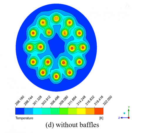
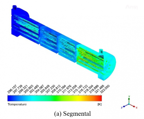
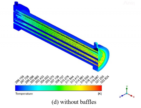
Both Figures 5 and 6 show the heat exchangers' shell-side temperature distributions. It is apparent that as the fluid moves from the fluid entrance point to the shell's outlet, its temperature drops. In addition, it has been noted that a higher drop in fluid temperature was experienced across the tube bundles because the cross-flow tubes' larger surface area allowed them to conduct heat better than the tubes in the baffle windows. Regarding the two heat exchangers, this observation is equal. The fluid for the segmental baffle was heated rapidly by the tube bundle in specific regions (along the shell side), but the heat could not be transferred quickly. Figure 6(b and c)'s wavy baffle enhances the flow distribution in exchange. As such, there is more consistency in the temperature and heat exchange. The temperature contour displays these benefits when compared to the wavy baffle and the absence of a baffle, based on the acquired result.
Figure 5. Temperature distribution contours for Baffles at Qh=1 LPM and Qc=2 LPM in Y-X plane at L=11 cm
Figure 6. Temperature distribution contours for various types of STHX shell and tube (a) segmental (b) wavy baffles at Ar=5 mm, (c) wavy baffles at Ar=7 mm Nb=3, Nw= 10, (d) without baffles, at Qh=1 LPM and Qc=2 LPM
3.3 Effectiveness
Figure 7 illustrates the effectiveness of the heat exchanger for different baffle configurations at various shell side flow rates (Qs). Effectiveness is a measure of the efficiency of the heat exchanger in transferring heat between the fluids. The effectiveness of configurations no Baffles increases with higher cold water flow rates but remains the lowest among the three configurations. This is due to the lack of turbulence within the heat exchanger, resulting in lower heat transfer efficiency. The segmental baffle shows the highest effectiveness across most flow rates, reaching close to 0.73 at higher flow rates 8 LPM. The zigzag path imposed by the segmental baffle increases the contact time between the fluids, leading to higher effectiveness. The effectiveness of wavy baffles (Nw=10, Ar=3 mm) shows a moderate effectiveness, generally around 0.55 to 0.725 is better than the no baffles configuration but lower than that of segmental baffles. The lower amplitude (3 mm) creates moderate turbulence and mixing, which improves effectiveness. Wavy Baffles (Nw=10, Ar=5 mm and Ar=7 mm) Both configurations demonstrate similar effectiveness, slightly less than the 3 mm amplitude. Wavy Baffles (Nw=15, Ar=3 mm) shows a relatively high effectiveness, close to that of the segmental baffle. The higher number of waves (Nw=15) enhances fluid mixing and turbulence more effectively than lower wave numbers. The optimal amplitude of 3mm helps maintain a balance between increasing turbulence and managing pressure drops.
Figure 7. Variation of effectiveness with Qs for different baffles Configuration, and without baffles, number of waves=10, amplitude=5 mm, constant tube side (hot water) flow rate=1 LPM (0.0166) and ΔT=27℃
Figure 8. The enhancement ratio (ε/εNE) at the heat exchanger for different baffles Configuration, and without baffles, at wave number waves (15, 10), amplitude (3, 5 and 7) mm, constant tube side (hot water) flow rate=1 LPM (0.0166) and ΔT=27℃
Figure 8 presents the enhancement ratio of the effectiveness (ε/εNE) for different baffles Configuration, and without baffles for different shell side flow rates, with constant value of hot volume flow rate. According to the data, the effectiveness enhancement ratio reaches 1.23 at 8 LPM (Nw=15 and Ar=3 mm) compare to 1.2 at segmental baffles. Additionally, there is an increase in the enhancement ratio of the effectiveness from 1.26 to 1.2 when comparing with concentration under the same conditions. This analysis underscores the importance of choosing appropriate baffle configurations to optimize the heat exchanger's effectiveness, considering factors like turbulence, mixing, and pressure drop.
3.4 Over all coefficient of heat transfer
Figure 9 explains the variation of Overall Heat transfer for different baffle types at varying shell volumetric flow rates (Qs), and without baffles. In this study, the number of waves is 10, 15 the amplitude is (3, 5 and 6) mm, the tube side (hot water) flow rate is constant at 1 LPM (0.0166 L/s). The overall heat transfer coefficient increases significantly with the shell side flow rate. Segmental baffles create a more tortuous flow path, inducing strong turbulence. This increased turbulence enhances the mixing of the fluid and disrupts the thermal boundary layer on the tube surfaces, resulting in highest overall heat transfer (451), with 41.9% at 8 LPM. The higher wave number (Nw=15) increases the number of wavy cycles in the fluid path, enhancing the mixing and turbulence more effectively than the lower wave configurations (Nw=10). The wavy baffle with Nw=15 and Ar=3 mm shows moderate performance. The heat transfer coefficient increases with flow rate, suggesting effective turbulence generation, although not as high as the segmental baffle reach (450.4) with 41.5% at 8 LPM. The wavy baffles induce moderate turbulence and secondary flows, which help in mixing the fluid and enhancing heat transfer. However, the effect is less pronounced compared to segmental baffles due to the relatively smoother. Without baffles, the fluid in the shell side flows more uniformly and with less turbulence, leading to less efficient heat transfer due to reduced mixing and lower surface contact between hot and cold fluids.
Figure 9. Variation of Overall Heat transfer with Qs for different baffles Configuration, and without baffles, at wave number waves (15, 10), amplitude (3, 5 and 7) mm, constant tube side (hot water) flow rate = 1 LPM (0.0166) and ΔT = 27℃
Figure 10 presents the overall heat transfer ratio enhancement at constant volume hot fluid flow rate(1 LPM). The results show a significant effect of the water flow rate on improving the heat transfer coefficient, especially when it reached 8 LPM. The results illustrate that a wavy configuration, (Nw=15 and Ar=3 mm) this offers the best performance due to the optimal combination of wave number and amplitude, enhancing turbulence without excessively increasing pressure drop. Also, show that the percentage of improvement in performance reached to 1.36 at 8 LPM compare with segmental which reach 1.22 at same condition. Other wavy baffles Show moderate improvements, with the performance varying based on the wave number and amplitude. Higher wave numbers generally perform better, but increasing amplitude beyond a certain point does not always yield proportional improvements. UoNE represent overall heat transfer coefficient without enhances.
Figure 10. Overall heat transfer coefficient ratio (Uo/UoNE), for different baffles Configuration, and without baffles, at wave number waves (15, 10), amplitude (3, 5 and 7) mm, constant tube side (hot water) flow rate = 1 LPM (0.0166) and ΔT=27℃
3.5 Exergy destruction
As a system approaches thermal equilibrium with its environment, the greatest work it can do is termed as its exergy. Exergy destruction in thermal systems mostly comes from two causes. Two primary factors are heat transfer resulting from a finite temperature differential and frictional pressure loss. Only the energy loss from heat transfer was taken into consideration in this study.
Figure 11 presents the exergy destruction of the shell and tube heat exchanger for various baffle configurations at different shell side flow rates (LPM). Exergy destruction is an important parameter indicating the irreversibility in the heat transfer process; lower values suggest higher thermodynamic efficiency. This demonstrates that the introduction of baffles enhances heat transfer but also increases irreversibility in the system. While segmental baffles significantly enhance heat transfer due to increased turbulence and mixing, they also lead to higher frictional losses and pressure drops, which contribute to increased exergy destruction reach 0.295 at 8 LPM. Wavy Baffles (Nw=10, Ar=3 mm, 5 mm and 7mm) provides moderate turbulence with relatively low pressure drop, leading to lower irreversibility in the system where reach 0.22, 0.20 and 0.22 at 8 LPM respectively. Higher wave numbers (15) with optimal amplitude (3 mm) enhance turbulence without causing excessive pressure drop, resulting in lower exergy destruction compared to segmental baffles but slightly higher than lower wave number configurations and shows exergy destruction values from 0.223 to 0.25. Shows the lowest exergy destruction values, ranging from 0.188 to 0.282. Without baffles, there is minimal frictional loss and pressure drop, resulting in lower exergy destruction. However, this also means lower heat transfer effectiveness.
Figure 11. Exergy destruction of the shell and tube heat exchanger, for different baffles and without baffles, at wave number waves (15, 10), amplitude (3, 5 and 7) mm, constant tube side (hot water) flow rate=1 LPM (0.0166) and ΔT=27℃
3.6 Pressure drop in shell side
Figure 12 explains the variation pressure drop in shell side for different baffles configuration and without baffles. The pressure drop in a shell-and-tube heat exchanger is influenced by the fluid dynamics within the shell side. The introduction of baffles alters the flow path, inducing turbulence and enhancing heat transfer but at the cost of increased pressure resistance. The study of pressure drop involves understanding the frictional forces and the flow patterns that emerge due to different baffle designs. The addition of baffles, both wavy and segmental, significantly increases the pressure drop compared to the no baffles. The segmental baffles exhibit the highest pressure drop when compared to the no-baffle case, but it is close to the pressure drop caused by wavy baffles. Segmental baffles create a zigzag flow pattern, causing intense turbulence and significant flow obstruction. This high level of turbulence and flow disruption greatly increases the frictional losses, leading to a much higher pressure drop. Wavy baffles, on the other hand, induce some turbulence and obstruction, leading to an intermediate level of pressure drop. The wavy baffle configuration shows a higher pressure drop compared to the no-baffle case. For wavy baffles with a number of 10 and amplitude of 3 mm, the pressure drop is 404 Pa. These wavy baffles create significant turbulence and mixing with a moderate amplitude, leading to a pressure drop similar to segmental baffles. With an amplitude of 5 mm, the pressure drop decreases to 382.7 Pa because the higher amplitude still creates turbulence but with less resistance. With an amplitude of 7 mm, the pressure drop further decreases to 359.88 Pa as the increased amplitude reduces wave density, lessening obstruction to fluid flow. For wavy baffles with a number of 15 and amplitude of 3 mm, the pressure drop is 406 Pa. The higher pitch creates more significant turbulence, leading to a pressure drop similar to segmental baffles. In the case without any baffles, the fluid flows more freely with minimal resistance. This results in the lowest pressure drop since there are no obstructions to create turbulence or resistance.
Figure 12. The pressure drops in shell side of the shell and tube heat exchanger for different baffles Configuration, and without baffles, at wave number waves (15, 10), amplitude (3, 5 and 7) mm, constant tube side (hot water) flow rate=1 LPM (0.0166) and constant shell side (6 LPM) ΔT=27℃
Figure 13. Comparison of experimental and theoretical results for segmental baffle at constant tube side (hot water) flow rate = 1 LPM (0.0166)
3.7 Compression
Experimental results were compared with numerical results for the heat transfer coefficient in shell and tube heat exchanger for segmental baffle as illustrated in Figure 13. The comparison was carried out at constant hot water flow rate 1 L/m and varying shell side flow rate (2, 4 and 6) L/m. As can be noticed from this Figure, there is a good agreement between theoretical and experimental results. The maximum variance between theoretical and experimental results is equals to 9.29% at Qs 2 LPM.
The shell side fluid performance of a shell and tube heat exchanger is calculated and compared using a computer model. Different baffles, such as segmental, wavy, and baffle-free, are subjected to numerical simulations. In order to attain the intended balance between heat transfer efficiency and pressure drop in a shell-and-tube heat exchanger, the study emphasizes how crucial it is to select the right baffle configuration and flow rate. It has been discovered that:
|
t |
thickness (mm) |
|
ΔT |
temperature difference (℃) |
|
U |
U overall heat transfer coefficient (W/m2) |
|
W |
total uncertainty in the measurement |
|
Greek symbols |
|
|
ε |
effectiveness |
|
ρ |
fluid density (kg/m3) |
|
μ |
dynamic viscosity (kg/m. s) |
|
ѵ |
kinematic viscosity (m2/s) |
|
Subscripts |
|
|
min |
minimum |
|
o |
outer |
|
c |
cold fluid |
|
h |
hot fluid |
|
I |
inner |
|
Max |
maximum |
[1] Roy, U., Pant, H.K., Majumder, M. (2019). Detection of significant parameters for shell and tube heat exchanger using polynomial neural network approach. Vacuum, 166: 399-404. https://doi.org/10.1016/j.vacuum.2018.11.047
[2] Matušů, R., Pekař, L. (2017). Robust stability of thermal control systems with uncertain parameters: The graphical analysis examples. Applied Thermal Engineering, 125: 1157-1163. https://doi.org/10.1016/j.applthermaleng.2017.07.089
[3] Rao, J.B.B., Raju, V.R. (2016). Numerical and heat transfer analysis of shell and tube heat exchanger with circular and elliptical tubes. International Journal of Mechanical and Materials Engineering, 11: 6. https://doi.org/10.1186/s40712-016-0059-x
[4] Anjineyulu, K., Mohanty, D.K. (2022). Thermo-hydraulic performance analysis of a shell and tube heat exchanger with different single segmental baffle configurations. In Recent Advances in Applied Mathematics and Applications to the Dynamics of Fluid Flows: 5th International Conference on Applications of Fluid Dynamics (ICAFD) 2020, pp. 335-344. https://doi.org/10.1007/978-981-19-1929-9_29
[5] Dineshbabu, C., Shivasankaran, N., Raja, K.V., Venkatesh, R. (2024). Performance analysis of baffle configuration effect on thermo-hydraulic behavior of shell and tube heat exchanger. Journal of Thermal Analysis and Calorimetry, 149: 6253-6264. https://doi.org/10.1007/s10973-024-13112-9
[6] Uosofvand, H., Abbasian Arani, A.A. (2021). Shell-and-tube heat exchangers performance improvement employing hybrid segmental-helical baffles and ribbed tubes combination. Journal of the Brazilian Society of Mechanical Sciences and Engineering, 43: 399. https://doi.org/10.1007/s40430-021-03109-y
[7] Bichkar, P., Dandgaval, O., Dalvi, P., Godase, R., Dey, T. (2018). Study of shell and tube heat exchanger with the effect of types of baffles. Procedia Manufacturing, 20: 195-200. https://doi.org/10.1016/j.promfg.2018.02.028
[8] Petinrin, M.O., Dare, A.A. (2019). Numerical investigation of the concave-cut baffles effect in shell-and-tube heat exchanger. Journal of Engineering Sciences, 6(1): E1-E9. https://doi.org/10.21272/jes.2019.6(1).e1
[9] Wang, J.Q., Wang, J.J., Feng, L.F. (2024). Numerical study on hydrodynamics, mixing and heat transfer of highly viscous fluid in a novel shell-and-tube heat exchanger with X-type baffles. Chemical Engineering Research and Design, 205: 556-568. https://doi.org/10.1016/j.cherd.2024.04.031
[10] Prasanthi, Y.A. (2016). Design and thermal analysis of segmental baffle and helical baffle in shell and tube heat exchangers using Kern method. International Journal of Advanced Engineering Research and Science (IJAERS), 3(11): 12-18. https://doi.org/10.22161/ijaers/3.11.3
[11] You, Y., Fan, A., Huang, S., Liu, W. (2012). Numerical modeling and experimental validation of heat transfer and flow resistance on the shell side of a shell-and-tube heat exchanger with flower baffles. International Journal of Heat and Mass Transfer, 55(25-26): 7561-7569. https://doi.org/10.1016/j.ijheatmasstransfer.2012.07.058
[12] Hasgul, C., Cakmak, G. (2022). Heat transfer analysis of double tube heat exchanger with wavy inner tube. Thermal Science, 26(4): 3455-3462. https://doi.org/10.2298/TSCI210628266H
[13] Wang, R.H., Wang, Z.Y., Li, Z., Wang, Y.H., Wang, M. (2024). Study on the influence of circumferential shape on the performance of cross wavy primary surface heat exchanger channel. International Journal of Heat and Fluid Flow, 105: 109259. https://doi.org/10.1016/j.ijheatfluidflow.2023.109259
[14] Ahmed, F., Nasrullah, M.H., Ahmad, I., Kobayashi, K., Alam, S.B. (2024). Enhancing thermo-hydraulic performance in dimpled channels with wavy tape inserts for heat pipe & heat exchanger design with complex energy systems. Case Studies in Thermal Engineering, 60: 104583. https://doi.org/10.1016/j.csite.2024.104583
[15] Qu, M., Zhang, Y.L., Zhang, X.L., Mu, H.W., Fan, W.T., Chen, X.N., Tan, Q.L. (2024). Numerical analysis of the effect of wave amplitude on thermohydraulic performance in a heat exchanger with sinusoidal wavy channels. International Communications in Heat and Mass Transfer, 155: 107582. https://doi.org/10.1016/j.icheatmasstransfer.2024.107582
[16] Marzouk, S.A., Abou Al-Sood, M.M., El-Said, E.M., Younes, M.M., El-Fakharany, M.K. (2023). A comprehensive review of methods of heat transfer enhancement in shell and tube heat exchangers. Journal of Thermal Analysis and Calorimetry, 148(15): 7539-7578. https://doi.org/10.1007/s10973-023-12265-3
[17] Yadav, K.K., Gerasimidis, S. (2019). Imperfection insensitive thin steel tubular shells under bending. In Proceedings of the Annual Stability Conference Structural Stability Research Council, St. Louis, Missouri.
[18] Alkhafaj, O.R., Yasin, N.J., Al-abbas, A.H. (2023). Optimization of wickless heat pipe heat exchanger using R1234-yf and ethanol as working fluids. International Journal of Applied Science and Engineering, 20(3): 2023124. https://doi.org/10.6703/IJASE.202309_20(3).004
[19] Al-Abbas, A.H., Mohammed, A.A., Hassoon, A.S. (2021). Exergy analysis of Shell and helical coil heat exchanger and design optimization. Heat and Mass Transfer, 57(5): 797-806. https://doi.org/10.1007/s00231-020-02993-9