Hatem A. Hussein*![]() | Mohanad S. Sehen
| Mohanad S. Sehen![]() | Mohammed K. Mezher
| Mohammed K. Mezher![]() | Nabeh Alderoubi
| Nabeh Alderoubi![]() | Hasan Shakir Majdi
| Hasan Shakir Majdi![]()
© 2024 The authors. This article is published by IIETA and is licensed under the CC BY 4.0 license (http://creativecommons.org/licenses/by/4.0/).
OPEN ACCESS
This study employs pinch analysis to optimize the performance of multi-stage micro heat exchangers (MHEs) in industrial applications. The research pinpoints crucial pinch points that optimize heat transfer potential and employs advanced computational fluid dynamics (CFD) simulations to forecast flow patterns and temperature profiles. The analysis emphasizes comprehensive design considerations and provides actionable guidelines to enhance the performance and sustainability of MHEs across various industrial applications. Key findings include that tubes with a 2 mm diameter exhibit higher heat exchange efficiency compared to those with a 3 mm diameter, and the optimal pipe spacing for heat exchange efficiency is 7.5 mm. These results are validated through HYSYS-generated pinch analysis charts, revealing economic benefits for specific tube diameters and spacing's. The strain contrast improved for the 5 mm pipe separating line. The pipe diameter of 2 mm showed lower convergence between hot and cold composite curves, suggesting economic benefits for 2 mm heat exchangers. The pinch point hot and cold temperatures were 54.65, 41.58, and 35.46 degrees Celsius, respectively.
pinch analysis, micro heat exchanger, multi stage, HYSYS, fluent
Miniature intensity exchangers (MHEs) are urgent in modern areas because of their conservative and lightweight design. Multi-stage MHEs, with interconnected units, offer upgraded warm administration, but present intricacies in the framework plan and streamlining. Squeeze examination, a technique in light of thermodynamics and cycle mix, is utilized to streamline heat exchanger organizations. In multi-stage MHEs, recognizing squeeze focuses is fundamental for achieving desired process temperatures. This requires an interdisciplinary methodology consolidating thermodynamics, liquid mechanics, and enhancement procedures. This investigation intends to research crush assessment frameworks for multi-stage MHEs, overhauling their efficiency and acceptability in various current applications.
Vaisi et al. [1] studied the effects of stream rate and temperature changes on hot and cold fluid streams in multistream multi-fluid plate-edge heat exchangers. They found that increasing the Reynolds number of hot and cold fluids led to declines in seethe quality, Nusselt number, and contact factor. However, increasing the dimensionless temperature of hot and cold fluids extended smolder quality by 12-16%. The decreased temperature of abutting fluids and increasing their Reynolds number extended the warm execution part of the two-stage stream. Hosseinnia and Sorin [2] investigated the removal of powerful streams from a multi-family working during extreme winter conditions, focusing on most prominent force recovery (MHR) using a period cut model. They proposed a fitting intensity exchanger and TES network and mathematically explored the powerful warm behavior of the delineated TES. Abu-Hamdeh et al. [3] examined the performance of a helical miniature two-fold cylinder heat exchanger (HMDTHX) using a limited volume strategy. They found that applying any helix point in the straight cylinder increased heat flow, but the ideal point differed by Reynolds number.
Ghorbani et al. [4] proposed a mixed-methods framework for melted flammable gas, petroleum gas fluids, and power triage using LNG/NGLs recovery, ingestion pressure combined refrigeration, the natural Rankine cycle, and sun-oriented exothermic box collectors. The framework produces 54.12 kg s-1 NGLs, 66.52 kg s-1 LNG, and a 278.5 MW net power yield. Yong et al. [5] proposed a multi-scale system for urban sustainable interaction (UIS) frameworks, combining intensity mix, power mix, heat capacity, sustainable power sources, and waste intensity cogeneration. The system achieves 34% energy-saving open doors and a one-year return time, but steady load activity reduces the framework's plan limit. Niroomand et al. [6] presented a multi-scale system for three-layered reproduction of multi-stream plate-balance heat exchangers, considering stage change peculiarities, multi-part combinations, multiple streams, cross-over, horizontal, longitudinal conduction, non-uniform channel stream, variable liquid properties, and intensity spillage. The models secluded construction works with layer-by-layer recreation of cross-stream and equal stream heat exchangers, reducing computational costs and reducing melted flammable gas production.
Heat recuperation in the business has been further developed through cycle escalation and cycle mix, with effective utilization of the two methodologies in intensity exchanger organizations [7]. Nonetheless, there is a requirement for a stage change in displaying ideas to overcome any barrier between current strategies and reasonable retrofit activities, bringing about financially possible energy use and emanations. This paper audits the set of experiences and late improvements in Intensity Move Upgrade and Retrofit of Intensity Exchanger Organizations, zeroing in on expanding model constancy, tending to operability issues, and creating adaptable devices for correspondence. We looked at nine situations of a cogeneration framework involving EES programming to examine its exhibition in different circumstances [8]. The framework, which incorporates gas turbines, retention chillers, boilers, and intensity exchangers, is examined for energy effectiveness, utilized energy, and utility fuel proportion. The ideal setup for concurrent power and cooling is situation No. 5, with a UFR of 45325.50 kJ/kg. Natural rankine cycle (ORC) power plants are the main financially accessible innovation for creating power utilizing low- and medium-temperature squander nuclear power [9]. This paper presents a strategy to determine the ideal squeeze point temperature contrast stretch (OPPTDI) utilizing a multi-model approach. The examination was done for five natural liquids and settled using the straight weighted total strategy. The proposed technique gives an understanding of the ideal reach and ideal qualities of the boundary.
Chen et al. [10] studied the squeeze point of the energy exchange process between supercritical fluid gas (LNG) and nitrogen (N2), focusing on its impact on real-time partition units cooled by LNG cryogenic energy (CEASU). The study found that squeeze point values, temperature difference at the virus end, and N2 pressure affect the process. Lower temperature contrast leads to lower energy utilization per kilogram of fluid creation but requires more LNG. Han et al. [11] proposed an improved model for the combined waste intensity recuperation power age framework (WHRPGS) and concrete creation framework (CPS), which expanded the power age limit by 7.559%. Kim et al. [12] designed a multistage small channel heat sink to improve heat emanation and strain drop, with simulation results showing a maximum cooling speed of 40 W/cm2 at 1383 Dad in a quintuple-stage model and 0.83 in a triple-stage structure. Boyaghchi and Chavoshi [13] studied a sun-oriented geothermal-driven CCHP cycle with level plate gatherers using water/copper oxide nanofluid, focusing on daily energy effectiveness, total product cost rate, and natural effect. NSGA-II was applied to improve four working liquids, with R1234ze, R423A, and R134a having the highest ecological effect rate, lowest cost rate, and minimal daily energy productivity.
The raised interest in miniature parts in the market prompts a requirement for better devices, gear, and frameworks with miniature highlights [14]. Planning miniature items faces difficulties because of downscaling or actual peculiarities, which vary from large-scale methods. This paper proposes a miniature situated way to deal with planning miniature items, adding an extra step called "Rules to Consider" (RTC) to traditional plan procedures. The RTC unit is improved through cycles of plan interaction and is applied to the plan of a miniature intensity exchanger. The warm exhibition of the intensity exchangers is assessed utilizing limited component reenactment, and the outcomes show that changes to balances and materials do not fundamentally work on warm execution. This can bring about diminished assembly costs by improving the mathematical plan. The miniature explicit plan contemplations can be applied to other miniature intensity exchangers, giving a helpful rule for miniature item production. Examined the streamlining of intensity exchanger designs in heat recuperation steam generators (HRSGs), zeroing in on Taihu Evaporator Co., Ltd [15]. The review dissects three distinct designs of HRSGs, taking into account bay temperature, mass stream rate, pipe gas creation, steam mass stream rate, and intensity proficiency. The outcomes show that streamlining heat exchanger designs is pivotal for waste heat recuperation and energy preservation. Ruohonen et al. [16] investigated different optional intensity involved in a mechanical mash and paper factory, including heat exchanger network retrofits, drying of bark, essential and enacted muck, and drying of both. Information from a working plant and a recreation model were utilized to assess the factory-wide impacts of these changes. The outcomes show that every one of the choices has extraordinary energy-saving potential, with potential for up to 8 MW of steam use in winter and 6 MW in summer.
The study by Fan and Luo [17] explores the applications of microchannel heat exchangers (HXs) and their potential for large-scale modern cycle expansion. It presents multi-scale philosophies like fractal and constructal approaches for plan improvement, introducing the concept of constructal heat exchangers. Okabe et al. [18] examine multi-objective enhancement (MOO) strategies for certifiable issues, specifically the improvement of a miniature heat exchanger. They use two MOO strategies, powerfully weighted conglomeration (DWA) and non-ruled arranging hereditary calculations (NSGA-II), to analyze the connection between business solvers and developmental calculations and their functionalities for improvement. Reda and Majdi [19] compare two cross-stream pipes with three release rates for boiling water and find that the first type, without added substances, achieved the ideal speed of 1.5 liters per minute. Majel and Kamal Hasan [20] study the impact of winglet vortex generators on heat flow and tension drop in rectangular channels with Reynolds numbers ranging from (19000) to (49000). The study concludes that the rectangular type is the optimal design for further increasing heat flow.
Several studies have explored the optimization of heat exchangers using various methods. Vaisi et al. [1] investigated the impact of flow rate and temperature changes on multistream multi-fluid plate-edge heat exchangers, highlighting the importance of Reynolds number and temperature adjustments for thermal performance. Hosseinnia and Sorin [2] examined maximum heat recovery in multi-family buildings during extreme winter conditions, proposing an integrated system combining heat pumps, grey water, and solar thermal collectors. Abu-Hamdeh et al. [3] focused on the heat transfer performance of a helical micro double-tube heat exchanger, showing that applying helix angles enhances heat transfer.
Ghorbani et al. [4] introduced a hybrid system for natural gas liquid recovery, demonstrating significant energy and exergy efficiencies. Yong et al. [5] proposed an energy targeting framework for urban-industrial symbiosis systems, achieving notable energy savings. Niroomand et al. [6] presented a multi-scale modeling framework for multi-stream plate-fin heat exchangers, addressing phase change phenomena and fluid properties. Klemeš et al. [7] reviewed heat recovery and process intensification in heat exchanger networks, emphasizing the need for enhanced modeling techniques.
While these studies provide valuable insights into heat exchanger optimization, there remains a gap in systematically applying pinch analysis to multi-stage MHEs. This research aims to fill this gap by combining advanced computational fluid dynamics (CFD) simulations with pinch analysis to optimize the design and performance of multi-stage MHEs, providing practical guidelines for their application in various industrial settings.
Micro heat exchangers (MHEs) are essential in modern industries due to their compact and lightweight design. Multi-stage MHEs, composed of interconnected units, offer improved thermal management but introduce complexities in system design and optimization. Pinch analysis, a method based on thermodynamics and process integration, is used to optimize heat exchanger networks by identifying critical pinch points necessary for achieving desired process temperatures.
Despite advancements in MHE technology, there is a need for systematic approaches to enhance their performance and sustainability. This study aims to investigate pinch analysis techniques for multi-stage MHEs to improve their efficiency in various industrial applications. By combining thermodynamics, fluid mechanics, and optimization techniques, this research seeks to provide comprehensive guidelines for the design and operation of efficient and sustainable MHE systems.
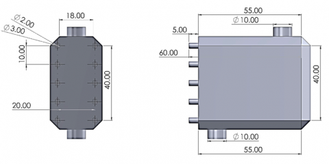
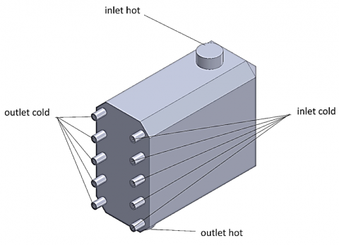
The multi-stage heat exchanger was designed using the Solidworks program as in the dimensions shown in Figure 1.
Figure 1. Design geometry
2.1 Mesh
Tetrahedron mesh tends to work well with curved geometries, so a tetrahedron mesh was used in this research. In ANSYS, users only need to provide input at one stage to create a mesh for a solid geometry or 3D model. In this work, total of (5475654) cells were collected, see Figure 2.
Figure 2. Mesh generated
An exact mesh must be built in order to solve the equations because the simulation method involves complicated algorithms to solve the matrices in the real state. The solution's mesh dependability is then worked on to achieve a steady state with the outcomes. It is important to establish more than one mesh and more than one dependability element because of the various models that have been simulated. As shown in Table 1, the element's value was 5475654 when the outlet hot temperature was 46.68℃.
Table 1. Mesh independency
|
Case |
Element |
Node |
Outlet Hot Temperature (℃) |
|
1 |
2076875 |
624578 |
47.86 |
|
2 |
3865444 |
834543 |
46.77 |
|
3 |
4513467 |
1064576 |
46.69 |
|
4 |
5475654 |
1204993 |
46.68 |
2.2 Governing equations
Modeling boiling phenomena in computational fluid dynamics (CFD) involves solving a set of governing equations that describe the behavior of both the liquid and vapor phases, as well as the heat and mass transfer between them. The specific equations used in a boiling model can vary depending on the level of complexity and the assumptions made. Here, it gives an outline of the key conditions generally utilized in an improved bubbling model:
Continuity equation for liquid phase (incompressible flow):
The continuity equation for the liquid phase represents the conservation of mass and is typically expressed as:
$\nabla \cdot\left(\rho_l \mathbf{u}_l\right)=0$ (1)
where: $\rho_l$ is the density of the liquid phase. $\mathrm{u}_l$ is the speed vector of the fluid stage.
Continuity equation for vapor phase (incompressible flow):
Like the fluid stage, the coherence condition for the fume stage is given by:
$\nabla \cdot\left(\rho_v \mathrm{u}_v\right)=0$ (2)
where: ρv is the thickness of the fume stage. $\mathrm{u}_v$ is the velocity vector of the vapor phase.
Momentum equations:
Navier-Stokes equations are used to describe the momentum of both phases. For the liquid phase:
$\rho_l\left(\frac{\partial \mathrm{u}_l}{\partial t}+\left(\mathrm{u}_l \cdot \nabla\right) \mathrm{u}_l\right)=-\nabla P+\nabla \cdot \tau_l+\rho_l \mathrm{~g}+\mathrm{F}_b$ (3)
And for the vapor phase:
$\rho_v\left(\frac{\partial \mathrm{u}_v}{\partial t}+\left(\mathrm{u}_v \cdot \nabla\right) \mathrm{u}_v\right)=-\nabla P+\nabla \cdot \tau_v+\rho_v \mathrm{~g}$ (4)
where: $P$ is pressure. $\tau_l$ and $\tau_v$ are the viscous stress tensors for the liquid and vapor phases, respectively. g is the acceleration due to gravity. $\mathrm{F}_b$ is the body force term due to boiling effects.
Energy equations:
The energy equations describe the temperature distribution in both phases and account for heat transfer due to boiling and condensation:
For the liquid phase:
$\rho_l c_l\left(\frac{\partial T_l}{\partial t}+\left(\mathrm{u}_l \cdot \nabla\right) T_l\right)=k_l \nabla^2 T_l+Q_b-Q_c$ (5)
And for the vapor phase:
$\rho_v c_v\left(\frac{\partial T_v}{\partial t}+\left(\mathrm{u}_v \cdot \nabla\right) T_v\right)=k_v \nabla^2 T_v+Q_c-Q_b$ (6)
where: $c_l$ and $c_v$ are the specific heat capacities of the liquid and vapor phases, respectively. $k_l$ and $k_v$ are the thermal conductivities of the liquid and vapor phases, respectively.
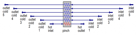
2.3 Boundary conditions
Heat exchangers were dealt with in terms of the diameter of the heat exchange tube for cold water. Sometimes 2 mm was used, sometimes 3 mm, as was the distance between one tube and another. Three dimensions were used: sometimes 5 mm, sometimes 7.5 mm, and sometimes 10 mm, as in Figure 3. Then convert the obtained results to the Hysys program to obtain pinch analysis charts, as shown in Figure 4.
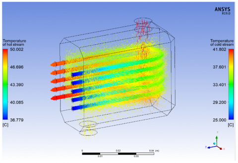
Figure 3. Boundary conditions
Figure 4. HYSYS simulation
In the results section, we will discuss the results obtained through the simulation program regarding heat exchanger temperatures as well as pressure, and then see the results obtained through the HYSYS program, which in turn searches for pinch points.
3.1 Effect of pipe diameter on temperature and pressure drop
The measurement of lines in an intensity exchanger framework fundamentally influences its exhibition, productivity, and viability. Bigger lines give a bigger surface region for warm exchange, improving the rate. Nevertheless, lines that are more modest offer a diminished heat transfer region, requiring longer lines or different passes. Bigger lines have lower liquid speeds, lessening convective intensity, and requiring expanded home time or choppiness. They additionally have lower pressure drops, diminishing energy utilization while possibly compromising intensity and productivity. Bigger lines have longer liquid home times, however, which may increase the risk of fouling or corruption. Additionally, they require more material and framework, while more modest lines are more savvy and simpler to introduce. The determination of the ideal line width in heat exchanger configuration requires cautious consideration of elements like intensity move necessities, liquid properties, framework limitations, and financial matters.
(a)
(b)
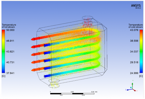
Figure 5. Temperature contour of pipe spacing in the heat exchanger 5 mm and different pipe dimeter (a) 2 mm, (b) 3 mm
It can be seen from Figure 5 that the temperature emerging from the cold water in the first tube reached 40.65 degrees Celsius, while in the second tube it reached 40.79 degrees Celsius. In the third tube, it reached 41.06 degrees Celsius; in the fourth tube, it reached 41.13 degrees Celsius; and in the fifth tube, it reached 41.58 degrees Celsius. Celsius, and at the exit of the hot pipe, it reached 46.82 degrees Celsius. This is in the diameter of 2 mm, but in the diameter of 3 mm, the temperature emerging from the cold water reached 34.04 degrees Celsius in the first pipe, while in the second pipe it was 34.08 degrees Celsius, in the third pipe it reached 34.52 degrees Celsius, and in the fourth pipe. It reached 34.65 degrees Celsius; in the fifth tube, it reached 35.46 degrees Celsius; and at the exit of the hot tube, it reached 45.77 degrees Celsius. This shows the efficiency of the 2 mm diameter in heat exchange compared to the 3 mm diameter.
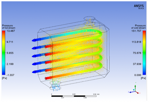
As for Figure 6, which shows the pressure drop in the pipes, it is noted that the amount of pressure in the cold pipes was 151 Pascal, while in the hot pipes the pressure difference reached 13 Pascal. This is in the diameter of 2 mm, but in the diameter of 3 mm, the pressure difference in the cold pipe reached 68 Pascal, but in the hot pipe, it increased to 11 Pascal, and this indicates an improvement in the pressure difference for the 3 mm case compared to the rest of the cases.
(a)
(b)
Figure 6. Pressure contour of pipe spacing in the heat exchanger 5 mm and different pipe dimeter (a) 2 mm, (b) 3 mm
The heat exchangers' performance was assessed with varying pipe diameters (2 mm and 3 mm). Results showed that 2 mm diameter tubes had higher heat exchange efficiency and a more significant pressure drop, which could be beneficial for applications requiring high-pressure differentials. The temperature profile showed that cold-water temperature increased progressively across the tubes, while hot pipe temperature reached 46.82℃.
3.2 Effect of pipe spacing on temperature and pressure drop
The contribution or tube pitch of an intensity exchanger is vital for its presentation, proficiency, and functional qualities. It influences heat movement, liquid elements, and the framework plan. More modest dividing increments heat move regions, however, may prompt a higher strain drop and fouling chances. More extensive dispersing diminishes the heat move region, requiring longer intensity exchanger lengths or extra-intensity move surfaces. More modest dividing brings about more uniform stream dispersion; however, increments may cause vibration and disintegration in the stream. More noteworthy dispersal might prompt non-uniform circulation and problem areas. Lower dispersing increments of pressure drop, however, may require longer stream ways or stream-improvement gadgets. More modest separating expands defenselessness to fouling and support, while more extensive dispersing works with simpler access for cleaning and upkeep exercises. Adjusting compromises between heat move productivity, pressure drop, fouling affinity, framework intricacy, and cost is fundamental for enhancing heat exchanger execution and dependability in different modern applications.
It tends to be seen from Figure 7 that the temperature arising out of the virus water in the principal tube arrived at 40.65 degrees Celsius, while in the second cylinder it arrived at 40.79 degrees Celsius. In the third cylinder, it arrived at 41.06 degrees Celsius; in the fourth cylinder, it arrived at 41.13 degrees Celsius; and in the fifth cylinder, it arrived at 41.58 degrees Celsius. Celsius, and at the exit of the hot line, it arrived at 46.82 degrees Celsius. This is in the pipe dividing 5 mm yet in the line dispersing 7.5 mm; the temperature arising out of the virus water arrived at 42.92 degrees Celsius in the primary line, while in the second line it was 42.88 degrees Celsius, in the third line it arrived at 42.36 degrees Celsius, and in the fourth line. It arrived at 42.12 degrees Celsius; in the fifth cylinder, it arrived at 41.96 degrees Celsius; and at the exit of the hot cylinder, it arrived at 46.51 degrees Celsius. Yet, in the line dispersing 10 mm, the temperature arising out of the virus water arrived at 42.62 degrees Celsius in the main line, while in the second line it was 42.67 degrees Celsius, in the third line it arrived at 42.71 degrees Celsius, and in the fourth line. It arrived at 42.71 degrees Celsius; in the fifth cylinder, it arrived at 42.51 degrees Celsius; and at the exit of the hot cylinder, it arrived at 35.35 degrees Celsius. This shows the productivity of the 7.5 mm pipe separating in heat trade compared with the 5 mm and 10 mm pipe dividing.
(a)
(b)
(c)
Figure 7. Temperature contour of pipe dimeter 2 mm and different pipe spacing in the heat exchanger (a) 5 mm, (b) 7.5 mm, (c) 10 mm
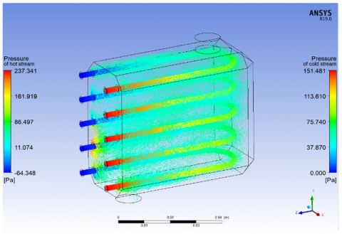
With respect to Figure 8, which shows the tension drop in the lines, it is noticed that the strain in the virus pipes was 151.757 Pascal, while in the hot line the tension contrast arrived at 13.454 Pascal. This is in the line dividing of 5 mm; however, in the line dispersing of 7.5 mm, the strain distinction in the virus pipe arrived at 151.757 Pascal. Yet in the hot line it expanded to 13.467 Pascal, the line separating by 10 mm, the tension contrast in the virus pipe arrived at 151.481 Pascal, yet in the hot line it expanded to 237.341 Pascal, and this demonstrates an improvement in the strain contrast for the 5 mm case compared with the other cases.
(a)
(b)
(c)
Figure 8. Pressure contour of pipe dimeter 2mm and different pipe spacing in the heat exchanger (a) 5 mm, (b) 7.5 mm, (c) 10 mm
The study analyzed the effects of different pipe spacing's (5 mm, 7.5 mm, and 10 mm) on temperature and pressure drop. Results showed that the 7.5 mm spacing provided optimal heat exchange efficiency and a balanced temperature and pressure drop. However, the 10 mm spacing, while providing a lower pressure drop, exhibited lower heat exchange efficiency. The temperature profiles showed that different pipe spacing's led to different temperatures and pressure drops.
3.3 Effect of pipe diameter on pinch point
The pinch point in an intensity exchanger is the temperature distinction between hot and cold streams, where the accessible intensity move potential is boosted. Pipe width influences the squeeze point in more than one way, including heat move region, liquid speed and stream dispersion, pressure drop, and liquid home time. Bigger lines give a more prominent intensity move region, working with more powerful intensity trade between the streams. On the other hand, lines that are more modest offer a decreased heat transfer region, possibly prompting higher temperature contrasts and a more articulated squeeze point. Liquid speed and stream dispersion likewise assume a part, with bigger lines largely having lower pressure drops and more modest lines having higher strain drops. Liquid home time likewise assumes a part, with bigger lines permitting longer home times and more modest lines restricting them. Appropriate thought of line distance across and other plan boundaries is fundamental for improving intensity exchanger execution and effectiveness.
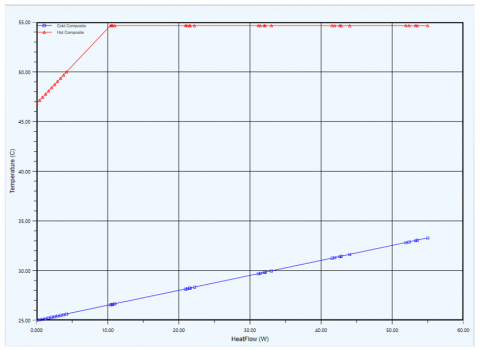
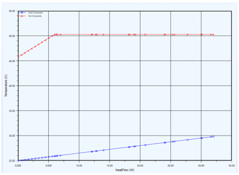
Through the diagram mentioned in Figure 9, when the pipe diameter is 2 mm, it is observed that pinch point hot is 54.65 degrees Celsius, pinch point cold is 41.58 degrees Celsius, pinch point hot is 50.29 degrees Celsius with a diameter of 3 mm, and pinch point cold is 35.46 degrees Celsius. Through these numbers, it is observed that the convergence between the hot composite curve and the cold composite curve is less in the case of 2 mm, and this indicates the advantage of 2 mm in terms of economics for heat exchangers.
(a)
(b)
Figure 9. Composite curve of pipe spacing in the heat exchanger 5 mm and different pipe dimeter (a) 2 mm, (b) 3 mm
The analysis of pinch point temperatures for different pipe diameters showed that 2 mm diameters resulted in lower convergence between hot and cold composite curves, suggesting economic benefits. However, 3 mm diameters had higher pinch point temperature differences, making them less economically favorable. The analysis also showed that pipe spacing affected pinch point temperatures, with 5 mm spacing resulting in lower convergence, 7.5 mm spacing resulting in higher efficiency, and 10 mm spacing being optimal due to lower composite curve convergence.
3.4 Effect of pipe spacing on pinch point
The separating between pipes in an intensity exchanger, otherwise called tube pitch or between tubes dividing, essentially influences the squeeze point and generally execution. More modest separating expands the successful intensity move region, decreasing the squeeze point's greatness. Notwithstanding, bigger separations might require longer intensity exchanger lengths or extra-intensity moving surfaces. More modest separating advances uniform stream dissemination, limiting stream maldistribution, and further developing intensity move consistency. In any case, bigger separation might bring about non-uniform stream dissemination, prompting problem areas or no man's lands. Lower dispersal largely increases pressure drop because of higher liquid speeds and frictional misfortunes between nearby lines. More noteworthy, separating normally brings about a lower pressure drop, but may require longer stream ways or extra stream-improving gadgets. Longer liquid home times may likewise advance a more powerful intensity trade and decrease the squeeze point's extent. Appropriate thought of cylinder pitch, pipe width, stream rates, liquid properties, and intensity exchanger math is pivotal for advancing intensity exchanger execution.
(a)
(b)
(c)
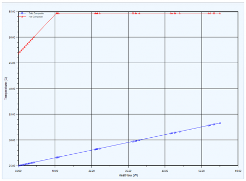
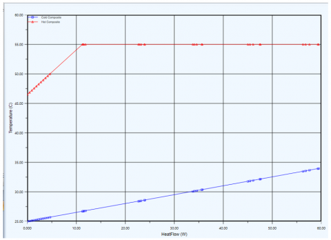
Figure 10. Composite curve of pipe dimeter 2 mm and different pipe spacing in the heat exchanger (a) 5 mm, (b) 7.5 mm, (c) 10 mm
Through the graph referenced in Figure 10, when the line dividing is 5 mm, it is seen that squeeze point hot is 54.65 degrees Celsius, squeeze point cold is 41.58 degrees Celsius, squeeze point hot is 55.60 degrees Celsius with a line dispersing of 7.5 mm, and squeeze point cold is 42.92 degrees Celsius. While squeeze point hot is 53.02 degrees Celsius with a line separation of 10 mm, squeeze point cold is 42.71 degrees Celsius. Through these numbers, it is noticed the combination between hot composite bend and cold composite bend is less because of 10 mm, and this demonstrates the benefit of 10 mm concerning financial matters for heat exchangers.
The results of this study highlight the complex interplay between tube diameter and pipe spacing in optimizing the performance of multi-stage micro heat exchangers. Smaller tube diameters (2 mm) offer higher heat transfer efficiency and better economic performance but come with higher-pressure drops. Optimal pipe spacing (7.5 mm) provides the best balance between heat transfer efficiency and pressure drop, leading to improved pinch point performance and economic benefits.
These findings underscore the importance of carefully considering both geometric and operational parameters in the design and optimization of micro heat exchangers to achieve the desired performance outcomes. By combining advanced computational fluid dynamics (CFD) simulations with pinch analysis, this study provides comprehensive guidelines for enhancing the efficiency and sustainability of multi-stage MHEs in various industrial applications.
The study reveals that the optimal tube diameter for multi-stage micro heat exchangers (MHEs) is 2 mm, which offers higher heat exchange efficiency due to the increased surface area to volume ratio. This results in better thermal contact and improved convective heat transfer. However, smaller diameters are preferred for applications requiring maximum heat transfer efficiency. The optimal pipe spacing is 7.5 mm, which balances heat transfer efficiency and pressure drop, achieving the highest heat exchange efficiency and optimal pinch point performance. The 7.5 mm spacing is the most practical and efficient choice for optimizing MHE performance. The pinch point analysis shows that these configurations show lower convergence between hot and cold composite curves, indicating effective use of available temperature differences and economic benefits.
The results will be summarized as follows:
1. The temperature of the cold water in the first tube reached 40.65 degrees Celsius, while the temperature in the 3 mm diameter reached 34.04 degrees Celsius. The efficiency of the 2 mm diameter in heat exchange was higher than that of the 3 mm diameter. The pressure drop in the pipes was 151 Pascal in the cold and 13 Pascal in the hot, with a pressure difference of 68 Pascal in the cold and 11 Pascal in the hot. This indicates an improvement in pressure difference for the 3 mm diameter.
2. The temperature of virus water in a pipe dividing 5 mm by 7.5 mm was measured, with the primary tube reaching 40.65 degrees Celsius, the second cylinder at 40.79, the third cylinder at 41.06, the fourth cylinder at 41.13, and the fifth cylinder at 41.58 degrees Celsius. The output temperature was 46.82 degrees Celsius in the hot line. The 7.5 mm pipe separating showed higher heat trade productivity compared to the 5 mm and 10 mm pipe dividing. The strain contrast in the lines was 151.757 Pascal in the 5mm pipe dividing line, while it expanded to 13.467 Pascal in the hot line. The strain contrast improved for the 5 mm pipe separating line.
3. The pipe diameter of 2 mm shows a lower convergence between hot and cold composite curves, indicating economic benefits for 2 mm heat exchangers. The line dividing 5 mm shows a lower combination between hot and cold composite bends, indicating financial benefits for 10 mm heat exchangers. The pinch point hot and cold temperatures are 54.65, 41.58, and 35.46 degrees Celsius, respectively.
[1] Vaisi, A., Javaherdeh, K., Moosavi, R. (2022). Experimental investigation of the thermal performance in a single-component two-phase flow in multistream multi-fluid plate-fin heat exchangers. International Journal of Thermal Sciences, 171: 107194. https://doi.org/10.1016/j.ijthermalsci.2021.107194
[2] Hosseinnia, S.M., Sorin, M. (2021). A systematic pinch approach to integrate stratified thermal energy storage in buildings. Energy and Buildings, 232: 110663. https://doi.org/10.1016/j.enbuild.2020.110663
[3] Abu-Hamdeh, N.H., Alsulami, R.A., Rawa, M.J.H., Aljinaidi, A.A., Alazwari, M.A., Eltaher, M.A., Almitani, K.H., Alnefaie, K.A., Abusorrah, A.M., Sindi, H.F., Goodarzi, M., Safaei, M.R. (2021). A detailed hydrothermal investigation of a helical micro double-tube heat exchanger for a wide range of helix pitch length. Case Studies in Thermal Engineering, 28: 101413. https://doi.org/10.1016/j.csite.2021.101413
[4] Ghorbani, B., Ebrahimi, A., Skandarzadeh, F., Ziabasharhagh, M. (2021). Energy, exergy and pinch analyses of an integrated cryogenic natural gas process based on coupling of absorption–compression refrigeration system, organic Rankine cycle and solar parabolic trough collectors. Journal of Thermal Analysis and Calorimetry, 145: 925-953. https://doi.org/10.1007/s10973-020-10158-3
[5] Yong, W.N., Liew, P.Y., Woon, K.S., Wan Alwi, S.R., Klemeš, J.J. (2021). A pinch-based multi-energy targeting framework for combined chilling heating power microgrid of urban-industrial symbiosis. Renewable and Sustainable Energy Reviews, 150: 111482. https://doi.org/10.1016/j.rser.2021.111482
[6] Niroomand, R., Saidi, M.H., Hannani, S.K. (2020). A general multi-scale modeling framework for two-phase simulation of multi-stream plate-fin heat exchangers. International Journal of Heat and Mass Transfer, 156: 119730. https://doi.org/10.1016/j.ijheatmasstransfer.2020.119730
[7] Klemeš, J.J., Wang, Q.W., Varbanov, P.S., Zeng, M., Chin, H.H., Lal, N.S., Li, N.Q., Wang, B., Wang, X.C., Walmsley, T.G. (2020). Heat transfer enhancement, intensification and optimisation in heat exchanger network retrofit and operation. Renewable and Sustainable Energy Reviews, 120: 109644. https://doi.org/10.1016/j.rser.2019.109644
[8] Mirzaee, M., Zare, R., Sadeghzadeh, M., Maddah, H., Ahmadi, M.H., Acıkkalp, E., Chen, L. (2019). Thermodynamic analyses of different scenarios in a CCHP system with micro turbine – Absorption chiller, and heat exchanger. Energy Conversion and Management, 198: 111919. https://doi.org/10.1016/j.enconman.2019.111919
[9] Jankowski, M., Borsukiewicz, A., Szopik-Depczyńska, K., Ioppolo, G. (2019). Determination of an optimal pinch point temperature difference interval in ORC power plant using multi-objective approach. Journal of Cleaner Production, 217: 798-807. https://doi.org/10.1016/j.jclepro.2019.01.250
[10] Chen, S.Q., Xu, J., Dong, X.Z., Zhang, H.L., Gao, Q., Tan, C.Q. (2018). Pinch point analysis of heat exchange for liquid nature gas (LNG) cryogenic energy using in air separation unit. International Journal of Refrigeration, 90: 264-276. https://doi.org/10.1016/j.ijrefrig.2017.12.015
[11] Han, T., Wang, C.A., Zhu, C.Z., Che, D.F. (2018). Optimization of waste heat recovery power generation system for cement plant by combining pinch and exergy analysis methods. Applied Thermal Engineering, 140: 334-340. https://doi.org/10.1016/j.applthermaleng.2018.05.039
[12] Kim, Y., Kim, M., Ahn, C., Kim, H.U., Kang, S.W., Kim, T. (2017). Numerical study on heat transfer and pressure drop in laminar-flow multistage mini-channel heat sink. International Journal of Heat and Mass Transfer, 108: 1197-1206. https://doi.org/10.1016/j.ijheatmasstransfer.2016.12.025
[13] Boyaghchi, F.A., Chavoshi, M. (2017). Multi-criteria optimization of a micro solar-geothermal CCHP system applying water/CuO nanofluid based on exergy, exergoeconomic and exergoenvironmental concepts. Applied Thermal Engineering, 112: 660-675. https://doi.org/10.1016/j.applthermaleng.2016.10.139
[14] Omidvarnia, F., Hansen, H.N., Sarhadi, A. (2016). A systematic approach applied in design of a micro heat exchanger. The International Journal of Advanced Manufacturing Technology, 82: 1187-1195. https://doi.org/10.1007/s00170-015-7401-y
[15] Feng, H.C., Zhong, W., Wu, Y.L., Tong, S.G. (2014). Thermodynamic performance analysis and algorithm model of multi-pressure heat recovery steam generators (HRSG) based on heat exchangers layout. Energy Conversion and Management, 81: 282-289. https://doi.org/10.1016/j.enconman.2014.02.060
[16] Ruohonen, P., Hippinen, I., Tuomaala, M., Ahtila, P. (2010). Analysis of alternative secondary heat uses to improve energy efficiency-case: A Finnish mechanical pulp and paper mill. Resources, Conservation and Recycling, 54(5): 326-335. https://doi.org/10.1016/j.resconrec.2009.07.002
[17] Fan, Y.L., Luo, L.G. (2008). Recent applications of advances in microchannel heat exchangers and multi-scale design optimization. Heat Transfer Engineering, 29(5): 461-474. https://doi.org/10.1080/01457630701850968
[18] Okabe, T., Foli, K., Olhofer, M., Jin, Y., Sendhoff, B. (2003). Comparative studies on micro heat exchanger optimization. In The 2003 Congress on Evolutionary Computation, 2003. CEC '03, Canberra, ACT, Australia, pp. 647-654. https://doi.org/10.1109/CEC.2003.1299637
[19] Reda, S., Majdi, H. (2023). Evaluation of double pipe heat exchanger performance with right angle turbulator. Al-Rafidain Journal of Engineering Sciences, 1(1): 58-65. https://doi.org/10.61268/91tf8086
[20] Majel, B., Kamal Hasan, W. (2023). Heat transfer augmentation in fin and tube heat exchanger embedded with vortex generators. Al-Rafidain Journal of Engineering Sciences, 1(1): 42-50. https://doi.org/10.61268/qk2k0g77