Ouyoussef Nouhaila*![]() | Moustabchir Hassane
| Moustabchir Hassane![]()
© 2024 The authors. This article is published by IIETA and is licensed under the CC BY 4.0 license (http://creativecommons.org/licenses/by/4.0/).
OPEN ACCESS
The exhaust manifold system plays a vital role in the internal combustion engine of a vehicle, functioning in conditions of high temperature and pressure. The objective of this analysis is to assess how the presence of the crack influences the pressure drop across the exhaust manifold. Understanding pressure drop is essential in determining the efficiency of the exhaust system and its effect on engine performance. Furthermore, we investigate how a crack in the exhaust manifold affects the flow patterns of exhaust gases, including changes in velocity, pressure distribution, and turbulence within the manifold; The results of the analysis show that the crack has various implications for both the performance and structural integrity of the manifold. It causes an increase in pressure drop across the manifold, resulting in reduced engine efficiency. Additionally, the crack induces turbulence or vortex formation in the exhaust gases, further impacting the system’s performance, and finally, the impact of the presence of a crack typically results in an elevated coefficient of friction.
crack, exhaust manifold, pressure, skin friction coefficient, temperature, turbulence kinetic energy, velocity
In the highly competitive automotive industry, there is a pressing need for durable, cost-effective, and lightweight automotive products. To meet these demands, powerful numerical techniques are increasingly being utilized to solve structural problems. One focal point involves advancing exhaust systems to diminish noise and emissions, bolster durability, mitigate corrosion, enhance serviceability, and maintain economic feasibility. Given the critical role of the exhaust system in removing hazardous fumes, extensive research and analysis are being conducted to investigate and analyze crack propagation [1-4]. The objective of this paper is to assess the fracture and crack propagation analysis of the exhaust manifold when subjected to thermo-mechanical loads. Fracture toughness analysis is necessary to determine the initiation and propagation of cracks under applied stress. Crack propagation occurs when the material's fracture toughness exceeds the critical fracture toughness. Fayed [5] illustrated crack growth in naval gas turbine exhaust Systems, especially those located at the weld toes of butt and fillet weld joints near the lower support ring, have been analyzed by the authors. They computed Von Mises stress and nominal principal stresses in the area and anticipated an increase in design and fatigue life up to 6.e4 cycles. This is a crucial area and any improvements made here would be significant. In a study by Gorji et al. [6], the exhaust system of an ultra-fuel-efficient vehicle was analyzed using CFD to investigate turbulent flow in the exhaust manifold and achieve a smoother flow. Consequently, they successfully optimized the exhaust manifold design in terms of both materials and geometry. On the other side Hidayanti et al. [7] introduced a method to determine the fatigue life of mounting brackets using CEA, as opposed to physical testing. They analyzed the exhaust system using MSC/NASTRAN to identify the primary cause of high stress in critical areas and the predominant mode leading to failures; Lee et al. [8] conducted a thermomechanical analysis on a tractor exhaust manifold, utilizing Austenitic Stainless Steel-321 as the material. The objective was to examine the response of the manifold at elevated temperatures, with thermal effects factored in to assess the outcomes of the FEA simulation. Using a free vibration-based modal analysis, they determined the fundamental frequencies, Manohar and Krishnaraj [9] focus on redesigning exhaust manifolds to evaluate thermal stresses and deflections under diverse conditions. It aims to address defects such as cracks and ensure design reliability. The study suggests profile redesigns to mitigate turbulence effects. Utilizing advanced software tools, the research conducts fluid dynamics analysis to assess flow characteristics and static structural analysis to evaluate strength under thermal loads, aiding in material selection for optimal performance. In a study by Shinde and Panchwadkar [10], this article investigates thermal fatigue in exhaust manifolds under varying conditions, assessing grey cast iron, stainless steel, and D5S alloy. Results show grey cast iron experiences the highest stresses, stainless steel exhibits notable deformation, and D5S alloy has a shorter lifespan. Insights from this study inform exhaust manifold design and material selection for improved performance. The main objective of this study is to analyze the impact of cracks in the exhaust manifold on specific characteristics, such as the pressure distribution, as well as the changes in velocity and turbulence within the manifold. The article is organized into multiple segments, commencing with a flow chart illustrating the analysis method in the initial section, followed by an exploration of the simulation and development process in the subsequent part. Section 3 delves into mathematical modeling, while Section 4 outlines the CFD analysis of the exhaust manifold in the presence of the crack. The primary outcomes of the simulations are detailed in Section 5. Ultimately, the article concludes by summarizing the study's findings and results.
Conducting a computational fluid dynamics (CFD) analysis of a cracked exhaust manifold involves simulating the flow of exhaust gases within the manifold [11], taking into account the presence of the crack. This type of analysis is important for understanding the impact of the crack on fluid flow patterns, pressure distribution, and the overall performance of the exhaust system.
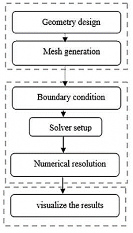
Figure 1. Analysis method
The process of analyzing a structure involves several essential steps, which are depicted in the flowchart presented in Figure 1. First, a detailed 3D model of the exhaust manifold must be developed using CAD software (CATIA V5 R21). This should include an accurate representation of any predefined internal crack on the exhaust manifold, as well as the definition of material properties such as thermal conductivity, and density. These properties are crucial for accurate heat transfer simulations, and the model of turbulence adopted should also be defined at this stage. Next, a high-quality mesh should be generated for the computational domain. The mesh needs to possess sufficient refinement to capture the complexities inherent in the geometry, particularly near critical areas such as bends and junctions. Once the mesh is generated, boundary conditions for the simulation should be defined. This includes specifying inlet conditions for the exhaust gases, such as temperature, pressure, and flow rates. An appropriate CFD solver should then be chosen based on the nature of the simulation. After setting up the simulation, it should be executed, and convergence should be monitored to ensure that the solution reaches a stable state. Settings may need to be adjusted to improve convergence. Finally, the simulation results should be analyzed, visualizing and interpreting velocity contours, pressure distributions, temperature profiles, and any other relevant parameters. These results should be compared with those obtained from an exhaust manifold without a crack, and the interpretation of the results should be done accordingly.
The selection of the k-omega SST model for simulating flow1 was based on the recognition that the k-epsilon model lacks accuracy in capturing the turbulent characteristics of boundary layer 3 until detachment occurs. The SST turbulence model is a hybrid two-equation model that seamlessly transitions from the k-omega standard model employed in the boundary layer to the k model as the flow moves away from the surface, thereby restricting its influence. This model incorporates an adjusted formulation of turbulent viscosity that considers the impact of transporting primary shear stresses.
Table 1 compares different models used for calculating flow, as described in reference [12]. The models include K-Epsilon, K-Omega, and K-Omega SST.
Table 1. Comparison of flow calculation models [4]
|
K-Epsilon |
K-Omega |
K-Omega SST |
|
k-kinetic energy of turbulence |
||
|
The scale of turbulence |
$\omega-\mathrm{k} \epsilon$ (vorticity) |
Combination of models $\mathrm{k}-\epsilon$ and $\mathrm{k}-\omega$ |
|
The flow is fully turbulent |
Laminar-turbulent flow |
Laminar-turbulent flow |
The SST k-omega turbulence model serves as a computational fluid dynamic turbulence model, offering refinements to the standard model through the following features:
It is a two-equation model that solves two turbulence-related variables, k (turbulent kinetic energy) and omega (specific dissipation rate) [13-23].
Turbulence Kinetic Energy (k):
$\frac{\partial(\rho \mathrm{k})}{\partial \mathrm{t}}+\frac{\partial\left(\rho \mathrm{k} U_i\right)}{\partial \mathrm{x}_i}=\frac{\partial}{\partial x}\left[\tau_k \frac{\partial(\rho \mathrm{k})}{\partial \mathrm{x}_j}\right]+G_k-Y_k+S_k$ (1)
Specific Dissipation Rate (ω):
$\frac{\partial(\rho \omega)}{\partial \mathrm{t}}+\frac{\partial\left(\rho \omega U_i\right)}{\partial \mathrm{x}_i}=\frac{\partial}{\partial x}\left[\tau_\omega \frac{\partial(\rho \omega)}{\partial \mathrm{x}_j}\right]+G_\omega-Y_\omega+S_\omega$ (2)
where:
The SST k-omega model solves two transport equations for k and omega, in addition to the continuity, momentum, and energy equations. The transport equation for k accounts for the production, diffusion, and dissipation of turbulent kinetic energy, while the transport equation for omega accounts for the production and destruction of a specific dissipation rate.
Skin friction coefficient Cf [24-26]:
$C_f=\frac{2 \tau}{\rho U_b^2}$ (3)
where:
The SST k-omega model combines the advantages of the k-omega and k-epsilon models to improve accuracy in a wide range of flow conditions. The SST k-omega model is widely used in CFD simulations of turbulent flows in various engineering applications, such as aerodynamics, combustion, and heat transfer.
4.1 Modeling and meshing
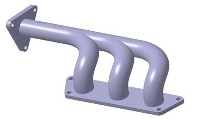
The modeling of the system is carried out using CATIA V5 R21 software using the part design. The CAD model of the manifold exhaust system is shown as above Figure 2.
Figure 2. Perspective view of the exhaust manifold
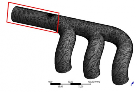
To examine the exhaust manifold we utilized the FEM to derive an approximate solution based on partial differential equations. It is impractical to solve these equations for the entire region simultaneously, especially for complex physical problems. Therefore, to obtain a numerical solution describing fluid flow, the domain should be divided into elements, in which the equations are solved for every cell, the exhaust manifold was meshed to 81851 Nodes using a tetrahedral mesh. To gain more detailed insights into the impact of the crack on specific characteristics of the exhaust manifold, we will be focusing on the pipe of the exhaust manifold that has been subjected to a semi-elliptical fracture [27], which is denoted by its red frame as shown in Figure 3.
Figure 3. Meshed exhaust manifold with a crack
An inflation mode was used also with 3 layers, adding additional layers of mesh cells near the solid boundaries where the flow gradients are significant. These layers are progressively refined towards the wall, allowing for better resolution of the boundary layer and capturing the flow phenomena occurring in that region, this technique is used in computational fluid dynamics (CFD) simulations to capture the near-wall flow behavior with higher resolution.
4.2 Material fluid properties
The exhaust gas will be treated as an incompressible fluid functioning within the temperature range of 800K to 810K. The materials chosen in Ansys V19 are Nitrogen NOx, Gasoline, and Air [28, 29]. The material properties for these conditions are listed in Table 2.
Table 2. Material properties
|
|
Nitrogen NOx |
Air+Gasoline (c8h18) |
|
Density (kg/m3) |
1 |
1.0685 |
|
Viscosity (Pa-s) |
1.72 e-5 |
3.0927 e-5 |
|
Specific heat (J/kg-K) |
-- |
0 |
|
Thermal conductivity (W/m-K) |
0.0454 |
0.0250 |
Table 3. Boundary conditions
|
Parameters |
Value |
|
Temperature (K) |
800 |
|
Young’s Modulus (GPa) |
2.e5 |
|
Density (Kg/m2) |
7.85e-6 |
|
Wall Shear (Mpa) |
76923 |
|
Relative Wall Thickness(mm) |
0.1 |
|
Poisson’s Ratio |
0.25 |
4.3 Boundary condition
It is crucial to accurately specify the boundary conditions of the exhaust manifold. The fluid's inlet characteristics, such as velocity and pressure, must be indicated [30-32]. Fluid and solid domains are delimited using wall boundary conditions as described in Table 3.
Using the Ansys tool, the thermal model has been elaborated to examine the temperature, pressure distribution, and heat transfer inside the exhaust manifold and describe fluid flow in it.
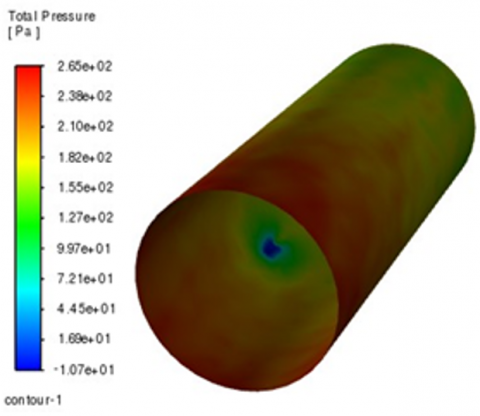
5.1 Pressure
The Figure 4 shows how the pressure is distributed inside the exhaust manifold, From the pressure contours it can be observed that the pressure from inlet pipe one to the exit is decreasing, which is also a required condition for the flow to happen in the outlet direction, the minimum back pressure is observed in the crack region ≈1.07 Pa, Yet the maximum back pressure noticed is 266 Pa.
Figure 4. Pressure distribution
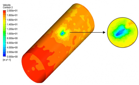
5.2 Velocity
As per the boundary conditions, the inlet is set to 20m/s, we can notice in the Figure 5 that the velocity is decreasing through the outlet of the pipe. It’s remarkable also that there is a discernible reduction in fluid velocity at the center of the crack. This implies that the crack acts as a flow restriction or an obstruction to the fluid passing through it.
Figure 5. Velocity distribution
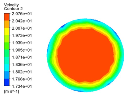
Figure 6. Velocity contour of the exhaust manifold outlet
In the Figure 6, Moving from the central part of the pipe toward the wall, there is a gradual decrease in fluid velocity. This is characteristic of a parabolic velocity profile, with maximum velocity at the center at 20.76 m/s and a decrease toward the walls at 17.3 m/s.
5.3 Turbulence kinetic energy
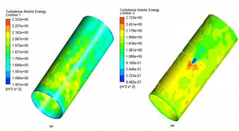
The Figure 7 depicts the spatial distribution of TKE along the cracked pipe (b) and the standard pipe (a), we can observe that the presence of the crack leads to an increase in TKE [max=2.7m2.s2]. The irregularities introduced by the crack disrupt the smooth flow, generating turbulence, we notice also that in the vicinity of the crack, there is a wide range in TKE value [Max=2.7m2.s2–Min=8.482e−7m2.s2] contrary to the standard pipe [Max=2.352m2.s2–Min=1.401m2.s2] that confirms where turbulence is particularly intense.
Figure 7. Turbulence kinetic energy for cracked vs standard exhaust manifold
5.4 Skin friction coefficient, Cf
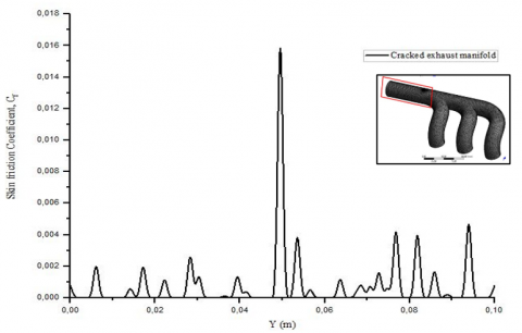
Figure 8 presented below shows how the skin friction coefficient varies along the wall of the exhaust manifold, with a special focus on the impact of a visible crack.
At the start position, which is closest to position 0, the skin friction coefficient is relatively low due to smoother surface conditions. As we move towards the midsection positions along the surface, there is a noticeable increase in the skin friction coefficient until we see a peak at the wall position of 0.05 m [0.018]. This peak is caused by the presence of the crack, which introduces topographical irregularities, altered material properties, and perturbations leading to a substantial amplification of frictional resistance. As we approach the end of the pipe, we can see a gradual decrease in the skin friction coefficient. Despite this decline, the coefficient remains at a high level, emphasizing the long-lasting impact of the initial crack.
Figure 8. Skin friction coefficient on the wall of the exhaust manifold
In conclusion, this study focused on the structural design and computational fluid dynamics (CFD) analysis of a cracked exhaust. The analysis method involved a comprehensive approach, including the development of a 3D model using CAD software, mesh generation, defining material properties, and conducting CFD simulations. The SST k-omega turbulence model is widely used for simulating turbulent flows in various engineering applications. The results of the CFD analysis revealed significant implications of the crack on the exhaust manifold’s performance and structural integrity. The crack led to a decrease in pressure drop across the manifold. Moreover, the presence of the crack induced turbulence and vortex formation in the exhaust gases, further impacting the system’s performance. The velocity contours indicated a reduction in fluid velocity at the center of the crack, suggesting that the crack acted as a flow restriction or obstruction. Additionally, the analysis of Turbulence Kinetic Energy (TKE) highlighted increased turbulence in the cracked manifold compared to the standard one. the comprehensive understanding of the skin friction coefficient variations along the wall of the exhaust manifold provides valuable insights for structural assessment and emphasizes the critical importance of addressing and mitigating the consequences of the identified crack in the exhaust manifold.
In practical terms, these findings underline the importance of addressing cracks in exhaust manifolds promptly, as they can compromise engine efficiency and contribute to increased turbulence in exhaust gases. Turbulence can also contribute to increased noise and vibration levels within the exhaust system. This not only affects the comfort of vehicle occupants but may also indicate structural issues that could lead to further damage.
As a potential future direction, we could investigate the implementation of generative design techniques to automatically create novel exhaust manifold designs. By establishing specific design constraints and performance goals and utilizing generative design algorithms, we can generate an optimized geometry for the exhaust manifold that maximizes efficiency, minimizes weight, and can endure thermal stresses.
[1] Adanta, D., Fattah, I.R., Muhammad, N.M. (2020). Comparison of standard k-epsilon and SST k-omega turbulence model for breastshot waterwheel simulation. Journal of Mechanical Science and Engineering, 7(2): 39-44. https://doi.org/10.36706/jmse.v7i2.44
[2] Akhi, A.H., Dhar, A.S. (2021). Stress intensity factors for external corrosions and cracking of buried cast iron pipes. Engineering Fracture Mechanics, 250: 107778. https://doi.org/10.1016/j.engfracmech.2021.107778
[3] Blocken, B., van Druenen, T., Toparlar, Y., Malizia, F., Mannion, P., Andrianne, T., Marchal, T., Maas, G.J., Diepens, J. (2018). Aerodynamic drag in cycling pelotons: New insights by CFD simulation and wind tunnel testing. Journal of Wind Engineering and Industrial Aerodynamics, 179: 319-337. https://doi.org/10.1016/j.jweia.2018.06.011
[4] Cen, Z.L. (2014). A comparative study of omega RSM and RNG k–ε model for the numerical simulation of a hydrocyclone. Iranian Joumal of Chemistry and Chemical Engineering, 33(3): 53-61. https://doi.org/10.30492/IJCCE.2014.11331
[5] Fayed, A. (2017). Numerical analysis of mixed mode I/II stress intensity factors of edge slant cracked plates. Engineering Solid Mechanics, 5(1): 61-70. http://doi.org/10.5267/j.esm.2016.8.001
[6] Gorji, S., Seddighi, M., Ariyaratne, C., Vardy, A.E., O’Donoghue, T., Pokrajac, D., He, S. (2014). A comparative study of turbulence models in a transient channel flow. Computers & Fluids, 89: 111-123. https://doi.org/10.1016/j.compfluid.2013.10.037
[7] Hidayanti, F., Adi, K.A., Wati, E.K. (2020). Developing racing exhaust system performance using computational fluid dynamics software. AIP Conference Proceedings, 2262(1): 030016. https://doi.org/10.1063/5.0016170
[8] Lee, G.B., Park, S.H., Jang, Y.Y., Huh, N.S., Park, S.H., Park, N.H., Park, J. (2022). Development of automatic crack growth simulation program based on finite element analysis. Applied Sciences, 12(6): 3075. https://doi.org/10.3390/app12063075
[9] Manohar, D.S., Krishnaraj, J. (2018). Modeling and analysis of exhaust manifold using CFD. IOP Conference Series: Materials Science and Engineering, 455(1): 012132. https://doi.org/10.1088/1757-899X/455/1/012132
[10] Shinde, N.N., Panchwadkar, A.A. (2020). Thermal fatigue analysis of exhaust manifold. International Journal for Research in Applied Science & Engineering Technology, 8(11): 370-378.
[11] Mahfoze, O., Laizet, S. (2017). Skin-friction drag reduction in a channel flow with streamwise-aligned plasma actuators. International Journal of Heat and Fluid Flow, 66: 83-94. https://doi.org/10.1016/j.ijheatfluidflow.2017.05.013
[12] Andrych-Zalewska, M., Wielki, Ł., Ziora, K. (2019). CFD analysis of the Ferrari 348 GTC intake system. AUTOBUSY-Technika, Eksploatacja, Systemy Transportowe, 24(6): 128-133. https://doi.org/10.24136/atest.2019.138
[13] Liu, H.J., Zhi, S.Y. (2012). Exhaust system finite element analysis and optimizing design. Advanced Materials Research, 538: 590-594. https://doi.org/10.4028/www.scientific.net/AMR.538-541.590
[14] Martins, R.F., Viegas, J.C., Cruz, H.J. (2011). Fatigue life assessment of an exhaust system for naval gas turbines. Procedia Engineering, 10: 2548-2553. https://doi.org/10.1016/j.proeng.2011.04.420
[15] Ram, G.V., Sharan, G.N., Kumar, T.P., Tanish, P. (2021). Design and analysis of exhaust system for ultra-fuelefficient vehicles. IOP Conference Series: Materials Science and Engineering, 1033(1): 012019. https://doi.org/10.1088/1757-899X/1033/1/012019
[16] Sasikumar, P., Sujatha, C., Chinnaraj, K. (2017). Transient fatigue analysis of exhaust system mounting brackets for commercial vehicle-correlation. SAE Technical Paper. https://doi.org/10.4271/2017-01-1333
[17] Tomboulides, A., Aithal, S.M., Fischer, P.F., Merzari, E., Obabko, A.V., Shaver, D.R. (2018). A novel numerical treatment of the near-wall regions in the k-ω class of RANS models. International Journal of Heat and Fluid Flow, 72: 186-199. https://doi.org/10.1016/j.ijheatfluidflow.2018.05.017
[18] Bentoto, W., Zaydan, M., Alaoui, H.A., Essaghir, E., Sehaqui, R. (2023). Mixed convection of a MHD oscillatory laminar flow of a nanofluid (Gold-Kerosene oil) in a vertical channel. Statistics, Optimization & Information Computing, 11(1): 55-69. https://doi.org/10.19139/soic-2310-5070-1725
[19] Kumar, A., Bharti, R.P. (2023). Evaluation of RANS-based turbulence models for isothermal flow in a realistic can-type gas turbine combustor application. arXiv preprint arXiv:2312.14459. https://doi.org/10.48550/arXiv.2312.14459
[20] Liu, X., Deng, B., Han, X., Peng, S. (2023). Numerical simulation of temperature and carbon dioxide distribution in indoor environment using two-equation turbulence models. Iranian Journal of Science and Technology, Transactions of Civil Engineering, 47(3): 1893-1907. https://doi.org/10.1007/s40996-022-01007-4
[21] Kim, D., Park, J., Park, J.S., Lee, S. (2023). Optimized Ristorcelli’s compressibility correction to the k-ω SST turbulence model for base flow analysis. International Journal of Aeronautical and Space Sciences, 24: 1147-1159. https://doi.org/10.1007/s42405-023-00599-z
[22] Apte, D., Ge, M., Coutier-Delgosha, O. (2023). A comparative evaluation of turbulence models for simulation of unsteady cavitating flows. arXiv preprint arXiv:2303.08285. https://doi.org/10.48550/arXiv.2303.08285
[23] Könözsy, L. (2020). A New Hypothesis on the Anisotropic Reynolds Stress Tensor for Turbulent Flows: Volume II: Practical Implementation and Applications of an Anisotropic Hybrid k-Omega Shear-Stress Transport/Stochastic Turbulence Model (Vol. 125). Springer Nature.
[24] Mahfoze, O., Laizet, S. (2017). Skin-friction drag reduction in a channel flow with streamwise-aligned plasma actuators. International Journal of Heat and Fluid Flow, 66: 83-94. https://doi.org/10.1016/j.ijheatfluidflow.2017.05.013
[25] Housiadas, K.D., Beris, A.N. (2013). On the skin friction coefficient in viscoelastic wall-bounded flows. International Journal of Heat and Fluid Flow, 42: 49-67. https://doi.org/10.1016/j.ijheatfluidflow.2012.11.004
[26] Ricco, P., Skote, M., Leschziner, M.A. (2021). A review of turbulent skin-friction drag reduction by near-wall transverse forcing. Progress in Aerospace Sciences, 123: 100713. https://doi.org/10.1016/j.paerosci.2021.100713
[27] Montassir, S., Moustabchir, H., Elkhalfi, A. (2023). Application of NURBS in the fracture mechanics framework to study the stress intensity factor. Statistics, Optimization & Information Computing, 11(1): 106-115. https://doi.org/10.19139/soic-2310-5070-1553
[28] Bajpai, K., Chandrakar, A., Agrawal, A., Shekhar, S. (2017). CFD analysis of exhaust manifold of SI engine and comparison of back pressure using alternative fuels. IOSR Journal of Mechanical and Civil Engineering, 14(1): 23-29. https://doi.org/10.9790/1684-1401012329
[29] Umesh, K.S., Rajagopal, V.P.K. (2013). CFD analysis of exhaust manifold of multi-cylinder SI engine to determines to determine optimal geometry for reducing emissions. International Journal of Automobile Engineering Research and Development, 45-56.
[30] Allawi, M.K., Oudah, M.H., Mejbel, M.K. (2019). Analysis of exhaust manifold of spark-ignition engine by using computational fluid dynamics (CFD). Journal of Mechanical Engineering Research and Developments, 42(5): 211-215. http://doi.org/10.26480/jmerd.05.2019.211.215
[31] Babali, B.A., Seetharamu, K.N. (2017). CFD analysis of exhaust manifold of a multi-cylinder engine. International Journal of Electronics, Electrical and Computational System, 1-10.
[32] Sahoo, D.K., Thiya, R. (2019). Coupled CFD–FE analysis for the exhaust manifold to reduce stress of a direct injection-diesel engine. International Journal of Ambient Energy, 40(4): 361-366. https://doi.org/10.1080/01430750.2017.1399457