Riyam Ali Khaled*![]() | Khudheyer S. Mushatet
| Khudheyer S. Mushatet![]()
© 2023 IIETA. This article is published by IIETA and is licensed under the CC BY 4.0 license (http://creativecommons.org/licenses/by/4.0/).
OPEN ACCESS
A numerical investigation into the thermal-hydraulic performance of double elliptical twisted tubes fitted with twisted tape has been conducted. The fluid flow and heat transfer in the twisted double elliptical tubes heat exchanger were modeled utilizing Navier-Stokes, energy, and turbulence equations. The governing equations were resolved using ANSYS Fluent 23.1. Twisting ratios of 5 for twisted tubes and 4 for twisted tape were applied. The Reynolds number was varied within the range of 5000 to 25000. A counter-flow arrangement was established by inputting hot water into the inner tube and cold water into the outer tube. The introduction of twisted tape (TT) resulted in enhanced fluid and centrifugal force mixing near the wall, thereby significantly influencing heat transfer in this region. The study revealed that the heat transfer and performance were notably improved in comparison to a plain double-tube heat exchanger. Furthermore, the heat exchanger's effectiveness was found to increase by 75% at a Reynolds number of 5000.
double elliptical twisted tubes, twisted tape, heat exchanger, CFD
Heat exchangers are integral to various commercial and engineering endeavors, rendering their design a complex and challenging field. Independent of fiscal considerations and long-term performance concerns, a comprehensive hydraulic and thermal performance analysis is mandatory in heat exchanger design [1]. While optimization techniques can foster improvements in thermal performance and efficiency, they often yield a higher pressure drop and additional pump workload. Heat transfer enhancement methodologies can be bifurcated into "active" and "passive" types. The passive approach has garnered substantial interest among researchers and engineers due to its cost-effectiveness and ease of implementation. Passive systems often employ flow devices such as twisted tape, which induces secondary flows atop the axial flow, thereby augmenting turbulence. Consequently, enhanced mixing can thin the boundary layer within the heat exchanger tube [2].
In their work, Mushatet et al. [3] scrutinized several configurations of tapered twisted tape housed within a heated tube both experimentally and numerically for augmented thermal and hydrodynamic performance. Investigations were conducted within turbulent Reynolds numbers ranging from 10,000 to 400,000, with the peak thermal efficiency gain recorded at 137%. Conversely, Luo et al. [4] numerically analyzed the fluid flow and heat transfer characteristics for co-twisting oval pipes with variable twist pitches under laminar flow conditions. Their findings indicated an initial increase in heat transfer followed by a decline as the twist pitch ratio increased, with the maximum heat transfer enhancement observed at a twist pitch ratio of 1.5. Wu et al. [5] undertook an experimental investigation of heat transfer and flow resistance in a twisted elliptical tube, considering parameters such as Reynolds number and twist pitch. It was observed that twisted elliptical tubes induce rotational motions in the fluid flow, thereby bolstering the synergy between the velocity vector and the temperature gradient in comparison to oval tubes. The optimal thermal-hydraulic performance was reported in a 128-mm twisted elliptical tube. In their numerical study, Cheng et al. [6] scrutinized the influence of specific geometric modifications on the heat transfer efficiency within a twisted oval tube under laminar flow conditions. The study spanned Reynolds numbers between 50 and 2000. Their findings suggested that despite a higher pressure drop, a twisted oval tube was more proficient at heat transfer. A maximum enhances factor PEC of 1.7 was achieved with a flattening of 2.0, twisted pitch of 0.33, and Reynolds number of 350. Mashayekhi et al. [7] numerically examined the thermo-hydraulic performance of an elliptical twisted tube equipped with a twisted tape insert. The three-dimensional steady-state laminar flow within the computational domain was modeled using ANSYS Fluent. The design parameters, such as geometrical arrangements, Reynolds number, and pitch of the elliptical tube twisted, were found to influence performance. The study reported the greatest PEC of 1.6 in twisted elliptical tubes and tape inserts at P=L/3 and a Reynolds number of 1000. Kim et al. [8] performed a numerical analysis of the thermal performance of a twisted elliptic tube (TET), focusing specifically on the aspect ratio (a) and the number of rotations. Simulations were conducted for Reynolds numbers of 100, 1000, and 10000, with the semi-minor axis assigned RB=2, 3, and 4 mm values for a fixed value of the semi-major axis, RA=5 mm. The findings revealed a substantial difference in thermal performance with the number of revolutions at the same Reynolds number, while the variation in performance concerning the aspect ratio (a) was negligible. The TET's pressure drop and heat transfer were evaluated using the Darcy friction factor and Colburn j-factor, and overall performance was assessed using area and volume goodness factors. In their numerical study, Alempour et al. [9] scrutinized flow parameters and heat transfer in twisted elliptical tubes under turbulent flow conditions, with the Reynolds number ranging from 4,000 to 16,000. With a constant hydraulic diameter (0.015 m) and aspect ratios of 1.65 and 1.27, it was found that an increase in nanoparticle volume fraction up to 0.03% led to a 28% increase in heat transfer at a flow Reynolds number of 16,000. This nanoparticle concentration also resulted in a 32% enhancement of the heat transfer coefficient. Mushatet and Hmood [10] undertook a mathematical analysis of the influence of incorporating a twisted triangular tube on the overall efficiency of the heat exchanger. The investigation, which spanned Reynolds numbers between 5,000 and 25,000 and considered twisted ratios of 5 and 20, found that the twisted tube exhibited superior thermal performance compared to the flat tube. In their experimental study, Salam et al. [11] measured the heat transfer coefficient in a circular tube fitted with a rectangular-shaped trimmed twisted tape insert, with water of Reynolds number ranging between 1,000 and 19,000 used as the fluid. The Nusselt numbers in tubes with rectangular-cut twisted tape inserts were observed to be 2.3-2.9 times higher than in a smooth pipe, while friction factors were found to be 1.4-1.8 times higher than in a smooth tube. Murali et al. [12] numerically investigated the heat transfer and friction factor characteristics of a circular tube equipped with a full-length twisted tape with a trapezoidal cut. The study considered a Reynolds number range from 2,000 to 12,000 and a twist ratio of y=4.4, with cold water flowing in counterflow through the annulus. The findings revealed an increase in heat transfer and friction factor properties in a circular tube with a twist ratio of 4.0 compared to a plain tube. In a numerical study conducted by Mushatet and Youssif [13], the flow of an Al2O3 nanofluid in a horizontal tube equipped with a pair of twisted tape inserts was examined. With a volumetric concentration ranging from φ=0.5% to 4% and a Reynolds number between 5,000 and 35,000, with twist ratios (Tr) of 2, 4, and 6, they found that heat transmission could be amplified by approximately 214% in comparison to plain tubes at φ=4% and twisted ratio Tr=2. Abdul Razzaq and Mushatet [14] conducted a numerical simulation of a heat exchanger utilizing nanofluids under turbulent flow conditions in a twin circular twisted tube configuration. The study examined five different iterations of Reynolds number, concentration, and twist ratio, revealing that thermal performance was enhanced as concentration increased. Singh and Sarkar [15] experimentally investigated the impact of V-cut twisted tape inserts on heat transfer and pressure drop in a double-tube heat exchanger. They utilized an Al2O3+TiO2 hybrid nanofluid with a Reynolds number in the 9,000–14,000 range and a volume concentration of 0.1% for each material. The study found that both the Nusselt number and the friction factor increased as the twisting ratio decreased. Li et al. [16] executed an experimental study on the heat transfer characteristics and flow rate in a tangentially flowing oval twist tube bundle. Comprising six rows of 36 oval twisted tubes, with a major diameter of 0.033 meters and a minor diameter of 0.016 meters, a triangle with a total of 216 oval twisted tubes was formed. The tubes, made of 0.027 m carbon steel, were twisted and rolled into an oval shape. When the Reynolds number ranged between 7,500 and 18,000, the oval twist tube outperformed the plain tube by 25.5 percentage points (33.3 percentage points). This finding underscored the strong correlation between the Nusselt and Euler numbers. An investigation into the influence of nanofluid and twisted tape on the hydrodynamic and thermal performance of materials was conducted mathematically by Karimi et al. [17]. Both alumina-and-water nanofluid and regular water were considered as potential working fluids in this study. The introduction of twisted tape was found to augment the Nusselt number by up to 22%. Furthermore, the incorporation of alumina particles into water resulted in an elevation of the heat transfer rate by up to 30%, albeit at the cost of a 40% increase in the pressure drop. In a qualitative study by Mushatet and Youssif [18], the enhanced heat transfer in a circular tube using a twisted tape and an Al2O3-water nanofluid was examined. The double twist was observed to improve thermal performance more significantly than the single twist. The effects of CuO-water nanofluids flowing through heat exchangers fitted with double V-cut twisted tapes were analyzed by Nakhchi and Esfahani [19]. Their focus was on turbulence characteristics and thermal enhancement factors. The twisted tapes used in the study had a twist ratio of 5.25, and the Reynolds number ranged between 5,000 and 15,000. Their results underscored that the implementation of twin V-cut twisted tapes could enhance nanofluid flow within heat exchangers, as evidenced by an increase of 138% in the Nusselt number. Hussein and Mushatet [20] conducted an experimental investigation into the heat transfer and turbulent flow structure of a heated pipe fitted with converging-diverging conical turbulators and connected twisted and screw tapes. Air was used as the working fluid when the Reynolds number was between 15,000 and 65,000. The results indicated that the use of tapes in conjunction with conical turbulators could improve heat transfer by approximately 47.7%, 43.18%, and 39.7% for twist ratios of 3.0, 5.0, and 7.0, respectively. A numerical investigation into the impact of tape length on thermodynamic characteristics was undertaken by Mushatet et al. [21]. The study experimented with a tape installed in a tube, exposed to the same heat flux used to induce turbulence in the air. The Reynolds number for the air was observed to span between 10,000 and 40,000. The findings revealed a decrease in friction and thermal performance parameters concurrent with an increase in the Reynolds number, while the Nusselt number was found to increase. A peak Nusselt number of 171.172 was recorded at Re=40,000, as the length ratio escalated. Razzaq and Mushatet [22] conducted a comprehensive review of twisted-tube heat exchangers. Various twisting techniques were scrutinized for their potential to enhance the thermal performance of heat exchangers. In another numerical analysis by Mushatet and Youssif [23], the flow of an Al2O3 nanofluid in a horizontal tube fitted with a twin twisted tape insert was studied. The Reynolds number in this instance ranged between 5,000 and 35,000, with twist ratios (Tr) of 2, 4, and 6, and volumetric concentrations varying from 0.5% to 4%. At a volumetric concentration of 4% and a twisted ratio of 2, the Al2O3/water twin-twisted tape was found to enhance heat transfer by 214% in comparison to plain tubes.
Upon review of the literature, it was observed that no study has been documented on twisted elliptical double-tube heat exchangers. Therefore, the focus of this study is to explore the enhancement of performance in a twisted elliptical double tube heat exchanger with inserted tape. The primary objective of this research is to investigate the impact of using a twisted tape insert in the inner tube of an elliptical double-tube counter-flow heat exchanger on the performance of this modified heat exchanger.
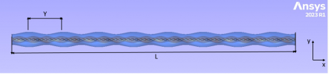
The physical model consists of the double elliptical twisted tube with a twisted tape heat exchanger, as shown in Figure 1. Depicts a basic illustration of a counter-flow heat exchanger used in this investigation. It consists of double elliptical twisted tubes of 1 m in length each. The hot fluid can pass through the inner tube, whereas cold fluid flows in the outer tube. There were (a=0.007 m), (b=0.012 m), (A=0.021) and (B=0.03) utilized for the semi-major diameter and the semi-minor diameter for inner and outer tubes respectively, a thickness of 0.004m. Twisted ratio (Tr=5) for double elliptical twisted tubes and twisted ratio for twisted tape (TR=4) were tested, and all simulations were performed for 5000≤Re≤25000.
Figure 1. A schematic illustration of the physical problem
The continuity, momentum, and energy equations are the three-dimensional governing equations for the solution of the turbulent fluid and heat transfer. Whose actualization makes use of the Cartesian coordinate system. All of the mentioned equations are listed as follows [24]:
3.1 Assumptions of flow
The steady-state turbulent flow assumptions were taken.
The following assumptions:
1. Steady-state flow
2. Turbulent flow
3. Three-dimensional flow
4. Incompressible flow
5. Body force is ignored
$\rho u+\partial / \partial v+\partial / \partial z+\rho w=0$ (1)
Momentum equations:
$\begin{aligned} \rho\left(\frac{\partial u^2}{\partial x}+\frac{\partial u v}{\partial y}+\right. & \left.\frac{\partial u w}{\partial z}\right) =-\frac{\partial p}{\partial x}+\frac{\partial}{\partial x}\left(2 \mu_{\text {eff }} \frac{\partial u}{\partial x}\right) \\ & +\frac{\partial}{\partial y}\left(\mu_{\text {eff }} \frac{\partial u}{\partial y}\right)+\frac{\partial}{\partial z}\left(\mu_{\text {eff }} \frac{\partial u}{\partial z}\right) \\ & +\frac{\partial}{\partial y}\left(\mu_{\text {eff }} \frac{\partial v}{\partial x}\right)+\frac{\partial}{\partial z}\left(\mu_{\text {eff }} \frac{\partial w}{\partial x}\right)\end{aligned}$ (2)
Energy equations:
$\begin{aligned} \rho\left(\frac{\partial u v}{\partial x}+\frac{\partial v^2}{\partial y}+\right. & \left.\frac{\partial v w}{\partial z}\right) =-\frac{\partial p}{\partial y}+\frac{\partial}{\partial x}\left(\mu_{\text {eff }} \frac{\partial v}{\partial x}\right) \\ & +\frac{\partial}{\partial y}\left(2 \mu_{\text {eff }} \frac{\partial v}{\partial y}\right)+\frac{\partial}{\partial z}\left(\mu_{\text {eff }} \frac{\partial v}{\partial z}\right) \\ & +\frac{\partial}{\partial x}\left(\mu_{\text {eff }} \frac{\partial u}{\partial y}\right)+\frac{\partial}{\partial z}\left(\mu_{\text {eff }} \frac{\partial w}{\partial y}\right)\end{aligned}$ (3)
$\begin{aligned} \frac{\partial \mathrm{uT}}{\partial \mathrm{x}}+\frac{\partial \mathrm{vT}}{\partial \mathrm{y}}+\frac{\partial \mathrm{wT}}{\partial \mathrm{z}} =\frac{\partial}{\partial \mathrm{x}}\left(\Gamma_{\text {eff }} \frac{\partial \mathrm{T}}{\partial \mathrm{x}}\right)+\frac{\partial}{\partial \mathrm{y}}\left(\Gamma_{\text {eff }} \frac{\partial \mathrm{T}}{\partial \mathrm{y}}\right) +\frac{\partial}{\partial \mathrm{z}}\left(\Gamma_{\text {eff }} \frac{\partial}{\partial \mathrm{z}}\right)\end{aligned}$ (4)
$\Gamma_{e f f}=\Gamma+\Gamma_t$ (5)
$\mu_{e f f}=\mu+\mu_t$ (6)
3.2 Turbulence model
The standard k-model is used to examine the influence of turbulence on the flow. Due to its reasonable accuracy, durability, and economy for a broad class of turbulent flows, standard k- is commonly employed in heat transfer and industrial discharges. Here are the transport equations for the standard k- model [25]:
Turbulent kinetic energy (k) equation:
$\frac{\partial}{\partial \mathrm{x}_{\mathrm{i}}}\left(\rho \mathrm{ku}_{\mathrm{i}}\right)=\frac{\partial}{\partial \mathrm{x}_{\mathrm{j}}}\left(\left(\mu+\frac{\mu_{\mathrm{t}}}{\sigma_{\mathrm{t}}}\right) \frac{\partial \mathrm{k}}{\partial \mathrm{x}_{\mathrm{j}}}\right)+\mathrm{G}_{\mathrm{k}}+\mathrm{G}_{\mathrm{b}}-\rho \varepsilon$ (7)
Turbulent energy dissipation (ɛ) equation:
$\begin{aligned} \frac{\partial}{\partial \mathrm{x}_{\mathrm{i}}}\left(\rho \varepsilon \mathrm{u}_{\mathrm{i}}\right)=\frac{\partial}{\partial \mathrm{x}_{\mathrm{j}}} & \left(\left(\mu+\frac{\mu_{\mathrm{t}}}{\sigma_{\varepsilon}}\right) \frac{\partial \varepsilon}{\partial \mathrm{x}_{\mathrm{j}}}\right) +\mathrm{C}_{1 \varepsilon} \frac{\varepsilon}{\mathrm{k}}\left(\mathrm{G}_{\mathrm{k}}+\mathrm{C}_{3 \varepsilon} \mathrm{G}_{\mathrm{b}}\right)-\mathrm{C}_{2 \varepsilon} \rho \frac{\varepsilon^2}{\mathrm{k}}\end{aligned}$ (8)
Gk and Gb are measures of the kinetic energy produced by turbulent motion due to gradients in mean velocity. The model constants C1, C2, and C3. For the diffusion of k, the corresponding turbulent Prandtl numbers are k and. Meaning of Turbulent Viscosity:
$\begin{gathered}\mu_{\mathrm{t}}=\rho \mathrm{C}_\mu \frac{\mathrm{k}^2}{\varepsilon} \\ \mathrm{C}_\mu=0.09, \mathrm{C}_{1 \varepsilon}=1.44, \mathrm{C}_{2 \varepsilon}=1.92, \sigma_{\mathrm{k}}=1, \sigma_{\varepsilon}=1.3\end{gathered}$ (9)
3.3 Data reduction
Log mean temperature difference (LMTD) for counter flow is obtained as:
$L M T D=\frac{\Delta T 1-\Delta T 2}{{In}\left(\frac{\Delta T 1}{\Delta T 2}\right)}$ (10)
$\Delta T 1=(T h i-T c o)$ (11)
$\Delta T 2=(T h o-T c i)$ (12)
The heat exchanger effectiveness is:
$\begin{aligned} \epsilon & =\frac{\mathrm{qact}}{\mathrm{qmax}} \\ \mathrm{C}_{\mathrm{h}} & =\mathrm{m}_{\mathrm{h}} \mathrm{cp} _{\mathrm{h}} \\ C_c & =m_c c p_c\end{aligned}$ (13)
The actual heat transfer is:
$\mathrm{qact}=\mathrm{C}_{\mathrm{c}}\left(\mathrm{T}_{\mathrm{ci}}-\mathrm{T}_{\mathrm{co}}\right)$
The maximum heat transfer is:
$\mathrm{qmax}=\mathrm{C}_{\min }\left(\mathrm{T}_{\mathrm{hi}}-\mathrm{T}_{\mathrm{ho}}\right)$
where, Cmin is the minimum value of Cc and Ch.
Reynolds number of the fluid in the inner:
$\begin{aligned} R_{e i} & =\frac{\rho D_{h i} V_i}{\mu} \\ \mathrm{V}_{\mathrm{i}} & =\frac{\mathrm{m}_{\mathrm{h}}}{\rho \mathrm{A}_{\mathrm{c}, \mathrm{i}}}\end{aligned}$ (14)
Reynolds number of the fluid in the outer:
$\begin{gathered}\mathrm{R}_{\mathrm{eo}}=\frac{\rho \mathrm{D}_{\mathrm{ho}} \mathrm{V}_{\mathrm{o}}}{\mu} \\ \mathrm{D}_{\mathrm{hi}}=\frac{4 \mathrm{~A}_{\mathrm{c}, \mathrm{i}}}{\mathrm{p}_{\mathrm{w}, \mathrm{i}}} \text { and } \mathrm{D}_{\mathrm{ho}}=\frac{4 \mathrm{~A}_{\mathrm{c}, \mathrm{o}}}{\mathrm{p}_{\mathrm{w}, \mathrm{o}}} \\ D_{h i}=d_i, D_{h o}=D_i-d_o\end{gathered}$ (15)
The overall heat transfer coefficient of double pipe heat exchanger
$\mathrm{U}=\frac{\mathrm{Q}_{\mathrm{avg}}}{\mathrm{A}_{\mathrm{s}, \mathrm{o}} \mathrm{LMTD}}$ (16)
where, $A_{s, o}=\pi d_o L, Q_{\text {avg }}=\frac{Q_h+Q_c}{2}$.
3.4 Boundary condition
The examined model has the following boundary conditions applied to it:
1.At the inlet: the velocity of hot water is varied, and the velocity of cold water is kept constant at (0.3026) m/s.
V hot is set as (0.0517, 1034, 0.1552, 0.2069, 0.2586) m/s.
The value of T cold is set at 298k, and the value of Thot is set at 353k.
2. No slip condition, adiabatic wall.
3. Zero relative gauge pressure is assumed at the outlets.
4.1 Convergence and coding
Numerical solutions are found for the governing equations of the present model. The Navier-Stokes equations in three dimensions can be predicted using CFD. code Fluent23. Using computational fluid dynamics (CFD) modelling, the fluid flow properties of a twisted elliptical double-tube heat exchanger can be determined at many points. The convergence criteria for the equations of motion and energy are 1*10-6.
4.2 Grid study
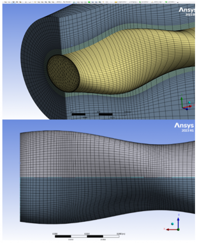
Figure 2, describes the computing grid in broad terms. Given that structured mesh provides a number of advantages over unstructured mesh, such as higher quality outcomes, faster convergence, and fewer cells, this research uses the ANSYS Meshing software to generate a structured mesh.
Figure 2. Mesh generation
The average overall heat transfer coefficient for different mesh sizes is calculated to ensure grid independence. Table 1 shows the total heat coefficient for various mesh sizes in the instance of a Double elliptical tubes heat exchanger (DETTHE) and a Reynolds number of 5000. The difference between the two successive examples is shown in the last column. This is calculated by taking the total heat coefficient for the smaller mesh size, subtracting the larger mesh size, and then dividing by the smaller number. The mesh elements increased to 5,605,207 resulting in a 4.9% inaccuracy, as seen in the table. This suggests that further refining the mesh has little effect on the total coefficient. As a result, in the previous configuration, the mesh size is proportional to the number of mesh components employed.
Table 1. Overall heat transfer coefficient for different mesh size
|
Percentage Error (%) |
Overall Heat Coefficient |
Mesh Size |
Cases |
|
….. |
2000 |
1,109,543 |
1 |
|
19.5 |
2390 |
1,678,950 |
2 |
|
7.9 |
2580 |
2,359,754 |
3 |
|
5.9 |
2733 |
3,632,131 |
4 |
|
5.3 |
2880 |
4,532,145 |
5 |
|
4.9 |
3020 |
5,605,207 |
6 |
|
3.4 |
3123 |
5,976,432 |
7 |
The results obtained from this study, including the impact of the twisting tape and twisted tubes on the thermal performance of the double elliptical twisted tubes heat exchanger, are clarified. We examined how inserting twisted tape affected heat transfer and flow by evaluating the double-twisted heat exchanger's output temperature, performance, and efficiency.
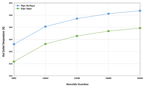
Figure 3 depicts change of the hot fluid outlet temperature with the Reynolds number for the double elliptical twisted tubes heat exchanger with a twisted tape at twisted ratio (TR=4). From the figure, it can be noted that the Tho is increased when the Re is increased due to the increase in the hot water flow velocity, which reduces the time of heat transfer exchange. When inserted, tape in the inner tube that gives the best thermal performance.
Figure 3. The hot fluid's output temperature's relationship to Reynolds number for DETTHE at TR=4
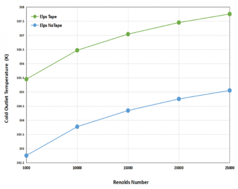
Figure 4 indicates the relation between the cold water outlet temperature and Reynolds number for DETTHE with the twisted ratio for twisted tape (TR=4). The cold water outlet temperature for the double elliptical twisted tubes with tape insert is higher than without tape. It increases when the Reynolds number increase for all cases. The increases in the Reynolds number will increase the heat energy dissipating from the inner pipe. Also, the double elliptical twisted tubes with tape have an average improvement in cold water outlet temperature (TR=4) by 0.092% over those without tape.
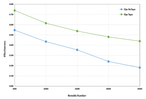
Figure 5 demonstrates the modification of the heat exchanger's effectiveness with a Reynolds number for DETTHE and the twisted ratio for twisted tape (TR=4). This graph illustrates that heat exchanger effectiveness improved with the decrease in the Reynolds number. The effectiveness of the heat exchanger improved by 36% compared with the double-twisted elliptical tubes without tape. Because the momentum of the fluid and the turbulence of the flow both increase as the double tubes are twisted, more heat is transferred from the hot fluid to the cold fluid. When determining the effectiveness of the heat exchanger, it is sufficient to divide the actual heat by the extreme heat, as the latter mostly determines the former. This diagram also shows that increased secondary flow makes the heat exchanger more efficient above the tape insert.
Figure 4. The relationship between cold fluid output temperature and Reynolds number for DETTHE at TR=4
Figure 5. Effectiveness variation against Reynolds number for DETTHE with TR=4
Figure 6 describes the relationship between the coefficient of overall heat transfer and the Reynolds number for DETTHE with the twisted ratio for twisted tape (TR=4). This figure shows that as the Reynolds number increases, so does the overall heat transfer coefficient because a big amount of heat is transported. Heat transfer is improved as the double tubes are twisted because a secondary flow is generated, drawing the fluid closer to the tube wall.
Figure 7 represents the temperature distribution in a cross-section for DETTHE _TT and D ETTHE at Different values of Reynolds number range of 5000≤Re≤25000 at axial section from the entrance. As seen in this figure, in section (a), to improve fluid mixing in the annulus, the inner twisted elliptical tube with tape insert causes the fluid to flow rotatable and procedures the secondary flow. Heat transmission is improved as the hot flow enters the tube at a lower temperature than the annular flow caused by the twist. When the twisted ratio is (TR=4), the thermal boundary layer in the inner tube wall is ruptured as a result of the higher velocity and secondary flow. This can be explained by the smaller twist ratio producing more vigorous swirl intensity, leading to more functional obstruction of the boundary layer along the flow path along the studied range of Reynolds_ number. (b) Fluid mixing is enhanced, the boundary layer is disturbed, and the thickness is significantly reduced in double-twisted elliptical tubes with a twisted ratio of (Tr=5).
Figure 6. Variation of the coefficient of overall heat transfer versus Reynolds number for DETTHE with TR=4
Figure 7. Cross-section temperature contour at x=0.2, x=0.5, x=0.8 and x=0.9m (a) twisted tubes with tape, (b) twisted tubes without tape at Re=5000
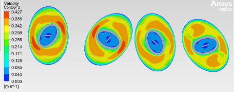
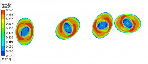
Figure 8 depicts the velocity distribution at different cross sections for D ETTHE and D ETTHE -TT at Different value of Reynolds number of 5000≤ Re ≤ 25000 at axial section from the entrance (x=0.2, 0.5, 0.8, 0.9). The velocity is lowest at the region nearest the tube wall, where the shear stress is greatest, and highest in the middle of each cross-section. The DCTTHE-TT velocity curves show increased speed around the tube's center. When the twisted tape is put into the inner tube, the flow is mixed, disrupting the boundary layer's formation and decreasing its thickness.
Figure 8. Cross-section velocity contour at x=0.2, x=0.5, x=0.8, x=0.9m (a) twisted tubes with tape, (b) twisted tubes without tape at Re=5000
This work presents a numerical study demonstrating the impact of twisted elliptical tubes with a twisted tape on the performance of a double-tube heat exchanger. The most important findings are summed up as follows:
1- At TR=4, the double twisted elliptical tubes exceeded the plain tube in terms of the overall heat transfer coefficient with insert twisted tape.
2- Inserting a twisted tape within DETTHE twisted the inner tube and enhanced fluid mixing in the tubing annulus, facilitating the flow redirection from the core region to the heat.
3- It was found that twisting the elliptical tube improved the heat transfer coefficient at higher Reynolds numbers.
4- When the Reynolds number of 5000, the effectiveness of the double tubes heat exchanger rises by 75 %.
5- The minimum value of the twisted ratio of twisted tubes Tr=5 significantly improves heat transmission more than that of Tr=10 and Tr=15.
The author would like to thank to my dear supervisor Prof. dr. Khudheyer S. Mushatet, Professor of heat transfer in the department of mechanical Engineering College of Engineering, University of Thi-Qar.
|
a |
Minor diameter of inner tube,m |
|
b |
Major diameter of inner tube, m |
|
A |
Minor diameter of outer tube, m |
|
B |
Major diameter of outer tube, m |
|
L |
Length of double twisted tubes, m |
|
Cp |
Specific heat (J/kg .K) |
|
di |
Inner diameter of the inner tube (m) |
|
Dh |
Hydraulic diameter (m) |
|
Thi |
Hot fluid inlet temperature (K) |
|
Tho |
Hot fluid outlet temperature (K) |
|
Tci |
Cold fluid inlet temperature (K) |
|
Tco |
Cold fluid outlet tempe rature (K) |
|
Re |
Reynolds number of the fluid |
|
Y |
Pitch length of twisted tube, m |
|
Abbreviations |
|
|
DTTHE |
Double Twisted tubes Heat Exchanger |
|
DETTHE |
Double elliptical Twisted tubes Heat Exchanger |
|
DETTHE-TT |
Double elliptical Twisted tubes Heat Exchanger-Twisted Tape |
|
LMTD |
Log Mean Deference Temperature |
|
Greek symbols |
|
|
ρ |
Density (kg/m3) |
|
ϵ |
Effectiveness |
|
μ |
Dynamic viscosity (kg /m s) |
[1] Razzaq, A.K.A., Mushatet, K.S. (2023). Numerical prediction for turbulent flow and heat transfer in elliptical twisted tube. In 6th ASIA PACIFIC International Modern Sciences Congress, Delhi, India. https://www.kongreuzmani.com.
[2] Safikhani, H., Abbasi, F. (2015). Numerical study of nanofluid flow in flat tubes fitted with multiple twisted tapes. Advanced Powder Technology, 26(6): 1609-1617. https://doi.org/10.1016/j.apt.2015.09.002
[3] Mushatet, K.S., Rishak, Q.A., Fagr, M.H. (2020). Experimental and numerical investigation of swirling turbulent flow and heat transfer due to insertion of twisted tapes of new models in a heated tube. Applied Thermal Engineering, 171: 115070. https://doi.org/10.1016/j.applthermaleng.2020.115070
[4] Luo, C., Song, K., Tagawa, T. (2021). Heat transfer enhancement of a double pipe heat exchanger by Co-Twisting oval pipes with unequal twist pitches. Case Studies in Thermal Engineering, 28: 101411. https://doi.org/10.1016/j.csite.2021.101411
[5] Wu, C.C., Yang, Y.T., Huang, K.H. (2018). Numerical simulation of turbulent flow forced convection in a twisted elliptical tube. International Journal of Thermal Sciences, 132: 199-208. https://doi.org/10.1016/j.ijthermalsci.2018.05.028
[6] Cheng, J., Qian, Z., Wang, Q. (2017). Analysis of heat transfer and flow resistance of twisted oval tube in low Reynolds number flow. International Journal of Heat and Mass Transfer, 109: 761-777. https://doi.org/10.1016/j.ijheatmasstransfer.2017.02.061
[7] Mashayekhi, R., Eisapour, A.H., Eisapour, M., Talebizadehsardari, P., Rahbari, A. (2022). Hydrothermal performance of twisted elliptical tube equipped with twisted tape insert. International Journal of Thermal Sciences, 172: 107233. https://doi.org/10.1016/j.ijthermalsci.2021.107233
[8] Kim, H.R., Kim, S., Kim, M., Park, S.H., Min, J.K., Ha, M.Y. (2016). Numerical study of fluid flow and convective heat transfer characteristics in a twisted elliptic tube. Journal of Mechanical Science and Technology, 30: 719-732. https://doi.org/10.1007/s12206-016-0127-4
[9] Alempour, S.M., Abbasian Arani, A.A., Najafizadeh, M.M. (2020). Numerical investigation of nanofluid flow characteristics and heat transfer inside a twisted tube with elliptic cross section. Journal of Thermal Analysis and Calorimetry, 140: 1237-1257. https://doi.org/10.1007/s10973-020-09337-z
[10] Mushatet, K.S., Hmood, H.M. (2021). Numerical investigation for heat transfer enhancement in a triangular twisted tube. ARPN Journal of Engineering and Applied Sciences, 16(5): 593-599.
[11] Salam, B., Biswas, S., Saha, S., Bhuiya, M.M.K. (2013). Heat transfer enhancement in a tube using rectangular-cut twisted tape insert. Procedia Engineering, 56: 96-103. https://doi.org/10.1016/j.proeng.2013.03.094
[12] Murali, G., Nagendra, B., Jaya, J. (2020). CFD analysis on heat transfer and pressure drop characteristics of turbulent flow in a tube fitted with trapezoidal-cut twisted tape insert using Fe3O4 nano fluid. Materials Today: Proceedings, 21: 313-319. https://doi.org/10.1016/j.matpr.2019.05.451
[13] Mushatet, K.S., Youssif, F.K. (2018). Prediction the thermal and hydrodynamic performance of nano fluids flow in a tube coupled with double twisted tape. Arpn Journal of Engineering and Applied Sciences, 13: 12.
[14] Razzaq, A.K.A., Mushatet, K.S. (2021). Evaluation the performance of the double tube heat exchanger by using combined twisted tube and nano fluid. International Journal of Mechanical Sciences, 7(1): 6618-6628.
[15] Singh, S.K., Sarkar, J. (2021). Hydrothermal performance comparison of modified twisted tapes and wire coils in tubular heat exchanger using hybrid nanofluid. International Journal of Thermal Sciences, 166: 106990. https://doi.org/10.1016/j.ijthermalsci.2021.106990
[16] Li, X., Wang, L., Feng, R., Wang, Z., Zhu, D. (2021). Thermal-hydraulic characteristics of twisted elliptical tube bundle in staggered arrangement. Journal of Thermal Science, 30(6): 1925-1937. https://doi.org/10.1007/s11630-021-1450-3
[17] Karimi, A., Al-Rashed, A.A., Afrand, M., Mahian, O., Wongwises, S., Shahsavar, A. (2019). The effects of tape insert material on the flow and heat transfer in a nanofluid-based double tube heat exchanger: Two-phase mixture model. International Journal of Mechanical Sciences, 156: 397-409. https://doi.org/10.1016/j.ijmecsci.2019.04.009
[18] Mushatet, K.S., Youssif, F.K. (2018). Modeling whirling motion and heat transfer intensification in a heated tube with a twin twisted tape. In 2018 International Conference on Advance of Sustainable Engineering and its Application (ICASEA), pp. 215-220. https://doi.org/10.1109/ICASEA.2018.8370984
[19] Nakhchi, M.E., Esfahani, J.A. (2021). Numerical investigation of turbulent CuO–water nanofluid inside heat exchanger enhanced with double V-cut twisted tapes. Journal of Thermal Analysis and Calorimetry, 145: 2535-2545. https://doi.org/10.1007/s10973-020-09788-4
[20] Hussein, B.A., Mushatet, K.S. (2019). Enhancing heat transfer by using combined conical turbulators and swirling tapes. University of Thi-Qar Journal for Engineering Sciences, 10(1): 43-49. https://doi.org/10.31663/tqujes.10.1.351(2019)
[21] Mushatet, K.S., Rishak, Q.A., Fagr, M.H. (2019). Study of enhancing thermo-hydraulic performance of turbulent flow inside a tube occupied with central cut twisting tapes. University of Thi-Qar Journal for Engineering Sciences, 10(2): 52-63. https://doi.org/10.31663/tqujes.10.2.318(2019)
[22] Razzaq, A.K.A., Mushatet, K.S. (2023). A Review study for a twisted tube heat exchanger. Journal of Nanofluids, 12(2): 299-317. https://doi.org/10.1166/jon.2023.1926
[23] Mushatet, K.S., Youssif, F.K. (2018). Prediction the thermal and hydrodynamic performance of nano fluids flow in a tube coupled with double twisted tape. Arpn Journal of Engineering and Applied Sciences, 13: 12.
[24] Talebi, M., Lalgani, F. (2021). Assessment of thermal behavior of variable step twist in the elliptical spiral tube heat exchanger. International Journal of Thermal Sciences, 170: 107126. https://doi.org/10.1016/j.ijthermalsci.2021.107126
[25] Cable, M. (2009). An evaluation of turbulence models for the numerical study of forced and natural convective flow in Atria. Doctoral Dissertation, Queen's University.