Farhan Lafta Rashid![]() | Ali Basem
| Ali Basem![]() | Mudhar A. Al-Obaidi*
| Mudhar A. Al-Obaidi*![]() | Sarah Abbas Jawad
| Sarah Abbas Jawad![]() | Ahmed Kadhim Hussein
| Ahmed Kadhim Hussein![]() | Bagh Ali
| Bagh Ali![]() | Mohamed Bechir Ben Hamida
| Mohamed Bechir Ben Hamida![]()
© 2023 IIETA. This article is published by IIETA and is licensed under the CC BY 4.0 license (http://creativecommons.org/licenses/by/4.0/).
OPEN ACCESS
The optimisation of heat transfer, which is the transition of thermal energy from regions of high temperature to those of lower temperature, is a cornerstone in the field of thermal sciences and engineering. It is of vital importance to maximise energy efficiency, ensure system performance, and uphold operational reliability across numerous industrial applications. In this context, recent investigations have explored the modification of heat transfer rates through the turbulence induced by air-bubble injections. The technique has found application in heat exchangers, solar stills, and solar collectors, where it can be employed to either augment or attenuate heat transmission. The majority of the research has been dedicated to enhancing thermal efficiency, with both theoretical models and experimental data underpinning our current understanding. This review provides a critical analysis of over 45 studies from the literature, which have examined the implications of air bubble injection across various realms of industry, including heat exchangers, water desalination systems, solar collectors, and diverse media. Our analysis underscores the profound impact of heat transfer rates on process productivity, efficiency, and cost-effectiveness across a gamut of applications. A range of industrial processes, such as cooling, heating, evaporation, and condensation, all rely heavily on efficient heat exchange. Enhancements in heat transfer rates hold the potential to curtail energy losses, reduce fuel consumption, and subsequently lower operational costs in industrial applications like solar thermal systems. Moreover, efficient heat transfer is pivotal in minimising temperature variations, thereby contributing to consistent outcomes.
air bubble injection, heat exchanger, solar water collector, solar still
The enhancement of heat transmission, a pivotal facet of engineering and thermal sciences, significantly impacts a multitude of industrial sectors. The efficient exchange of heat is essential for the optimal operation of systems, improved performance, and production of consistent results. This concept is integral for achieving sustainable, reliable, and resource-efficient practices in diverse industrial applications, from enhancing energy efficiency and temperature control to progressing renewable energy, manufacturing techniques, and electronics cooling.
The regulated injection of air bubbles can greatly benefit a myriad of applications. Its utility extends across sectors such as wastewater treatment, pharmaceuticals, food processing, and environmental remediation, serving various functions [1, 2]. These include improving mass transfer and mixing, aiding flotation and particle separation, facilitating aeration for biological treatments, and simplifying gas-liquid reactions [3]. Thus, air bubble injection is instrumental in augmenting process effectiveness, enhancing product quality, and enabling environmentally sustainable solutions across a broad spectrum of industrial and scientific fields.
The technique of air bubble injection has recently been examined extensively, both computationally and experimentally, because of its application in various fields [4-9]. Notably, it has been employed in solar technologies such as solar water collectors, heat exchangers, and distillers. The disruption of fluid flow through the injection of air bubbles has been identified as an effective method of heat transfer in these applications. Specifically, air injection technology has been implemented in a range of applications, predominantly in vertical, spiral, and horizontal pipe designs [10-13].
Concentrate tube heat exchangers, due to their simple design and ease of fabrication, are widely employed in heat transfer applications. Li et al. [14] provided a comprehensive review of the enhancement of heat transfer and flow characteristics in these heat exchangers, primarily focusing on double and triple concentric pipe designs. Mohiuddin et al. [15] discussed significant past and recent internal modifications to increase distillate production, with particular reference to phase change materials (PCMs) which were found to increase distillate output by up to 80%. Given the observed deficiency in distillate production, researchers are necessitated to undertake further modifications aimed at augmenting productivity. This has culminated in the exploration of contemporary internal designs. Six key sub-sections of recent internal modifications are identified: fins, wicks, nano fluids, nanostructures, dynamic changes, and natural materials. Among the dynamic changes, the spinning wick solar still stands out with a substantial 300% productivity enhancement, demonstrating a maximum cumulative production of 8.78 kg/m2 day compared to the 2.21 kg/m2 day offered by the conventional solar still (CSS).
Ahmed et al. [16] offered an insightful description of the most prevalently deployed solar water heating apparatus. Their critical focus was centered on current technological advancements, encompassing storage tank/integrated collector storage solar water heaters, active and passive solar water heaters, concentrated and non-concentrated solar thermal collectors, and various governing laws. To augment overall performance, exhaustive experimental and research work has been conducted, implementing appropriate technologies that include optimal designs, geometric alterations, and simulation work. Furthermore, the impact of solar collectors, radiation, geography, water tank temperature, experimental modeling/simulation, and ongoing research in Asia, America, and Europe on solar water heating systems (SWHS) are all important aspects warranting consideration.
Owing to the extensive deployment of air bubble injection across numerous sectors and scientific disciplines, it is imperative to comprehend its effects. The introduction of air bubbles exerts a significant influence on a multitude of processes. Therefore, it is crucial to understand the dynamics of air bubbles in diverse media, their interactions with particles, and the consequent effects on mixing, mass transfer, and reaction kinetics. To foster progress in this field, a thorough review of relevant works is required. Providing a synthesis of the existing knowledge not only elucidates the complexities of air bubble behavior, bubble-particle interactions, and bubble size distribution, but also identifies knowledge gaps, proposes innovative methodologies, and facilitates the creation of predictive models. Despite the widespread application of air bubble injection, a comprehensive review assessing its influence across various industrial applications remains to be conducted. The present study aims to address this by offering a comprehensive evaluation of the application of air bubble injection for enhancing heat transfer across a variety of industrial scenarios. Specifically, this research seeks to demonstrate the maturity and evolution of air bubble injection in heat exchangers, water desalination systems, and solar collectors, based on a comprehensive review of the associated studies. Furthermore, this research aims to explore considerations for improving the integration of air bubble injection in different media.
Heat exchangers are mechanical devices with the primary purpose of transferring (exchanging) heat from one fluid to another. Because of its small size, ease of manufacture, and high heat transfer efficiency, shell and helical coiled tube heat exchangers are the most well-known heat exchangers. The incorporation of air bubble injection in heat exchanger in actual applications has been articulated by several colleagues as discussed below.
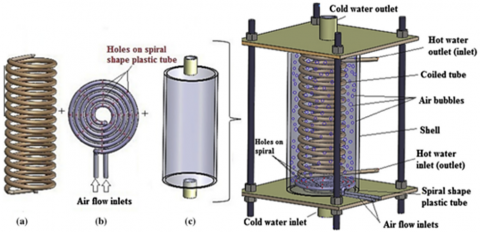
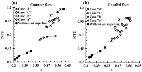
By injecting air bubbles into the shell side of a vertical shell and coiled tube heat exchanger, Dizaji et al. [17] enhanced the performance and number of thermal units (NTU). Figure 1 shows the air bubbles injected method through the heat exchanger. Undeniably, air bubble injection and bubble mobility (owing to buoyancy force) can worsen the NTU by mixing the thermal boundary layer and boosting the turbulence level of the fluid flow. Figure 2 shows the improvement of NTU and efficacy due to injecting air bubbles injection in counter flow and parallel flow.
Figure 1. Vertical shell and coiled tube heat exchanger and air bubble injection system [17]
Figure 2. Relationship between ε and NTU for (a) counter flow and (b) parallel flow [17]
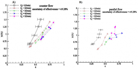
The influence of air bubble injection on the performance of a horizontal helical shell and coiled tube heat exchanger were investigated experimentally by Khorasani and Dadvand [18]. In this regard, the influences of variable air flow rates on NTU, exergy loss, and efficacy were examined. Figure 3 specifies significant increases in the heat exchanger's efficacy and NTU as a result to injecting the air bubbles. It is fair to admit that the migration of air bubbles has enhanced the disruption and the instability strength of the shell side flow. This in turn has resulted in an increase in exergy loss and NTU. Furthermore, the bubbles' mixing impact and connectivity to the thermal boundary layer can raise the velocity (and consequently the Reynolds number (Re)) of the shell side flow.
Figure 3. Influence of ɛ on NTU at different air flow rates for the counter flow (A) and (B) parallel flow configurations [18]
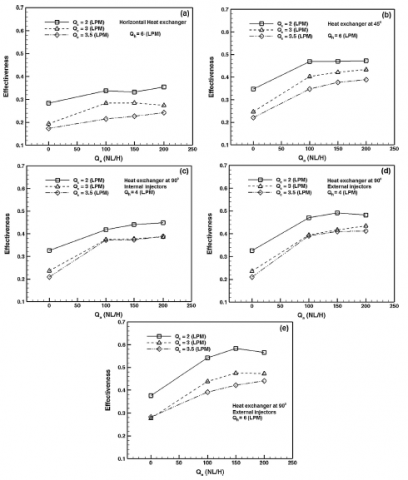
Heyhat et al. [19] investigated the influence of air bubble injection on the thermal performance of a twin pipe heat exchanger. A schematic diagram of the test rig of different injectors pump air bubbles into the annulus side is depicted in Figure 4. The experiments were carried out considering variable tube and annulus side flow rates. Figure 5 presents the influence of air flow rate and heat exchanger placement angle on heat transfer coefficient ratios. Exergetic evaluation was utilised to study the influence of air flow rate and heat exchanger placement angle on the thermal efficiency. The total heat transfer coefficient has been enhanced from 10.3% to 149.5% by the injection of air bubbles.
Figure 4. A schematic diagram of the test rig [19]
(a) Qh = 6 LPM of horizontal heat exchanger
(b) Qh = 6 LPM of heat exchanger at 45⁰
(c) Qh = 4 LPM of vertical heat exchanger with internal air injection
(d) Qh = 4 LPM of vertical heat exchanger with external air injection
(e) Qh = 6 LPM of vertical heat exchanger with external air injection
Figure 5. Influence of air flow rate and heat exchanger placement angle on heat transfer coefficient ratios [19]
Figure 6. A schematic diagram of the experimental gadget [20]
Figure 7. Influence of the shell side water flow rates on overall heat transfer coefficient at variable air flow rate [20]
Figure 8. A schematic diagram of the experimental setup [21]
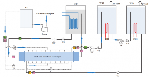
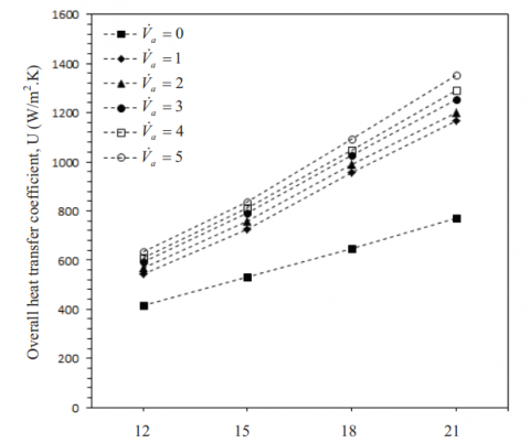
El-Said and Abou Alsood [20] explored the possibility of improving the thermal performance by utilising an air injection into the shell side of a shell-and-multi-tube heat exchanger. Figure 6 presents a schematic diagram of the experimental set-up. Air was injected into the heat exchanger shell in two ways (cross injection from the shell wall and parallel injection from the shell front side) with varied air flow rates to establish the best efficiency. With a constant tube side water flow rate, the air and shell side water flow rates were adjusted between 1-5 L/min and 12-21 L/min, respectively. According to the findings, the injected air flow rate and injection mechanism have a substantial influence on heat exchanger efficiency. Figure 7 indicates the improvement of overall heat transfer coefficient due to growing the shell side water flow rate and air flow rate.
Khorasani et al. [21] evaluated the consequence of different air volume fractions (VF) on the pressure drop and NTU using the experimental setup shown in Figure 8. The influences of air bubble injection are investigated using the second law of thermodynamics. The findings of Figure 9 elaborated that injecting air bubbles into the coil side would enhance the heat exchanger's thermal properties. It was also stated that increasing VR is important to improve the overall efficiency. Accordingly, it has been revealed that injecting air bubbles into the coil side is an efficient way for heat exchangers with elevated liquid flow rates.
Figure 9. Influence of air injection into the coiled tube on entropy generation number at different water flow rate [21]
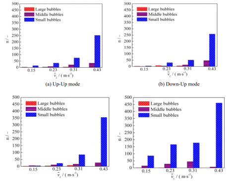
Li et al. [22] investigated the impact of employing a combination of air and water as the cold flow medium in a plate heat exchanger. A schematic diagram of an experimental bench sketch is presented in Figure 10. Li et al. [22] considered alternative fluid intake and output port locations. The heat transmission efficiency is ascertained to be proportional to the movement of air bubbles in the cold flow. The results demonstrated that a quicker flow velocity of air and water combination has bigger Froude number (Fr), Re, Weber number (Wn), and smaller bubble size, besides a greater sectional void percentage on the top portion of the channel, independent of the intake and exit ports for the fluid. However, the fluid input and exit locations have a significant impact on the bubble distribution, indicating that bubble buoyancy has a significant impact on the bubble distribution. This is already demonstrated in Figure 11.
Figure 10. A schematic diagram of an experimental bench sketch [22]
Figure 11. Bubble quantity changing with the liquid velocities in different fluid inlet/outlet modes [22]
Figure 12. A schematic diagram of coaxial heat exchanger [23]
Figure 13. Water temperature profiles in the radial direction [23]
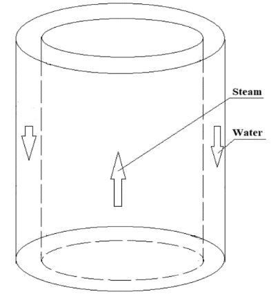
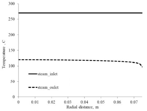
Akhmadullin and Kartushinsky [23] carried out a numerical examination of a two-phase bubbly flow within a long vertical counter flow heat exchanger. Figure 12 shows a schematic diagram of coaxial heat exchanger. The heat is transferred from the steam within the tube to the two-phase bubbling water in the annulus. In a large-scale unit, the optimal computing approach is a two-dimensional steady-state heat transfer and fluid flow model based on the coupling of a probability density function (PDF) connected to a k-epsilon turbulence model. Akhmadullin and Kartushinsky [23] looked at two scenarios: A short (800 m) and a long heat exchanger (8000 m). In the radial direction, flow velocities, pressure, temperature, and bubble concentration were all within allowable boundaries, as depicted in Figures 13-16. The findings supported the validity of the gathered data by providing a consistency between the theoretical and experimental outcomes.
Figure 14. Distribution of steam axial velocity [23]
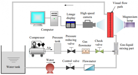
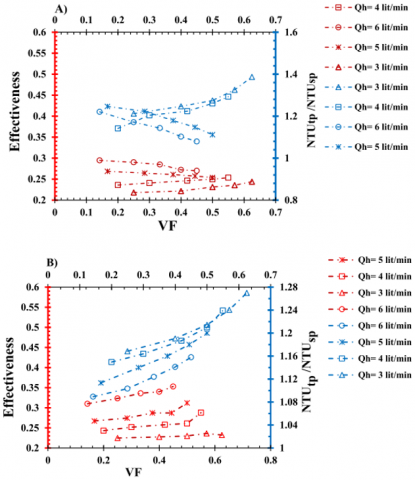
Sinaga et al. [24] investigated experimentally a double tube heat exchanger with two-phase air/water flow via the inner tube. The experimental apparatus is illustrated in Figure 17. Air and hot water were combined at a T-junction outside the heat exchanger and then passed through the inner tube. The cold water flow rate was maintained constant at 2 L/min. Four alternative flow rates of hot water were considered: 3, 4, 5, and 6 L/min. Moreover, the entrance temperatures of hot and cold water streams were nearly consistent, ranging between 17℃ to 19℃ and 48℃ to 50℃, respectively. In addition, five alternative air flow rates of 1, 2, 3, 4, and 5 L/min were evaluated. Figure 18 shows that the heat transfer coefficient has increased by 33% and the number of transfer units has increased by 38%. The Witte-Shams under efficiency factor reached its peak value of 0.973 at counter flow, which corresponded to a 0.57 vol.%.
Figure 15. Distribution of water velocity in the annulus [23]
Figure 16. Distribution of steam temperature at the inlet and outlet of the long pipe [23]
Figure 17. A schematic diagram of the experimental setup [24]
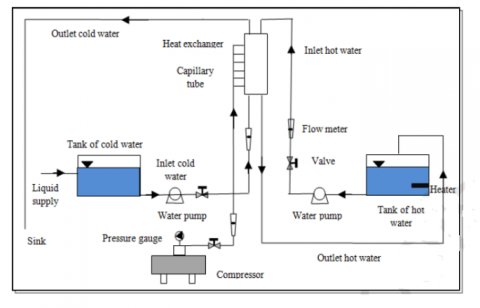
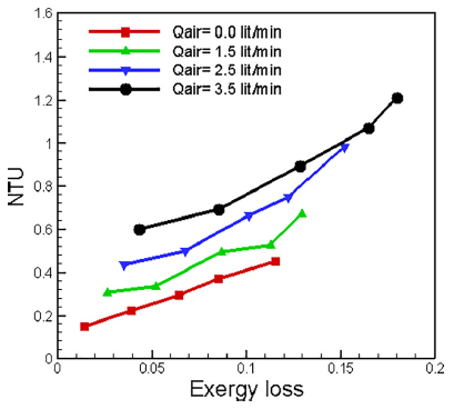
Ghashim and Flayh [25] appraised the impact of air bubble injection on heat transfer enhancement and turbulent flow pressure decrease in a two-helical coil heat exchanger. Figure 19 displays the heat exchanger arrangement. The experiment was conducted for turbulent flow with 9000 to 50000 of Re of hot water and a fixed mass flow rate of 0.0331 kg/s of cold water. Injection of air bubbles in hot water at different flow rates of 1.5, 2.5, and 3.5 L/min. Figures 20 and 21 show the experimental findings of Nusselt number (NU), effectiveness (ε), NTU, and exergy losses. Clearly, it can be demonstrated that the NU has increased from 64% to 126% and the friction factor increased from 66% to 85% for the specific range of Re between 9000 to 50000. This is attributed to the existence of air bubbles in hot water. Accordingly, it can be stated that the heat transfer has been enhanced due to bubbles injection as illustrated by an increase of thermal enhancement factor from 1.13 to 1.29 with a mass flow rate of hot water of 0.0163 kg/s and a range between 1.5 to 3.5 L/min of air bubble. However, the bubbles injection has increased the friction factor as a penalty.
Figure 18. Variation of effectiveness and NTUtp/NTUsp in terms of VF for: (A) counter flow and (B) parallel flow [24]
Figure 19. A schematic diagram of the heat exchanger system [25]
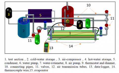
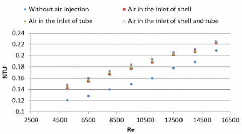
Rashid et al. [26] conducted an experimental study to evaluate the heat transfer and exergy analysis with and without injecting a 3 mm diameter air bubble at the intake of different types heat exchanger of tube, shell, and tube and shell. Figure 22 shows the experimental arrangement. The results indicate that heat exchanger with injected air bubbles has a higher NU than those without with injected air bubbles. Specifically, the NU increases from 2.13% to 25.18% when utilising the bubble injection via both shell and tube. At a Re=15000, an air bubble was injected into both the shell and tube intakes to obtain the maximum NTU. Figure 23 presents the improvement of NU as a result to increasing the Reynolds. Also, a clear improvement of NU is ascertained due to injecting air bubbles into the intake of both shell and tube compared to only injecting air bubbles into the shell or tube. Accordingly, Rashid et al. [26] estimated that the heat transfer gains associated with both tube and shell and only shell are 8.31% and 13.50%, respectively.
Table 1 summarises the associated studies that utilised the air bubble injection into the heat exchanger of different applications with highlighting the most important findings.
Table 1. A summary of relative studies that investigated the utilization of air bubble injection in the heat exchanger of different applications
|
References |
Configuration |
The Main Considered Parameters |
Study Type |
Highlighted Results |
|
Dizaji et al. [17] |
Vertical shell and coiled tube heat exchanger. |
The effects of air bubble injection on NTU, heat exchanger performance, and exergy loss are examined. |
Experimental |
|
|
Khorasani and Dadvand [18] |
Horizontal helical shell and coiled tube heat exchanger. |
NTU, exergy loss and effectiveness. |
Experimental |
|
|
Heyhat et al. [19] |
Double Pipe Heat Exchanger. |
Exergetic analysis is used to study the impact of air flow rate and heat exchanger placement angle on thermal performance. |
Experimental |
|
|
El-Said and Abou Alsood [20] |
Horizontal Shell and Multi-Tube Heat Exchanger with Baffles. |
By monitoring the pressure loss caused by the injection of air bubbles between the shell side exit and intake, the power loss in heat exchangers under the enhancement technique was ascertained. |
Experimental |
|
|
Khorasani et al. [21] |
Shell and coiled tube heat exchanger. |
VF and pressure drop are explored in relation to NTU and VF. The second rule of thermodynamics is also used to explore the effects of air bubble injection. |
Experimental |
|
|
Li et al. [22] |
Dimple-type embossing plate heat exchanger. |
Re, Fr, and Wn. |
Experimental |
|
|
Akhmadullin and Kartushinsky [23] |
Two helical coils heat exchanger. |
NU, effectiveness, NTU and exergy losses. |
Experimental |
|
|
Sinaga et al. [24] |
Long coaxial heat exchanger. |
Flow velocities, pressure, temperature, and concentration of the bubbles in the radial direction. |
Numerical (CFD) |
|
|
Ghashim and Flayh [25] |
Double tube heat exchanger. |
Pressure drop, effectiveness, NTU, heat transfer coefficient, dimensionless exergy loss and Witte-Shams under efficiency factor. |
Experimental |
|
|
Rashid et al. [26] |
Double pipe heat exchanger. |
NTU, NU, heat transfer improvements. |
Experimental |
|
Figure 20. Variation of NTU versus exergy loss for different air bubbles [25]
Figure 21. Variation of NTU versus effectiveness for different air bubbles [25]
Figure 22. A schematic diagram of the experimental setup [26]
Figure 23. Enhanced NU against Re [26]
Desalination systems based on renewable energy are long-term solutions for freshwater production. Membrane and thermal technologies are the two types of desalination procedures [27]. In comparison to other thermal desalination methods, solar is still a simple thermal desalination technique in terms of construction, operation, and repairs. Many researchers have employed air injection to increase the efficiency of desalination systems. The most successful studies are discussed below.
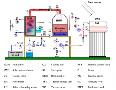
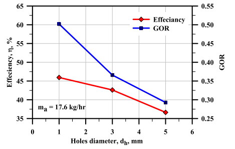
Khalil et al. [28] investigated the desalination performance of a solar water desalination system in terms of air flow rate, water temperature, water height, and sieve hole diameter. A schematic diagram of the experimental set-up is shown in Figure 24. The features of the created bubbles are varied using various sieve plates with varying hole sizes. The efficiency, daily productivity, and gain output ratios (GORs) were found to be 63%, 21 kg, and 0.53, respectively, at a temperature of 62℃ in the inflow water. All measurements showed a temperature differential of less than 2.5℃ along the column. Figure 25 shows the effect of sieve plate diameter holes on water productivity, performance, and GOR. Figure 25 introduces the highest desalination performance and GOR using a sieve of a 1 mm hole diameter and constant saturation of the exit air from the bubble columns. The act of the air bubble column overtakes that of an old-fashioned humidifier.
Figure 24. A schematic diagram of the experimental apparatus [28]
Figure 25. Influence of diameter holes of sieve plate on effectiveness and GOR [28]
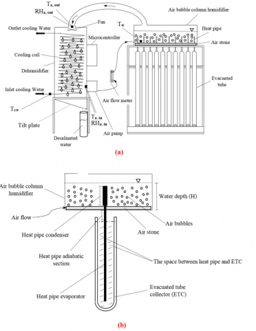
Figure 26. Schematic diagrams of (a) the experimental setup, (b) the ETCs and heat pipes [29]
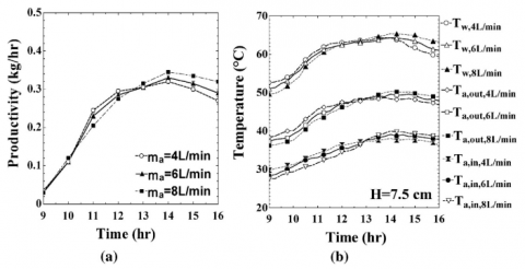
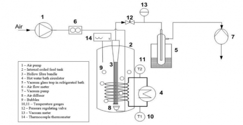
The efficiency of a unique humidification and dehumidification (HDH) solar desalination system with a combination of heat pipe (HP), evacuated tube collector (ETC), and air bubble column humidifier was examined by Behnam and Shafii [29]. Schematic diagrams of the experimental set-up and ETCs and heat pipes are shown in Figure 26. On system performance, the impacts of entering air flow rate into the humidifier, starting water depth in the humidifier, and adding fluids such as water and oil in the space between the heat pipes and ETCs were explored. The addition of oil in the gap greatly increased product water per day and efficiency to 6.275 kg/m2 day and 65%, respectively. Figure 27 presents a marginal improvement of water productivity due to increasing the air flow rate.
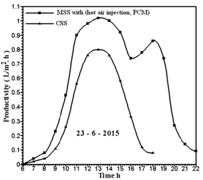
PCM is employed in the solar still as a heat storage material to increase the solar still's freshwater production. Kabeel et al. [30] looked at how injected hot air would affect the efficiency of an improved solar still with PCM. Figure 28 presents a double passes solar air collector–integrated to an adapted solar still with PCM and conventional solar still (CSS). To assess the improvement in freshwater productivity, a judgement between an adapted solar still with both PCM and hot air injection and a CSS was made. The drinking water productivity of adapted system was around 9.36 L/m2 day compared to 4.5 L/m2 day for the traditional solar still. Figure 29 shows the variation of water productivity against the operational time. Clearly, it can be stated that the double passes solar air collector linked modified solar still with PCM has a greater productivity of 108% if compared to the conventional solar still.
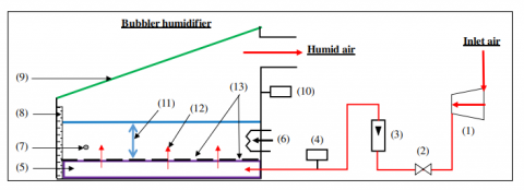
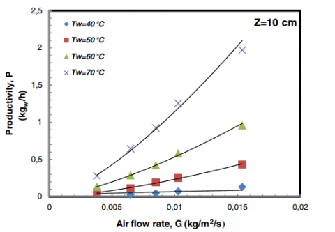
The effect of transporting air bubbles via the base of the basin of a bubble humidifier to seawater was investigated by Halima et al. [31] under different operational situations of airflow rate, input air temperature and humidity, water temperature and depth. The experimental apparatus is schematically represented in Figure 30. Within the study boundaries, the water vapor content difference is significantly influenced by water temperature and airflow velocity, but only minimally by water level. Specifically, heat and mass transport coefficients were experimentally determined using empirical correlations. Figure 31 depicts the improvement of water productivity in the bubbler basin due to increasing the air mass flow rate and water temperature.
Figure 27. Variations of (a) productivity and (b) air and water temperatures for variable air flow rates into the humidifier [29]
Figure 28. A schematic diagram of the double passes solar air collector–coupled modified solar still with PCM and conventional solar still [30]
Figure 29. Change of drinking water productivity for a modified solar still MSS with PCM, and hot air injection and CSS [30]
(1) Compressor; (2) Control valve; (3) Airflow meter; (4, 10) Thermo-hygrometer; (5) Air diffuser; (6) Electric heater; (7) Thermometer-Pt100; (8) Graduate level; (9) Transparent cover; (11) Water level; (12) Air stream; (13) Air diffuser orifices
Figure 30. Experimental setup [31]
Arunkumar et al. [32] used carbon impregnated foam (CIF) insulation and bubble-wrap (BW) insulation to develop and build a single slope solar still (SSSS) of water desalination for better fresh water productivity. Figure 32 shows a schematic diagram of the four tested structures. The solar water desalination system is a 0.50 m2 of SSSS. To systematically evaluate the efficiency of the new desalination system, the performance of four similar structures including SSSS without insulation, SSSS with BW insulation, SSSS-CIF with BW insulation, and conventional solar still (CSS) insulated with sawdust was assessed under the same climatic circumstances. The CIF was permitted to float on the water surface with a diameter of 0.17 m and a thickness of 0.015 m. The drinking water productivity of the SSSS without insulation, SSSS with BW insulation, SSSS-CIF with BW insulation, and CSS with sawdust insulation, respectively, was found to be 1.9 L/ m2 day, 2.3 L/ m2 day, 3.1 L/m2 day, and 2.2 L/ m2 day.
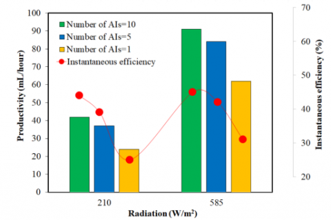
Fallahzadeh et al. [33] used a closed-loop pulsing heat pipe (CLPHP) to maximise heat transmission and decrease vapor condensation heat loss in a solar still under specified outdoor and interior settings as shown in Figure 33. The solar still comprises a single spiral collector (SSC), a bubble injection system to boost evaporation rate, and a copper tube coil (CTC) system to improve water condensation as illustrated in Figure 34. The daily production of the solar still under study was 2236 mL/day (m2 day). This can be conducted using the optimal water depth of 5 cm in the basin, which is the same length as the CLPHP condensation section. Figure 35 identifies the necessity to deploy a higher number of air injectors (AIs) to enhance the instantaneous efficiency and water productivity.
Figure 31. Influence of air flow rate on the water productivity at various water temperature [31]
Figure 32. [A] SSSS without insulation, [B] SSSS with BW insulation, [C] SSSS-CIF with BW insulation, and [D] conventional solar still [32]
Figure 33. A schematic diagram of the experimental set-up [33]
Figure 34. SSC [33]
Figure 35. Influence of the radiation and number of AIs on the solar still performance [33]
For their simulation of rising air bubbles in a liquid of varying salinity, Rashid et al. [34] used the 2-D Volume of Fluid (VOF) approach and the CFD methodology. Hydrodynamics of rising air bubbles in a liquid water column are simulated using User Defined Function (UDF) code written in the C++ environment, which makes use of the dynamic meshing approach. There has been some thought given to the possibility of air bubbles rising through a layer of still water. The data acquired demonstrated that larger bubbles result in a faster bubble's ascent. Because of the influence of different drag forces, the bubble forms shift as the diameter changes. As the Reynolds number rises from 20 to 1475, the drag coefficient drops from 2.85 to 0.4. When the Eötvös number is raised from 700 to 950, the maximum rising velocity increases by 75%, and when the bubble size is raised from 5 to 7 mm, Wn rises by 60%.
In a summary, Table 2 provides an overview of the most relevant studies that employed the air bubble injection in water desalination systems with highlighting the most important findings.
Table 2. A summary of relative studies of air bubble injection in water desalination systems
|
References |
Configuration |
The Main Considered Parameters |
Study Type |
Highlighted Results |
|
Khalilet al. [28] |
The air bubble column humidifier. |
Temperature of the water, air flow rate, water height, and diameter of the sieve hole. |
Experimental |
|
|
Behnam and Shafii [29] |
Coupled modified solar still with hot air injection and PCM. |
The impact of hot air injection on freshwater productivity. |
Experimental |
|
|
Kabeel et al. [30] |
Air bubble column humidifier. |
Filling the gap between the ETCs and the heat pipes with fluids like oil and water, as well as the humidifier's initial water depth. |
Experimental |
|
|
Halima et al. [31] |
Passing air under some experimental circumstances, bubbles pop through the basin's base to the saltwater. |
Effects of airflow rate and temperature on basin productivity. |
Experimental |
|
|
Arunkumar et al. [32] |
BW and CIF are used as insulators of solar still. |
At periodic intervals, the SSSS's temperature distributions, ambient temperature, sun radiation, and interior temperatures were all observed. |
Experimental and numerical |
|
|
Fallahzadeh et al. [33] |
The system is still made up of an SSC and a bubble injection mechanism. |
Heat transmission and vapor condensation heat loss minimization. |
Experimental |
|
|
Rashid et al. [34] |
In a medium of varying salinity, air bubbles rise to the surface. |
Rising speed and a few characteristics (Re, Eötvös number, Wn, Morton number, Drag coefficient, Capillary number, and Flow number) are affected by column size, bubble size, and aspect ratio. |
Numerical |
|
Solar-powered water heaters are gaining popularity as a renewable and thereby ecologically acceptable energy source. These heaters are used to heat a working fluid in an appropriate solar collector using direct solar energy. The improvement of solar water heating systems using air bubble injection has been studies by several researchers. The following reviews the most relevant studies in a brief detail.
Panthalookaran and George [35] developed a novel technique of solar collector cooling that uses HDH cycle to simultaneously make hot water and saturate air, enabling an effective sun distillation unit to operate. Figure 36 demonstrates the experimental apparatus used in this study. The impacts of the air-to-water ratio and the inner diameters of the absorber tubes in the solar collector were studied in detail. The results showed that air-water flows can successfully cool solar collectors, resulting in superior cooling of solar collector absorber plates as presented in Figure 37.
Figure 36. A schematic diagram of experiment setup [35]
Figure 37. Influence of solar irradiance on temperature of solar collector for air-water phases [35]
Figure 38. An experimental design of DAWC [36]
Figure 38 shows an experimental design of the comprehensive model of a dual air/water solar collector (DAWC) that conducted by Shemelin and Matuska [36]. The simulation shows that a combination of a domestic hot water preparation system and a recirculating-air heating system based on DAWC has enabled to gain more than 30% solar energy yield in comparison to a conservative solar domestic hot water preparation system.
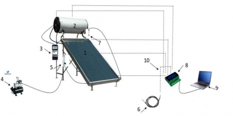
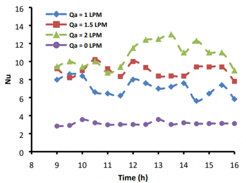
Khwayyir et al. [37] evaluated the thermal efficiency of a solar collector by introducing tiny air bubbles into the riser tubes at three variable fair low rates of Qa=1, 1.5, and 2 L/min with a comparison against no air injection (Qa=0 L/min). Figure 39 shows a schematic diagram of experimental apparatus. The flat plate solar collector was 1000x2000x80 mm in length, breadth, and thickness, of seven riser tubes and 8 mm of internal diameter and thickness of 0.6 mm. Also, a perforated silicon tube was employed for the air injection. Figure 40 elaborates the variation of Nu against operational time for different air flow rates. Based on the results of Figure 40, it is recommended to operate the air bubble injection at the highest flow rate to guarantee the highest solar collector's thermal performance.
Jawad et al. [38] studied what would happen if tiny bubbles of air were injected into a water stream moving through a copper tube wound in a double spiral configuration, with a length of 15 meters, a diameter of 0.012 meters, and 11 turns. A matte black paint containing a nanomaterial (thermal dye with 5% of TiN) was also used to coat the inside of the solar collector. In the beginning of the year, the finest testing circumstances in the province were found in Babylon, Iraq, at a longitude of (44.4) East and a latitude of (32.4) North, where the performance of the solar collector was tested experimentally. A venturi was used to introduce air into the tubes of the solar water collector, where it would subsequently flow with the water. The results reveal that the temperature differential between the inlet and exit, as well as the incoming and departing systems, grows as the mass flow rate decreases. When the water and air bubble flow rates were 1 L/min and 0.3 L/min, respectively, the greatest temperature differential in the closed system was 36.1℃. When the system was opened, a maximum temperature differential of 12.5 degrees Celsius was observed between the water and air bubble flow rates of 1 L/min and 0.3 L/min, respectively.
Table 3 summarises the relevant studies of utilising air bubble injection in solar collectors with showing the most important findings of these studies.
Figure 39. A schematic diagram of experimental apparatus [37]
Table 3. A summary of relative studies of air bubble injection in solar collector
|
References |
Configuration |
The Main Considered Parameters |
Study Type |
Highlighted Results |
|
Panthalookaran and George [35] |
A flat-plate solar collector with a cycle of humidifying and dehumidifying. |
The cooling of the solar collector is affected by the air-to-water ratio and the inner diameters of the absorber tubes. |
Experimental |
Solar collectors can be cooled more efficiently with two-phase flows, which also cool the absorber plates of solar collectors better. |
|
Shemelin and Matuska [36] |
The solar collector's riser tubes were injected with little air bubbles. |
Thermal performance, temperature, solar radiation, and efficiency. |
Experimental |
The higher air flow rate is the higher solar collector's thermal performance. |
|
Khwayyir et al. [37] |
Solar collectors for both air and water. |
The output of the solar collector. |
Experimental and analytical |
When compared to a standard solar system, it is conceivable to get up to 30% more energy from the sun. |
|
Jawad et al. [38] |
A solar collector uses a copper tube set up in a double spiral to channel a stream of water through tiny bubbles of pressurised air. |
The change caused by introducing tiny bubbles of air into water flowing through a double-helix copper tube. |
Experimental |
When the mass flow rate drops, a rise in the temperature difference between the inlet and exit happens in both the incoming and outgoing systems. The largest temperature difference in the closed system occurred when the water and air bubble flow rates were 1 L/min and 0.3 L/min, respectively. |
Figure 40. Change of Nu against operational time for different air flow rates [37]
The application of two-phase flow of air and water is identified in several implications such as the solar energy, oil and chemical industries, and biogas energy. Due to the high viscosity and density ratio, the way air bubbles move in a column of liquid can be thought of as very complicated. The following details the relative studies from the open literature that evaluate the application of air bubble injection in different medias.
Han et al. [39] investigated the migration of air bubbles migrate into a vibrated cement mortar (Figure 41). The air bubble movement was modeled using expandable polystyrene (EPS) beads with EPS dispersion. The density was calculated using the unit volume weight of three separated layers in a cylinder. The air content of fresh state concrete is a critical component in determining hardened concrete durability. Figure 42 shows that for non-vibration mode, there is insignificant relationship between the total area of air bubbles and the plastic viscosity. This is not the case for vibration mode where a significant reduction of plastic viscosity can be noticed after increasing the total area of air bubbles.
Figure 41. A schematic diagram of vibrated cement mortar with cylinder mold and formulating samples [39]
Figure 42. Influence of plastic viscosity on the total area of model air bubble for vibration and non-vibration modes [39]
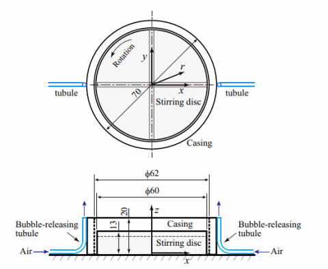
In a cylindrical tank, Uchiyama and Ishiguro [40] explored the connections between escalating air bubbles and the vortex core of whirling water flows. Figure 43 shows a schematic diagram of the stirring disc and bubble-releasing tubules. Tubules located close to the stirring disc release tiny air bubbles, and a revolving disc installed in the center of the tank's bottom creates swirling water flows around the tank's central (vertical) axis. Because of the buoyancy effect, the bubbles ascend helically in the spinning water flow, and some are entrained into the vortex core. The processional amplitude of the vortex core is boosted by the bubbles when the bubble flow rate Qg is extremely low. Figure 44 depicts this fact where any increase of Qg would introduce a decline in the processional amplitude of the vortex core.
Figure 43. A schematic diagram of stirring disc and bubble-releasing tubules [40]
Figure 44. Influence of bubble flow rate on processional amplitude of vortex core [40]
As illustrated in Figure 45, Ulaganathan et al. [41] investigated the local velocity profile of bubbles in -lactoglobulin (BLG) solutions for BLG adsorption at low bulk concentrations. The effect of pH and ionic strength on the dynamic surface characteristics of BLG at the solution/air interface has been assessed. Figure 46 demonstrates a reduction of the time required to produce an immobile stiff surface layer at the rising bubble surface as a result to increasing the pH between 3 to 7.
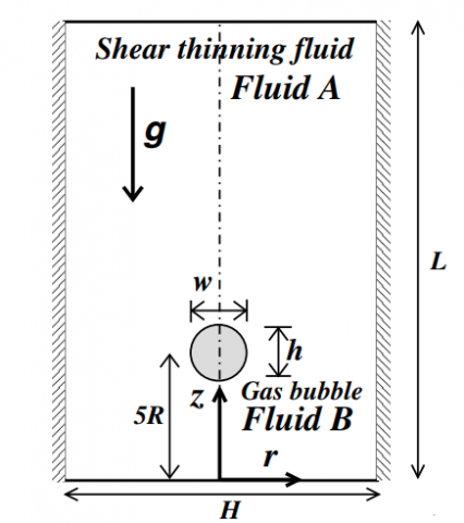
Premlata et al. [42] used a volume-of-fluid technique in the axisymmetric domain to investigate an air bubble rising in a non-Newtonian fluid (Figure 47). The governing equations are mass and momentum conservation paired with a Carreau-Yasuda model for the VR of the non-Newtonian fluid. The shear-thinning/thickening propensity of the surrounding fluid varied for various Gallilei and Eötvös numbers in a parametric research. The effects of these variables on the location of the center of gravity, the aspect ratio of the bubble, and the bubble form as they change over time were examined. It was revealed that increasing the shear thinning propensity enhances increased velocity and reduced bubble deflections.
Figure 45. Graphical representation of the case study [41]
Figure 46. Influence of pH of BLG solution prepared in 10 mM citric phosphate buffer on distance at which the bubble reaches terminal velocity (Ht). The symbols in graph represent as follows: (⌺) BLG5×10-7 M, (□) BLG1×10-6 M, (∆) BLG2×10-6 M [41]
Figure 47. A schematic diagram of an air bubble rising in a non-Newtonian fluid [42]
Cao et al. [43] tracked the interface of a rising air bubble in water with different thermos-physical properties that can be squeezed. They deployed a method that uses both the level set and amount of fluid. More specifically, Cao et al. [43] looked at how the difference in temperature between the air bubble and the water around it affected its zigzag movement. Figure 48 shows the shape changes and the structure of the wake that interpret the zigzag motion. During the zigzag motion, the hairpin vortex with 2R mode can be noticed to shed itself periodically.
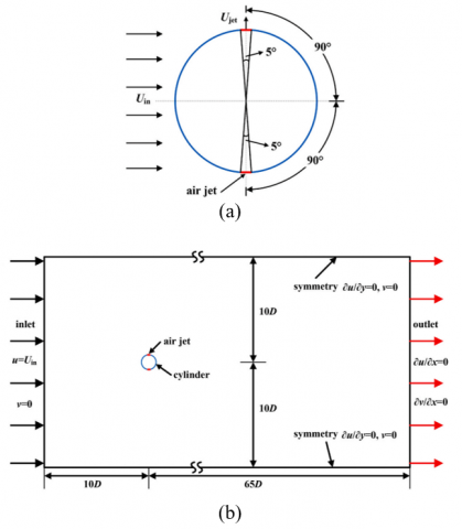
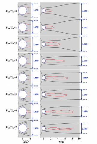
Zhu et al. [44] examined the impact of the injection velocity of two air jets positioned at the two shoulders of a circular cylinder on vortex shedding at a low Reynolds number (Re=100) (Figure 49). The air jets create a gas-liquid two-phase fluid in the wake by injecting air flow as well as momentum into the cylinder boundary layer. Air columns produced by jets roll up to produce air bubbles at Ujet/Uin, delaying the production of vortices to some extent (Figure 50). The time-mean drag coefficient and the variability of the lift coefficient can both be reduced by up to 99.93% and 17.07%, respectively, in a condition of sufficient momentum.
Figure 48. Evolution of (a) bubble volume, (b) vertical position, and (c) sphericity for 10mm bubble [43]
Figure 49. A schematic diagram of the circular cylinder with a pair of air jets placed at both sides: (a) geometrical dimensions of the circular cylinder equipped with a pair of air jets (b) computational domain and boundary conditions [44]
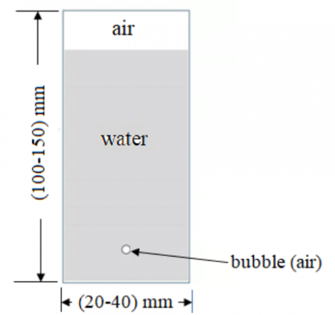
Hussein et al. [45] employed the dynamic meshing approach to analyse bubble rising through the water column using the user defined function code, as illustrated in Figure 51. The rising velocity of an air bubble through a stagnant water column has been explored. Also, the effects of the aspect ratio on the rising velocity column dimension, and bubble size have been studied. Figure 52 indicates an increase in the bubble rising velocity due to increasing the bubble size while the shape of the bubble changed from ellipsoidal to ellipsoidal cap shape. The column diameter has an effect on the rising velocity of air bubbles. In all instances, the air bubble was seen advancing toward the top of the water column with oscillation.
Figure 50. Comparison of contours [44]
Figure 51. A schematic diagram of possible flow regimes in bubble columns [45]
Sheng et al. [46] evaluated the influence of air bubbles on fine powder discharge behavior, including the pressure change within the silo and discharge mass flow rate. At the start of the discharge operation, the powder bed in the silo collapses, causing the pressure in the silo to quickly shift. Furthermore, the relationship between the size of the fine powder and the bubble size, bubble rising velocity, number of bubbles, and frequency of bubble creation is examined in depth. The bubble characteristics in the various particle size experimental scenarios are compatible with the Geldart particle categorization of the powders utilised. Figure 53 depicts the growth of average bubble rising velocity due to increasing the particle size.
Figure 52. Time growth of rising velocity at various bubble size [45]
Figure 53. Variation of average bubble rising velocity against the particle size [46]
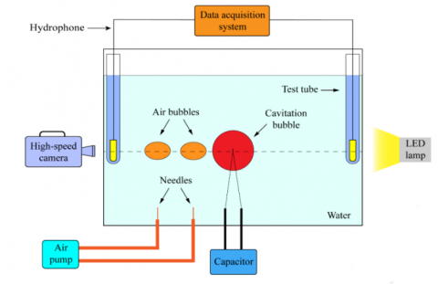
Li et al. [47] assessed the effect of the number of air bubbles on the strength of a cavitation bubble's collapse. This helps to understand the mechanism of air entrainment, which reduces cavitation erosion and improves the influences of aeration in hydraulic engineering. Figure 54 shows a schematic diagram of the system that introduces sparks to make a cavitation bubble. There are three ways to arrange air bubbles: two bubbles on the same side, one bubble on each side, and four bubbles all around. A hydrophone was used to figure out how loud the noise is when a cavitation bubble bursts. The findings of this study explored that the number of the air bubbles and cavitation bubble, relative distance, and size have considerable influences on the direction of the cavitation bubble's movement, the oscillation time, and the sound pressure before bubble’s collapsing. However, these findings are existed in the choice where the air bubbles can interrelate with the cavitation bubble.
Figure 54. A schematic diagram of the experimental gadget [47]
Figure 55. A schematic diagram of the experimental apparatus [48]
Figure 56. A schematic diagram of an experimental apparatus of submerged vacuum membrane distillation system [49]
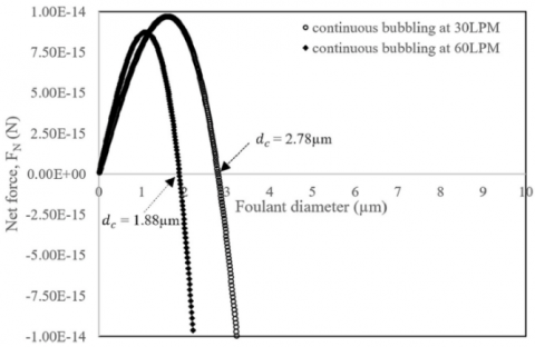
Figure 57. Influence of net force on the foulant diameter at two continuous air bubbling flow rates [49]
Figure 58. A schematic diagram of the experimental setup [50]
When a cavitation bubble explodes, Xu et al. [48] investigated how a single air bubble influences the amount of noise produced. This is a critical step in learning how to employ air entrainment in hydraulic engineering to prevent cavitation. As seen in Figure 55, a low-voltage electric discharge device under water creates a cavitation bubble that interacts with a rising air bubble. The experiments were carried out considering the center of the cavitation bubble, the center of the air bubble, and the hydrophone probe are roughly on the same horizontal line. The findings showed that the distance, size of an air bubble and roundness have a significant influence on the collapsing of bubble and associated sound.
As illustrated in Figure 56, Chang et al. [49] investigated the viability of aeration to mitigate the membrane scaling of a submerged vacuum membrane distillation system. The influence of aeration rate was examined for two scenarios of intermittent and continuous modes. Larger salt crystals including magnesium sulphate and sodium chloride were formed on the membrane surface in the absence of aeration. However, the rate of flux reduction owing to fouling was greatly reduced in the presence of air bubbling. The experiments indicated that a continuous air bubbling at 30 L/min has resulted in a substantial decrease in scalants on the membrane surface due to surface shear. Figure 57 indicates that the utilisation of air bubbling flow rate of 30 L/min has improved cleaning efficiency.
Cheng et al. [50] appraised the time-varying process of bubble fusion and migration in a bubble plume using two fluid models. The experimental apparatus is depicted in Figure 58. The dynamic actions of the bubble plume, and the parameters impacting the stability of the bubble plume are quantitatively defined (Figure 59). The findings asserted that the water body's turbidity lowers in front of and behind the bubble curtain, proving that the bubble curtain technology is useful in dredging engineering. The ventilation pressure and pipe construction influenced the quantity, size range, and median value of bubbles in the flume. According to the general linear model, the bubble plume's fusion height is the most susceptible to variations in bubble tube hole spacing, and the air flow at the bubble hole has the largest effect on the bubble plume's migratory properties.
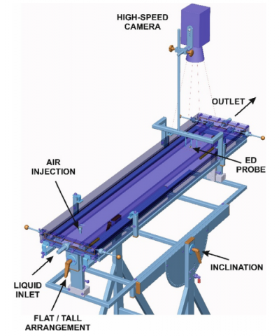
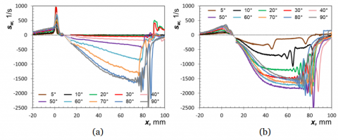
According to Ezeji and Tihon [51], individual operational factors have an impact on the bubble induced wall shear rate. A positive peak at the bubble front location is shown in Figure 60 along with a peculiar form of wall shear rate that was observed in the middle of a flat channel, which follows a negative plateau caused by reverse flow in the liquid layer around the bubble. The frontal morphologies of huge bubbles in flat channels are quite similar, as are the wall shear rate profiles caused by various sized bubbles. Widening the channel, on the other hand, has insignificant impact while contributing to a considerable growth in the bubble rise velocity. The rising bubbles are driven towards the roof wall when the channel is sloped which leads to two distinctive wall shear rate profiles at the channel's opposing walls, as represented in Figure 61.
Note: To characterize the interaction between horizontal flow velocity and time, four sampling points with a height of 1.5 m and 3 m on the centerline of the orifices were chosen and designated to as P1-4
Figure 59. Horizontal velocity of water against the operational time of the bubble plume [50]
Figure 60. A schematic diagram of the designed experimental channel [51]
Table 4. A summary of the relevant studies that discussed the incorporation of air bubble injection through different medias
|
References |
Configuration |
The Main Considered Parameters |
Study Type |
Highlighted Results |
|
Han et al. [39] |
Cement mortar. |
How air bubbles move from one place to another. |
Experimental |
The viscosity affects the quality of hardened state cementitious materials. |
|
Uchiyama and Ishiguro [40] |
A cylindrical tank to evaluate the connections between rising air bubbles and the vortex core of whirling water flows. |
The size of the movement of the core of the vortex. |
Numerical |
The bubbles have an impact on how the vortex funnel formed at the water's surface is shaped. |
|
Ulaganatha et al. [41] |
Rising of air bubbles in β-lactoglobulin solutions. |
Local velocity profile. |
Experimental |
BLG does not have the maximum surface active at the IEP under dynamic circumstances within the range of BLG concentrations evaluated by the rising bubble method. |
|
Premlata et al. [42] |
Rising of air bubble in a Newtonian fluid. |
The effect of the bubble's aspect ratio and how its shape changes over time. |
Numerical |
When the Gallilei number is high and the E¨otv¨os number is low, the bubble deforms more. |
|
Cao et al. [43] |
Rising of air bubble cavitation. |
The center of the cavitation bubble, the center of the air bubble, and the hydrophone probe. |
Experimental |
While the dimensionless distance (γ) and dimensionless radius roundness ratio (ε’) are crucial variables in defining the cavitation bubble's collapse direction, the direction of collapse is nearly identical to the collapse sound pressure. |
|
Zhu et al. [44] |
There are three different methods to organize air bubbles: two on the same side, one on each side, or four bubbles all around. |
The direction the bubbles move in depends on how far apart they are, how big they are, and how many there are. |
Experimental |
The air bubbles in aeration techniques should be tiny, frequent, and uniformly dispersed under the same aeration concentration. |
|
Hussein et al. [45] |
Rising of air bubble in water that can be squashed and has different thermos-physical properties. |
The zigzag movement of a bubble of air that can be squashed. |
Numerical |
The vorticity component oscillates at the same frequency as zigzag motion. |
|
Sheng et al. [46] |
A pair of air jets at the top and bottom of a cylindrical shape. |
A pair of air jets' injection velocity. |
Numerical |
The air bubble-vortex interference, as well as the merging and splitting of air bubbles, are all affected by the bubble size and the velocity distribution of the surrounding fluid. |
|
Li et al. [47] |
Rising of air bubble through the water column. |
The speed at which the bubble rises is affected by the size of the column, the size of the bubble, and the number of sides the bubble possesses. |
Numerical |
In all instances, the air bubble was seen advancing toward the top of the water column with oscillation. |
|
Xu et al. [48] |
Rising of air bubble in fine powder. |
The size of the fine powder is affected by the size of the bubbles, how quickly they rise, how many bubbles there are, and how often they form. |
Experimental |
The bubble dynamics and fine powder discharge behavior were illustrated. |
|
Chang et al. [49] |
Aeration maintains a clean membrane of a submerged vacuum membrane distillation. |
Influence of aeration rate for both intermittent and continuous modes. |
Experimental |
In the S-VMD system, air bubbling is a viable and effective strategy for reducing membrane scaling. |
|
Cheng et al. [50] |
In a bubble plume, bubbles come together and move around. |
The elements that influence the bubble plume's stability. |
Experimental |
According to a mechanical study of plume stability, Wn is the most important factor influencing bubble curtain collapse. |
|
Ezeji and Tihon [51] |
Wall shear rate caused by bubbles. |
Bubble characteristics. |
Experimental |
Even when the bubble rise velocity is significantly accelerated, widening the channel has little impact. |
|
Khalaf et al. [52] |
In a rectangular chamber, paraffin wax (PCM) is melted when air bubbles are placed there. |
The effect of air bubbles on the rate of dissolution and the temperature rise. |
Numerical |
Due to the existence of air bubbles at the solution's base and surface, the total dissolving time has been cut by 7%. |
Figure 61. Wall shear rate profiles made by a rising bubble at different inclinations of the channel H×W=5×80 mm2: (a) channel roof, and (b) channel bottom [51]
Khalaf et al. [52] detailed a numerical study that looked at how the positioning of air bubbles in a rectangular cavity affected the paraffin wax melting (PCM). Paraffin wax melting is what the PCM stands for. The enthalpy-porosity combination (the ANSYS/FLUENT 16 programmer) was employed to undertake a numerical examination of the study. Paraffin wax phase transition materials (RT58) were being employed in this experiment. Researchers looked at the impact of air bubbles on the dissolution process and heat transmission by analysing three different bubble positions (top, middle, and bottom) inside a rectangular cavity. In addition, scientists looked at how air bubbles affect the melting time of paraffin wax. The time required to finish the dissolving process is 7% faster when air bubbles are presented at the bottom and top of the solution as opposed to the centre. Air bubbles have been found to speed up the dissolving process on its own, and it has also been shown that the dissolving process will be sped up when it is known that the volume of PCMs is bigger since it includes the volume of air bubbles.
Table 4 summarises the relevant studies of utilising air bubble injection in in different medias with illustrating the most important findings.
Based on the reviewed studies in sections (2-5), there are opportunities and difficulties that should be carefully considered when using air bubble injection to improve heat transfer in industrial sectors. An analysis of these perspectives is provided in the following section.
Heat transfer rates can be considerably increased by injecting air bubbles, which encourage fluid mixing and disturb boundary layers besides attaining efficient energy systems. Specifically, the temperature difference between the heat transfer fluid and the surface is decreased as a result of improved heat transfer efficiency, which also reduces energy usage and operating expenses. As a result, overall heat exchange efficiency is increased.
The propensity of fouling can be lowered using injected air bubbles. This technology has a positive influence on removing particles or deposits from heat exchange surfaces. This function is particularly useful in other sectors that are prone to fouling, such as water desalination systems and specifically membrane technology.
Referring to solar collector systems, air bubble injection can improve heat transfer fluid contact with the absorber surface via increasing turbulence and fluid mixing inside the collector. The efficiency of the collector as a whole and heat absorption can be therefore improved. Air bubble injection can also make up for decreased natural convection in conditions of lower solar radiation, such as cloudy days or the early morning and late afternoon hours, and maintain collector efficiency. Moreover, effective air bubble injection can ensure the temperature distribution across the absorber of collector and therefore can reduce the risk overheating. Detaching particles from the absorber surface can reduce the accumulation of deposits and prevent fouling.
On the other hand, it should be noted that heat transfer through air bubble injection has a number of challenges. These include the bubble coalescence and breakup. Indeed, bubbles can condense or disperse during flow. This would cause a change in their size and distribution. Thus, controlling bubble properties is crucial to preserving steady improvement in heat transfer. Also, the pressure loss across heat exchangers or other equipment increases when air bubbles are introduced. Thus, it is vital to strike a balance between improved heat transfer and allowable pressure drop levels. Some other challenges can be raised through scaling-up air bubble injection systems. Maintaining uniform bubble dispersion and improving effective heat transfer present obstacles when translating lab-scale results to industrial-scale applications. Moreover, designs for solar collectors get more sophisticated when bubble injection technologies are integrated. System dependability and maintenance needs may be impacted by the inclusion of bubble production mechanisms, controllers, and other components.
Based on the above argument, interdisciplinary research is required to efficiently use air bubble injection for heat transfer augmentation. This calls for the use of control engineering, materials science, heat transfer, and fluid dynamics. The development of sophisticated bubble generating techniques, improvement of bubble size and distribution, and smooth integration of bubble injection into current operations should be the main goals. Additionally, bubble injection might work better when combined with other methods for improving heat transfer, including surface coatings or additives.
Air bubble injection's utility in a range of applications is now widely recognised. Heat exchangers, water desalination systems, solar collectors, and flow in various mediums are all examples of where this technology is applied. The air bubble method will be improved due to the extensive use of heat exchangers, the continued requirement for water purification, and the frequent usage of two-phase flow. It is also worth noting that the advantages of air bubble injection will be increasingly commonly used in other applications, especially in terms of energy savings, system efficiency, and productivity. Many unresolved and notable cases, such as those listed below, may be included in the future research:
Thermal systems have lately emerged as one of the most important systems in a number of technical applications, such as refrigeration, automobile, and solar water heaters. As a result, many efforts have been made to increase heat transmission in heat exchangers in order to obtain a variety of economic and environmental benefits, such as smaller sizes, lower costs, and lower energy usage. This paper surveyed the present state of air injection in a variety of applications. The impact of operational parameters on the development and setup of air injection applications is investigated. The most important findings of this review is that the efficiency in heat transmission is essential to enhancing performance, lowering energy use, and ensuring operational dependability in almost every sector of industry. The use of improved materials, heat exchanger design optimization, and the use of phase change materials are examples of advances in heat transfer enhancement techniques that have the potential to convert numerous sectors toward more resource- and sustainably-conscious methods. Some other important findings of this review are listed below as follows:
[1] Khan, M.Z.H., Mostafa, M.G. (2011). Aerobic treatment of pharmaceutical wastewater in a biological reactor. International Journal of Environmental Sciences, 1(7): 1797-1805.
[2] Zupanc, M., Kosjek, T., Petkovšek, M., Dular, M., Kompare, B., Širok, B., Blažeka, Ž., Heath, E. (2013). Removal of pharmaceuticals from wastewater by biological processes, hydrodynamic cavitation and UV treatment. Ultrasonics Sonochemistry, 20(4): 1104-1112. https://doi.org/10.1016/j.ultsonch.2012.12.003
[3] Fadavi, A., Chisti, Y. (2005). Gas–liquid mass transfer in a novel forced circulation loop reactor. Chemical Engineering Journal, 112(1-3): 73-80. https://doi.org/10.1016/j.cej.2005.06.009
[4] Kelessidis, V.C., Karydakis, G.I., Andritsos, N. (2007). Method for selecting casing diameters in wells producing low-enthalpy geothermal waters containing dissolved carbon dioxide. Geothermics, 36(3): 243-264. https://doi.org/10.1016/j.geothermics.2007.01.003
[5] Salimpour, M.R. (2008). Heat transfer characteristics of a temperature-dependent-property fluid in shell and coiled tube heat exchangers. International Communications in Heat and Mass Transfer, 35(9): 1190-1195. https://doi.org/10.1016/j.icheatmasstransfer.2008.07.002
[6] Dizaji, S. (2014). Heat transfer enhancement due to air bubble injection into a horizontal double pipe heat exchanger. Automotive Science and Engineering, 4(4): 902-910.
[7] Fsadni, A.M., Whitty, J.P. (2016). A review on the two-phase pressure drop characteristics in helically coiled tubes. Applied Thermal Engineering, 103: 616-638. https://doi.org/10.1016/j.applthermaleng.2016.04.125
[8] Sun, B., Yang, C., Wang, Z., Wang, X., Wang, N. (2019). Methodology for pressure drop of bubbly flow based on energy dissipation. Journal of Petroleum Science and Engineering, 177: 432-441. https://doi.org/10.1016/j.petrol.2019.02.021
[9] Yu, S., Yan, X., Zhou, L., Xu, A., Zhang, J., Gong, S. Zan, Y. (2020). Experimental study of bubbly-slug flow transition criteria in an vertical circular tube by using WMS. Frontiers in Energy Research, 8: 51. https://doi.org/10.3389/fenrg.2020.00051
[10] Obed, A.A., Abid, A.J. (2021). Performance study of the direct-coupled photovoltaic water pumping system for the rural-isolated agricultural region in Iraq. Journal of Techniques, 3(1): 37-46. https://doi.org/10.51173/jt.v3i1.273
[11] Bourouni, K., Chaibi, M.T., Tadrist, L. (2001). Water desalination by humidification and dehumidification of air: State of the art. Desalination, 137(1-3): 167-176. https://doi.org/10.1016/S0011-9164(01)00215-6
[12] Singh, G., Nandan, A. (2016). Experimental study of heat transfer rate in a shell and tube heat exchanger with air bubble injection. International Journal of Engineering, 29(8): 1160-1166. http://doi.org/10.5829/idosi.ije.2016.29.08b.00
[13] Bonafoni, G., Capata, R. (2015). Proposed design procedure of a helical coil heat exchanger for an orc energy recovery system for vehicular application. mechanics. Materials Science & Engineering Journal, 2412-5954.
[14] Li, H., Wang, Y., Han, Y., Li, W., Yang, L., Guo, J., Liu, Y., Zhang, J., Zhang, M., Jiang, F. (2021). A comprehensive review of heat transfer enhancement and flow characteristics in the concentric pipe heat exchanger. Powder Technology, 397: 117037. https://doi.org/10.1016/j.powtec.2021.117037
[15] Mohiuddin, S.A., Kaviti, A.K., Rao, T.S., Sikarwar, V.S. (2022). Historic review and recent progress in internal design modification in solar stills. Environmental Science and Pollution Research, 29: 38825-38878. https://doi.org/10.1007/s11356-022-19527-x
[16] Ahmed, S.F., Khalid, M., Vaka, M., Walvekar, R., Numan, A., Rasheed, A.K., Mubarak, N.M. (2021). Recent progress in solar water heaters and solar collectors: A comprehensive review. Thermal Science and Engineering Progress, 25: 100981. https://doi.org/10.1016/j.tsep.2021.100981
[17] Dizaji, H.S., Jafarmadar, S., Abbasalizadeh, M., Khorasani, S. (2015). Experiments on air bubbles injection into a vertical shell and coiled tube heat exchanger; exergy and NTU analysis. Energy Conversion and Management, 103: 973-980. https://doi.org/10.1016/j.enconman.2015.07.044
[18] Khorasani, S., Dadvand, A. (2017). Effect of air bubble injection on the performance of a horizontal helical shell and coiled tube heat exchanger: An experimental study. Applied Thermal Engineering, 111: 676-683. https://doi.org/10.1016/j.applthermaleng.2016.09.101
[19] Heyhat, M.M., Abdi, A., Jafarzad, A. (2018). Performance evaluation and exergy analysis of a double pipe heat exchanger under air bubble injection. Applied Thermal Engineering, 143: 582-593. https://doi.org/10.1016/j.applthermaleng.2018.07.129
[20] El-Said, E.M., Abou Alsood, M.M. (2018). Experimental investigation of air injection effect on the performance of horizontal shell and multi-tube heat exchanger with baffles. Applied Thermal Engineering, 134: 238-247. https://doi.org/10.1016/j.applthermaleng.2018.02.001
[21] Khorasani, S., Moosavi, A., Dadvand, A., Hashemian, M. (2019). A comprehensive second law analysis of coil side air injection in the shell and coiled tube heat exchanger: An experimental study. Applied Thermal Engineering, 150: 80-87. https://doi.org/10.1016/j.applthermaleng.2018.12.163
[22] Li, X., Sun, J., Xu, C., Li, Y., Zhang, R., Qian, L., Chen, Y. (2019). Visualization of bubble flow in the channel of a dimple-type embossing plate heat exchanger under different fluid inlet/outlet ports. International Journal of Heat and Mass Transfer, 145: 118750. https://doi.org/10.1016/j.ijheatmasstransfer.2019.118750
[23] Akhmadullin, I., Kartushinsky, A. (2021). CFD simulation of bubbly flow in a long coaxial heat exchanger. Thermal Science and Engineering Progress, 25: 100991. https://doi.org/10.1016/j.tsep.2021.100991
[24] Sinaga, N., Nisar, K.S., Kaood, A. (2021). Second law efficiency analysis of air injection into inner tube of double tube heat exchanger. Alexandria Engineering Journal, 60(1): 1465-1476. https://doi.org/10.1016/j.aej.2020.10.064
[25] Ghashim, S.L., Flayh, A.M. (2021). Experimental investigation of heat transfer enhancement in heat exchanger due to air bubbles injection. Journal of King Saud University-Engineering Sciences, 33(7): 517-524. https://doi.org/10.1016/j.jksues.2020.06.006
[26] Rashid, F.L., Talib, S.M., Hussein, A.K. (2022). An experimental investigation of double pipe heat exchanger performance and exergy analysis using air bubble injection technique. Jordan Journal of Mechanical and Industrial Engineering, 16(2): 195-204.
[27] Al-hotmani, O.M.A., Al-Obaidi, M.A., John, Y.M., Patel, R., Mujtaba, I.M. (2022). Optimisation of hybrid MED-TVC and double reverse osmosis processes for producing different grades of water in a smart city. Desalination, 534: 115776. https://doi.org/10.1016/j.desal.2022.115776
[28] Khalil, A., El-Agouz, S.A., El-Samadony, Y.A.F., Abdo, A. (2015). Solar water desalination using an air bubble column humidifier. Desalination, 372: 7-16. https://doi.org/10.1016/j.desal.2015.06.010
[29] Behnam, P., Shafii, M.B. (2016). Examination of a solar desalination system equipped with an air bubble column humidifier, evacuated tube collectors and thermosyphon heat pipes. Desalination, 397: 30-37. https://doi.org/10.1016/j.desal.2016.06.016
[30] Kabeel, A.E., Abdelgaied, M., Mahgoub, M. (2016). The performance of a modified solar still using hot air injection and PCM. Desalination, 379: 102-107. https://doi.org/10.1016/j.desal.2015.11.007
[31] Halima, H.B., Frikha, N., Gabsi, S. (2017). Experimental study of a bubble basin intended for water desalination system. Desalination, 406: 10-15. https://doi.org/10.1016/j.desal.2016.08.003
[32] Arunkumar, T., Kabeel, A.E., Raj, K., Denkenberger, D., Sathyamurthy, R., Ragupathy, P., Velraj, R. (2018). Productivity enhancement of solar still by using porous absorber with bubble-wrap insulation. Journal of Cleaner Production, 195: 1149-1161. https://doi.org/10.1016/j.jclepro.2018.05.199
[33] Fallahzadeh, R., Aref, L., Avargani, V.M., Gholamiarjenaki, N. (2020). An experimental investigation on the performance of a new portable active bubble basin solar still. Applied Thermal Engineering, 181: 115918. https://doi.org/10.1016/j.applthermaleng.2020.115918
[34] Rashid, F.L., Hussein, E.Q., Hussein, A.K., Younis, O. (2023). Parametric study of single air bubble rising through different salinity water column using volume of fluid (VOF) technique. Journal of Engineering Science and Technology, 18(1): 671-684.
[35] Panthalookaran, V., George, J.P. (2016). Experimental study on cooling of solar collectors using air-water mixture. Energy Procedia, 91: 303-311. https://doi.org/10.1016/j.egypro.2016.06.222
[36] Shemelin, V., Matuska, T. (2019). Performance modelling of dual air/water collector in solar water and space heating application. International Journal of Photoenergy, 2019: 8560193. https://doi.org/10.1155/2019/8560193
[37] Khwayyir, H.S., Baqir, A.S., Mohammed, H.Q. (2020). Effect of air bubble injection on the thermal performance of a flat plate solar collector. Thermal Science and Engineering Progress, 17: 100476. https://doi.org/10.1016/j.tsep.2019.100476
[38] Jawad, S.A., Abdul Redha, Z.A., Rashid, F.L. (2023). Thermal performance of flat plate solar water collector using air bubble injection. AIP Conference Proceedings, 2651: 050019. https://doi.org/10.1063/5.0133663
[39] Han, D., Lee, G.C., Yoon, S.J., Kim, K.M. (2015). Viscosity influence on rising behavior of model air bubbles in fresh mortar. Construction and Building Materials, 76: 10-15. https://doi.org/10.1016/j.conbuildmat.2014.11.016
[40] Uchiyama, T., Ishiguro, Y. (2016). Study of the interactions between rising air bubbles and vortex core of swirling water flow around vertical axis. Chemical Engineering Science, 142: 137-143. https://doi.org/10.1016/j.ces.2015.11.042
[41] Ulaganathan, V., Gochev, G., Gehin-Delval, C., Leser, M.E., Gunes, D.Z., Miller, R. (2016). Effect of pH and electrolyte concentration on rising air bubbles in β-lactoglobulin solutions. Colloids and Surfaces A: Physicochemical and Engineering Aspects, 505: 165-170. https://doi.org/10.1016/j.colsurfa.2016.03.059
[42] Premlata, A.R., Tripathi, M.K., Karri, B., Sahu, K.C. (2017). Dynamics of an air bubble rising in a non-Newtonian liquid in the axisymmetric regime. Journal of non-Newtonian Fluid Mechanics, 239: 53-61. https://doi.org/10.1016/j.jnnfm.2016.12.003
[43] Cao, Y., Canals, I.M., Macián-Juan, R. (2020). Path instability of a compressible air bubble rising in quiescent water with consideration of variable thermophysical properties. International Journal of Multiphase Flow, 129: 103320. https://doi.org/10.1016/j.ijmultiphaseflow.2020.103320
[44] Zhu, H., Tang, T., Wang, J. (2020). Modification of wake flow and air-bubble-vortex interference in the flow control of a circular cylinder with a pair of air jets: Effect of injection velocity. Ocean Engineering, 214: 107766. https://doi.org/10.1016/j.oceaneng.2020.107766
[45] Hussein, E.Q., Rashid, F.L., Hussein, A.K., Younis, O. (2021). Hydrodynamics of single bubble rising through water column using volume of fluid (VOF) method. Journal of Thermal Engineering, 7(Supp 14): 2107-2114. https://doi.org/10.18186/thermal.1051642
[46] Sheng, L.T., Hsiau, S.S., Wen, C.Y. (2021). Experimental investigation on air bubble dynamics during fine powder discharge in a silo. Advanced Powder Technology, 32(1): 106-120. https://doi.org/10.1016/j.apt.2020.11.021
[47] Li, J.B., Xu, W.L., Zhai, Y.W., Luo, J., Wu, H., Deng, J. (2021). Influence of multiple air bubbles on the collapse strength of a cavitation bubble. Experimental Thermal and Fluid Science, 123: 110328. https://doi.org/10.1016/j.expthermflusci.2020.110328
[48] Xu, W.L., Li, J.B., Luo, J., Zhai, Y.W. (2021). Effect of a single air bubble on the collapse direction and collapse noise of a cavitation bubble. Experimental Thermal and Fluid Science, 120: 110218. https://doi.org/10.1016/j.expthermflusci.2020.110218
[49] Chang, Y.S., Ooi, B.S., Ahmad, A.L., Leo, C.P., Leow, H.T.L., Abdullah, M.Z., Abd Aziz, N. (2021). Correlating scalants characteristic and air bubbling rate in submerged vacuum membrane distillation: A fouling control strategy. Journal of Membrane Science, 621: 118991. https://doi.org/10.1016/j.memsci.2020.118991
[50] Cheng, Y., Zhao, N., Zhang, K., Wei, W. (2021). Research on the plume stability of air bubble curtains under low transverse flow velocity environment in dredging engineering. Ocean Engineering, 232: 109133. https://doi.org/10.1016/j.oceaneng.2021.109133
[51] Ezeji, K., Tihon, J. (2022). Near-wall flow response to large air bubbles rising in inclined water channels. Chemical Engineering Science, 247: p.116914. https://doi.org/10.1016/j.ces.2021.116914
[52] Khalaf, A.F., Rashid, F.L., Basem, A., Abbas, M.H. (2023). Numerical study of the effect of air bubble location on the PCM melting process in a rectangular cavity. Mathematical Modelling of Engineering Problems, 10(1): 71-83. https://doi.org/10.18280/mmep.100109
[53] Al-Obaidi, M.A., Rasn, K.H., Aladwani, S.H., Kadhom, M., Mujtaba, I.M. (2022). Flexible design and operation of multi-stage reverse osmosis desalination process for producing different grades of water with maintenance and cleaning opportunity. Chemical Engineering Research and Design, 182: 525-543. https://doi.org/10.1016/j.cherd.2022.04.028
[54] Imasaka, T., Kanekuni, N., So, H., Yoshino, S. (1989). Cross-flow filtration of methane fermentation broth by ceramic membranes. Journal of Fermentation and Bioengineering, 68(3): 200-206. https://doi.org/10.1016/0922-338X(89)90137-2