Rana A. Al-Luhaibi*![]() | Ibrahim Thamer Nazzal
| Ibrahim Thamer Nazzal![]()
© 2023 IIETA. This article is published by IIETA and is licensed under the CC BY 4.0 license (http://creativecommons.org/licenses/by/4.0/).
OPEN ACCESS
As the electronics industry gravitates towards smaller yet more powerful devices, the need to enhance traditional heat sink cooling capabilities without enlarging their footprint has become increasingly urgent. This necessity stems from the adverse effects of high temperatures on electronic performance and the limitations of traditional heat sinks' thermal transfer. This study addresses the challenge by investigating modifications to heat sink design, specifically through the strategic perforation of fins to increase their surface area, thereby improving heat dissipation without augmenting size. A series of lateral plate fins, perforated for increased surface area, were positioned on the base of a heat sink. The thermal performance of these modified heat sinks was then tested experimentally within a long, square cross-sectioned channel, facilitating forced air passage at manually controlled speeds. Three heat sink samples were compared under variable airflow rates to ascertain the cooling efficiency of the perforated fins. Three distinct rectangular heat sinks were utilized. The first featured holes of varying diameters arranged horizontally (PHS-HV), while the second had vertically varying diameters, with smaller ones at the top and larger ones at the bottom (PHS-VV). These perforated heat sinks were contrasted against a non-perforated heat sink under different thermal loads and Reynolds numbers. Results demonstrated enhanced heat dissipation, Nusselt number, and heat transfer coefficient in perforated fins compared to non-perforated ones. Notably, the use of different hole diameters in the same fin positively impacted heat dissipation, with horizontal diameter expansion (PHS-HV) outperforming vertical expansion (PHS-VV). The heat transfer improvement was 8.53% for PHS-HV and 4.36% for PHS-VV at Re 20000. Furthermore, perforation contributed to a decrease in heat sink mass compared to solid heat sinks, indicating cost and material savings. This study underscores the potential of strategic perforation in augmenting heat sink performance for next-generation electronics.
heat sink, forced convection, perforated fin, perforation arrangement
In the rapidly advancing landscape of electronic devices, an escalating generation of heat has become a significant challenge. This phenomenon necessitates improved heat dissipation strategies for these devices, with plate fin heat sinks emerging as a common solution due to their manufacturing simplicity. Over numerous decades, the performance of rectangular plate fins has been rigorously examined, catalyzing various innovative approaches for enhancing the heat transfer capabilities of heat sinks. Modifications in fin geometry as a means to improve heat sink performance have been explored in a multitude of studies [1]. This has paved the way for more advanced strategies, such as the integration of vortex generation into fins [2] and the incorporation of ribs within the heat sink passage [3, 4]. The concept of perforated fins has also been investigated extensively. For instance, Sara et al. [5] conducted an experimental study on heat transfer through a perforated flat plate, concluding that the dissipated heat increased with the use of a perforated plate in comparison to a solid one. In a numerical analysis, Shaeri et al. [6] examined the fluid flow and convective heat transfer from rectangular perforated fins with square holes positioned on the lateral surface of the fins. Their study demonstrated that the novel perforated fins not only exhibited superior overall heat transfer but also significantly reduced weight compared to solid fins. Venkitaraj and Sanooj [7] further extended the investigation to various types of perforations. Their numerical analysis estimated the improvement in convection heat transfer of an array of fins with circular, elliptical, square, and triangular perforations, studying both their performance and material mass. Their results indicated that the fin array with circular perforations exhibited the highest performance relative to other designs considered in their study.
The exploration of innovative ways to enhance heat transfer in fin heat sinks has been a subject of intense study, with the use of various perforations showing significant promise. A study by Sonawane and Palande [8] revealed that perforated pin-fin heat sinks outperformed their solid counterparts in terms of heat transmission rates. In further support of these findings, Shaeri and Bonner [9], Wang et al. [3] conducted an experimental investigation comparing the hydraulic and thermal performance of laterally perforated-finned heat sinks. Their study utilized three evenly spaced square cross-sectional perforations of varying sizes along the length of the heat sinks. The results indicated that heat dissipation was significantly improved in the perforated fin compared to the unperforated fin. Expanding on this concept, Chingulpitak et al. [10] examined the thermal performance of laterally perforated plate-fin heat sinks featuring various numbers and diameters of circular perforations. Their analysis suggested that the thermal performance factor-which incorporates both the Nusselt number and friction factor-could be effectively used to determine appropriate design parameters. Their perforated heat sink design demonstrated a remarkable 10.6% improvement in thermal performance and a 28% reduction in heat sink mass compared to the solid alternative. Huang and Huang [11] also evaluated the performance of a pin-fin heat sink employing perforations and splitters, observing that these features considerably enhanced its thermal performance.
Despite the wealth of research into perforated fin impacts on heat sink performance, a gap remains in the literature. To the best of the authors' knowledge, no prior study has examined the implications of varying hole diameters within the same fin on a heat sink. Therefore, the present study aims to fill this void by experimentally studying the thermal performance of a perforated fin heat sink, featuring distinct hole diameters in the same fin, and comparing it to a solid fin. This investigation will utilize an in-line rectangular fin heat sink, with selected hole diameters of 3, 3.5, 4, and 4.5 mm. Two patterns of perforation will be compared to a non-perforated fin heat sink, with the primary objective being to analyze the thermal performance of a lateral perforated plate-fin heat sink for electronic cooling devices using different perforations. This endeavor will contribute to the ongoing optimization of heat sink design for improved thermal performance.
2.1 Apparatus description
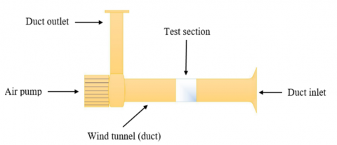
To achieve the main of this work, a forced convection-horizontal- device is used as shown in Figure 1.
The experimental setup is schematically illustrated in Figure 2. It consists of a wind tunnel, heating system, heat sinks, air pump, and measurement devices to measure the temperature, and flow velocity. The wind tunnel system has an air pump, a test section, and a flow straightener.
(1-Air pump. 2-Fan. 3-Throttle opening. 4-Test section. 5-Electrical heater. 6-Total head tube. 7-Test section. 8-Thermometer. 9-Air inlet. 10-Digital thermometer. 11-Control panel. 12-Inclined manometer. 13-Watch timer).
Figure 1. Forced convection device-horizontal duct
The air flows steadily across the heat sink which dissipates the heat continuously. The inlet of the duct is designed as a curvy shape (bell mouth) to facilitate air entering the duct smoothly without separate layers of air. The air pump has a maximum flow rate of 0.49 m3/s which is placed at the end of the wind tunnel to suck the required air through the test section from the surrounding of the device and takes it out by vertical pipe end with a throttle opening (125) mm the diameter of the pipe. Moreover, at the exit of the wind tunnel, there is a movable gate to close and open the pipe and adjust the flow of air passing through the tunnel. The duct at the area after the test section contains a flow straightener (honeycomb) to make the airflow in a laminar stream. Flow straightener has a horizontal square duct (125×125) mm, (1300) mm in length, constructed of iron (1) mm thickness.
Figure 2. Schematic diagram of forced convection device
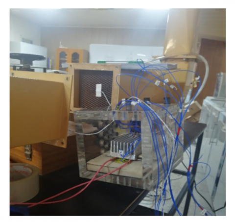
The test section was mounted in the middle of the wind tunnel and made of very thick acrylic (19.5 mm). The top and bottom walls of the test section have a cut-out region where holes are installed to enable the entry of thermocouples to measure temperature distribution on the heat sinks and cooling rate. All the samples of the heat sink were placed inside the test section. as cleared in Figure 3.
Figure 3. Heat sink inside the test section of the wind tunnel
2.2 Samples description
The heat sinks are made of aluminum alloy (1006) which has a thermal conductivity of (237) W/m. K. The width (Ly) the length (Lx), and the thickness (t) of the heat sink base are 12, 100, and 55 mm, respectively. This study includes three heat sink models, as presented in Table 1.
Table 1. Types of heat sink
|
Heat Sink Type |
Perforation Number |
Surface Area (mm2) |
Weight (gr.) |
|
Solid |
Non |
51420 |
339.7 |
|
PHS-HV |
12 |
51621 |
315.8 |
|
PHS-VV |
12 |
51589 |
316 |
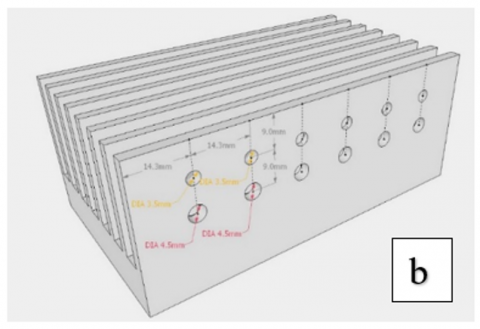
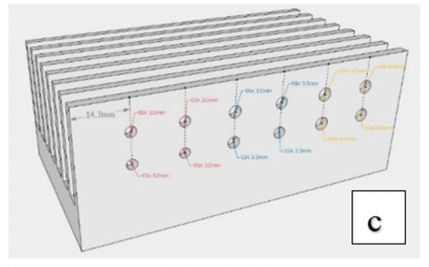
The holes in the fins (perforation pattern) are varied as shown in Figure 4.
Figure 4. Types of heat sinks: (a) non-perforated; (b) PHS-VV; (c) PHS-HV
2.3 Preparation for the experiment
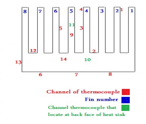
To supply a constant heat flux surface for heat sinks, an electrical heater (AC) was selected. Variac (AC) is used to adjust the power supplied to the heater with a specified voltage. All the heating body is covered by insulated (by using Teflon) from the sides, except on the top, where it was in contact with a heat sink. K-type thermocouples are utilized to measure the temperature of the heat sink and cooling air. Anbai AT4516 data logger with a sixteen-channel selector to connect the set of thermocouples. All the thermocouples were calibrated. In this study, fourteen channel used, three thermocouples were embedded in the heat sink for measuring the base of the heat sink, and eleven thermocouples were attached to the surface of the heat sink as illustrated in Figure 5.
Figure 5. Thermocouples locations on the heat sink
The velocity of the airflow that enters the test section of the wind tunnel is measured using an anemometer (BENETECH, 0-30 m/s). The performance of the heat sink was studied using non-perforated and two perforated heat sinks. The non-perforated heat sink, whose fins are solid rectangles without holes as can be seen in subgraph (a) of Figure 4, weight is (339.7) gr. Others are transversely perforated for making a comparison between them in absorbing and removing heat away from objects to be cooled Figure 4(b) and 4(c). Also, all samples have the same dimensions, as mentioned in Table 2, they are constructed of a flat plate with extruded rectangular 8 fins (2.5) mm the thickness, the space or channels between fins (3500) mm2, they are seven-channels with width (5) mm. These holes are made to test the thermal performance of the heat sink in terms of dissipation heat and cooling rate and compared their behavior with other samples.
Table 2. The dimensions of the heat sink
|
Dimensions |
Value (mm) |
|
Heat sink width (W) |
55 |
|
Heat sink length |
100 |
|
Heat sink base thickness |
12 |
|
Fin height |
28 |
|
Fin thickness |
2.5 |
|
Fin number |
8 |
|
The thickness of the interface material |
1 |
2.4 Experimental procedures
After setting the forced convection device, all the parts are connected to implement the experiment. Then, it is operated the device and changing setting required air velocity using the gate that is put at the outlet pipe, the range of air velocities used in this study (1.5, 2, 2.5, 3. 3.5, 4) m/s. Moreover, it is adjusted the required voltage (20, 40, 60, 80, and 100) V, and waiting for a period of time (about12 mins) until the system is stable thermally. Afterward, it is reading all the temperature at different points on the heat sink and the area before and after the test section. After taking readings for the first heat sink, replace it with a second one for testing, then the third one. All readings were used in theoretical calculations, to obtain the results for studying, analyzing, and conducting the comparison of heat sink types in terms of heat dissipating rate and overall thermal performance.
3.1 Heat transfer rate
Transferring heat from hot surfaces to surrounding fluid is being according to Newton’s law for cooling. It state “the rate at which an object cools is directly proportional to the difference in temperature between the object and object’s surroundings”, and also is directly proportional to the contact area between them. The rate of convective heat, transferred from the heat sink surface to the surrounded air can be determined from the following equation:
Q ̇conv.=Q ̇elect. ̶Q ̇loss (1)
where, Q ̇conv. is steady-state convection heat. The electrical heat input can be computed from the voltage and current supplied to the heater: P=IV, where I and V are current and voltage respectively. In Eq. (1) the Q ̇loss is equal to the summation of conduction and radiation heat losses, and both are neglected as low effects. The convection heat transfer obtained from the test section can be expressed as:
Q ̇conv.=m ̇CpΔT (2)
m ̇ is the mass flow rate of air and Cp is the specific heat of air. Two parameters are used in this study, electrical voltage and air velocity. The mass of air flowing through the duct contacted the heat sink, passed around fins and through the fin spaces, have been obtained by applying the following equation:
m ̇=ρVA (3)
where, ꝭ and V are the density and velocity of air respectively, A is the area of fluid that touches the heat sink, where the heat is exchanged from the high-temperature body (heat sink) to low-temperature surrounded fluid (air).
A=air layer beside the heat sink+air layer above the heat sink+air layer between fins(spaces), The thickness of the air layer taken in this study is (6 mm), as cleared in Figure 6.
Figure 6. Air layer surrounded heat sink (red area)
then getting Q ̇conv. value by:
Q ̇conv.=hAsΔT (4)
ΔT is the difference of temperatures, ΔT=Ts-Tm, where Ts is the temperature of the heat sink surface and Tm is the mean temperature, the Eq. (4) become:
Q ̇conv.=havAs(Ts-Tm) (5)
hav, As are the average heat transfer coefficient and total surface area of the heat sink respectively. The surface area As of the whole heat sink -that is exposed to forced air- includes two parts (the upper and lower part of the heat sink). The upper part is also divided into two parts, as follows:
Asf: fins surface areas, i,e., equal to the sum of fin surface areas.
Ass: surface area of fin spaces.
The total surface area of fins (Asf)=fin surface area (Af) [12].
X fins number (Nf) (6)
Solid fin surface area=Wf Lf+2Wf Hf+2Hf Lf.
Perforated fin surface area (Af)=top+front and back+{[2 X (fin side-total holes areas)]+(internal annual area X holes number)}.
Or, as cleared in Figure 7:
Af = [Wf Lf + 2Wf Hf + Ap] (7)
Ap is the area of a side face of the perforated fin, it could be conducted from the
Ap=2(HfLf-Ah)+Pi
Pi and Ah, are the inner perforation surface and hole area respectively, Pi has a rectangular shape its area is perforation perimeter Pp multiplied by Wf. Now, Eq. (7) become:
Af=Wf X Lf+2 X (Wf X Hf)+{[2 X (Hf X Lf)-((π/4 Dp2) X Np)]+[π Dp X Wf X Np]}
Spaces area Ass=area of fin space multiplied by space number, as follows:
Ass=(LfS)Ns (8)
S and Ns are fin space and space number respectively. As required physical values should be taken from thermal tables at the mean (bulk) air temperature Tm, the mean temperature might be determined by the equation:
Tm=(Tout+Tin)/2 (9)
Tout is outlet air temperature (after the test zone) and Tin is inlet air temperature (before the test zone), both were measured by thermocouples, substitute that in Eq. (5):
Q ̇conv.=hav.AS[TS ̶((Tout+Tin)/2)] (10)
As the heat convection happened from the whole heat sink, and the surface area of the heat sink includes base and fin area, Eq. (10) could be written as:
Q ̇conv.=hAsf(Tf–Tm)+hAss(Ts–Tm) (11)
where, Tf is the average fin temperature. Hence heat transfer coefficient h could be obtained from the Eq. (11), as follows [13]:
hav=(Q ̇conv.)/(As[TS-((Tout+Tin)/2)]) (12)
Then hav used in equations of the dimensionless values Nusslet and Reynolds, as the following equations respectively:
Nu=(havdh)/(Kair) (13)
Re=(Vdh)/(νair) (14)
where, dh, Kair, and νair are hydraulic diameter, thermal conductivity of air, and kinematic viscosity of air, respectively. As clear in Eq. (14) Re is proportional directly with velocity. In this study, the inlet air velocities are varied from 1.5 m/s to 4 m/s, thus the Re changed from 11600 to 30950.
Figure 7. Explanation of calculating surface area of perforated fin
Hydraulic diameter for rectangular duct is defined as:
dh=4(Ad)/Pd (15)
Ad and Pd are cross-sectional area and perimeter of the duct, in this study duct is a square shape.
3.2 Fin performance
The effectiveness of fin εf is defined as “the ratio of the fin heat transfer rate to the heat transfer rate that would exist without the fin” [13].
ɛf=Qf/(hAcθb) (16)
As the fin effectiveness could lead to measuring the thermal performance of the fin, the fin efficiency ƞf is measuring fin performance too, “It is defined as the ratio of the heat transfer from a fin to the maximum possible heat transfer from the fin” [13].
Ƞf=Qf/(Qmax) (17)
The fin efficiency of perforated fins should be founded and compared with the equivalent solid fin (non - perforated) to know the improvement percentage.
3.3 Thermal resistance (K/W)
Thermal resistance (Rth) of heat sink “is an object or material that resists to a heat flow through heat sink” [14], or it may be defined as [15]:
Q ̇conv.=ΔT/(Rt) (18)
Total thermal resistance Rt is the sum of convective and conductive resistance:
Rt=Rcond.+Rconv. (19)
Rcond.=L/KA.
Rconv.=h A ΔT.
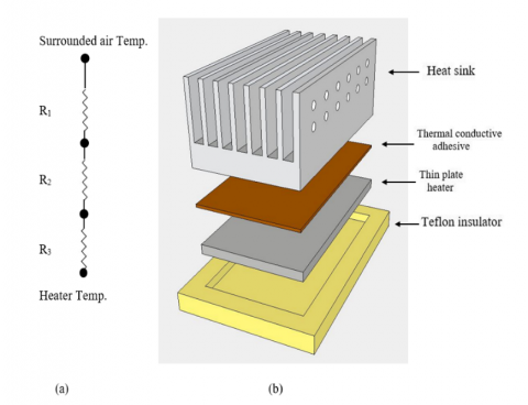
As it is clear in the Figure 8 there is a thermal resistance of each layer of the heating system, starting with the interface between heater and heat sink, as well as the resistance of whole heat sink (base, fins and fin spaces).
Figure 8. (a) Thermal resistances sketch (R1: Fin resistance, R2: Heat sink base, R3: Interface resistance); (b) Schematic of thermal system layers
In the current study, the thermal performance of the perforated heat sinks at different perforated sizes has been carried out. Then two models of these heat sinks are compared with the non-perforated one. For all types of heat sinks, the results are evaluated and discussed to show the effect of (a-changing air velocity, b-changing loads), it completely depends on the surface area of the heat sink and the pattern of perforation distribution on the fin.
4.1 Changing air velocity
4.1.1 Heat transfer (Q)
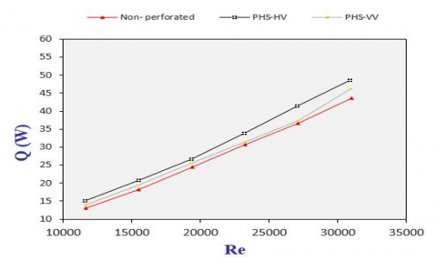
The heat dissipated from the heat sink to the surroundings is a very important parameter, which has been plotted as function Reynolds number as illustrated in Figure 9. For comparison between non-perforated and other types of the perforated plate-fin heat sink, it can be noticed that all types of perforated heat sinks have a values of heat dissipation higher than the solid plate-fin heat sink. This behavior is attributed to the perforation, which adds an extra area for heat exchange and speeds up the cooling of hot bodies. Moreover, as compared to other forms of heat sinks, PHS-HV has the highest rate of heat transfer. The solid heat sink, in comparison, has the lowest heat transfer rate value. For instant, the heat dissipated improves of PHS-HV heat sink by 8.53% while PHS-VV improves Q by 4.36% only at Re 20000. This can be attributed to the perforated fins' increased surface area for heat exchange, which is more than that of solid surfaces and results in a higher capacity for heat storage. Perforations make contacted air stay for a longer time due to vortex occurring at the hole area, and that prolongs exchanging heat process between the fin and flow air, thus accelerating the cooling of the perforated fin compared to the non–perforated fin.
Figure 9. The relation between Q and Re
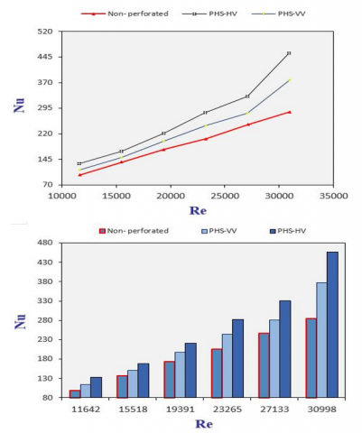
Figure 10. The relation between Nu and Re
4.1.2 Nusslet number (Nu)
It can be noticed from the Figure 10 that Nu increases with Re increasing- as Nu is a function of Re and Pr-. Nu has direct proportion with Re for all types of heat sinks (perforated and non-perforated), That can be attributed to the fact: with adding the perforations that turbulence increased which leads to enhance heat transfer. Moreover, the surface area increases with using a perforated heat sink instead of solid one. i.e. increase the heat dissipation from heat sink. This behavior is consistent with previous studies, such as [6, 16, 17]. In terms of perforation effect, it can be seen from the figure, that perforation increasing Nu. In the present study, at Re 20000 the Nu increase as (13.6%, 27.16%) for perforated heat sinks (PHS-VV, PHS-HV) respectively. In compared with solid heat sink, which gave lowest value of Nu, while PHS-HV has the highest value of Nu, because it cools the heat sink fast and help convective heat transfer to increase, that means increasing Nu- as Nu=(convection/conduction).
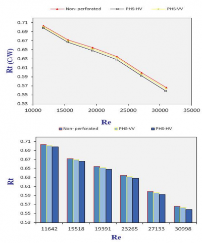
4.1.3 Thermal resistance (Rt)
The performance of the heat sink is significantly influenced by the thermal resistance. Figure 11 shows how the thermal resistance system behaves concerning perforation's diameter. This figure demonstrates how the thermal resistance decreases with increasing hole diameter for all types of heat sinks. This behavior may be explained by the fact that perforation increases surface area. As can be seen in the figure, the solid heat sink has the largest thermal resistance, while Rt decreases for PHS-HV and PHS-VV by (1.03%, 0.44%) respectively at Re 20000.
Figure 11. The relation between Rt and Re
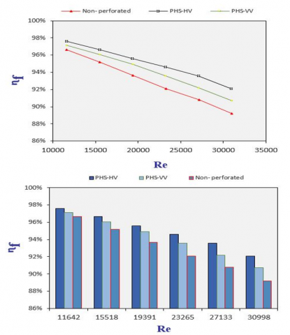
4.1.3 Fin efficiency (ƞf)
Figure 12 shows that the fins' efficiency decreases as Re increases; this behavior was similar to the outcomes shown by Shaeri et al. [6], Sahin and Demir [18]. This figure shows that as the fin diameter increases, the fin heat sink's efficiency rises. This, as previously stated, is due to the larger surface area provided by the larger fin diameter. Additionally, the PHS-HV heat sink's fins have the best efficiency, the enhancement ratio is (3.23%), whereas the PHS-VV has less than the first one (an enhancement ratio (1.7%) in comparison with non-perforated heat sink efficiency.
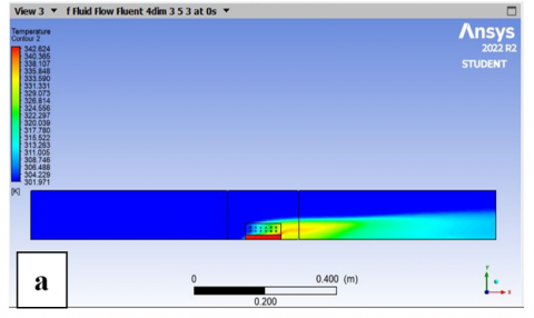
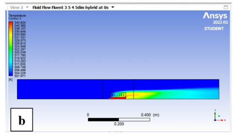
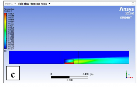
This perforation pattern (horizontal variation of hole diameter) gives an equal thermal distribution at all points of the heat sink, as shown in the Figure 13. When the cold air hits the front of the heat sink, the first fins of the heat sink will drop in temperature, while the end of the heat sink will be hotter because the passage of air over the heat sink is fast by using a speed. The time is not sufficient to conduct an equal heat exchange for all areas of the heat sink, as the beginning of the heat sink is colder than its end, and this is the aim of conducting this study. As it is known that the greater the diameter of the hole, the greater the surface area and the greater the exchange of heat with it, so the choice of holes with a smaller diameter in the front of the heatsink was not arbitrary, but rather came from the idea that the increase in the diameter of the holes is towards increasing the temperature of the heatsink, i.e. increasing the surface area of one fin in the region The hottest to ensure an even heat distribution along the fin, which in turn speeds up the heat expulsion process to the surrounding.
Figure 12. The relation between ƞf and Re
For the same reason, the second pattern (vertical variation of hole diameter), the lower part of the fin-nearest part to the heat source- is hotter than upper part. The bigger perforation diameter should be at lower part to ensure equal temperature distribution over the whole fin, which speed up heat removing from the heat sink to surrounding.
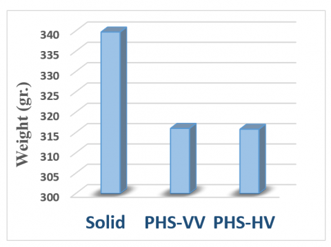
4.1.4 Weight reduction
The mass of the heat sink is very important for economic reasons; lighter heat sinks are preferable. The mass of the fin heat sink is a function of fin diameter, i.e., whenever perforation diameter increases the surface area increase and the heat sink weight decrease, as shown in Figure 14. It can be noted that the surface area is proportional inversely to the mass of the heat sink. This behavior explains that perforating the fins means removing parts from these fins, and that leads to reduce the mass of the fins. It can be seen from the figure that the PHS-VV reduced the weight by percentages (6.97%), while PHS-HV reduced by (7.03%) from the weight of the solid heat sink.
Figure 13. The temperature distribution for the heat sinks: (a) PHS-HV; (b) PHS-VV; (c) Non-perforated
Figure 14. Weight reduction for heat sink types
4.2 Changing thermal loads
All previous results were at constant voltage (80 v), this part will show the effect of changing the thermal loads supplied to the heat sinks (at constant air velocity 2.5 m/s) on the temperature distribution of the surface of the heat sink.
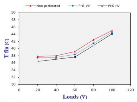
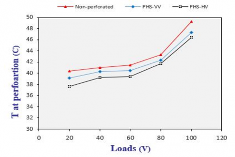
Figure 15. Relations between fin temperature and loads
4.2.1 Fin temperature
Different points on surface of heat sink fin were measured to investigate the influence of perforation generally and to show the effect of new perforation pattern on the fin temperature. Three locations were selected: at the top of the fin (Tfin), at the middle of the fin (T at perforation line), and at the fin base (Tbase). As cleared in Figure 15 the relation is direct, and all that points were get hotter when thermal loads- heat supplied by the electrical heater- increase, as it works to dissipate the excess heat. From the curves, the presence of holes at the fin increases the exchanging of heat with the surrounding air, and cooling the hot heat sink faster than the solid fin. For the comparison between the types of heat sinks used in this paper, the highest temperature rise occurs in the perforations area- at the middle of the fin-. Wherever the temperature difference between the fin and the surrounding increases, heat transfer and cooling of the body increase. This explains why expanding the diameters of the holes in a horizontal direction is better than expanding the diameters in a vertical direction, because it is the hottest part of the fin, working on cooling it has a positive effect by cooling the whole heat sink and removing its heat.
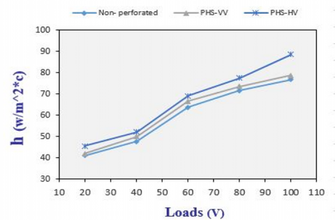
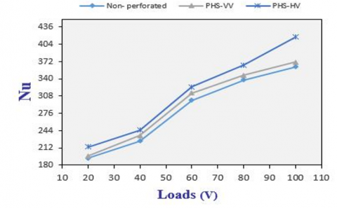
4.2.2 Nusslet number and heat transfer coefficient
The observed attitude of both Nu and h in the current study is that they go up with increasing thermal loads, as shown in Figures 16 and 17. At (80 V) perforated heat sinks PHS-VV and PHS-HV were made h values raised by (2.6%, and 8.16%) respectively. While Nu has been enhanced by (2.68%, and 8.73%) when using investigated heat sinks PHS-VV and PHS-HV respectively when compared with non-perforated heat sinks. The maximum value of h and Nu was gained when testing PHS-HV and the minimum value was recorded when testing the non-perforated heat sink.
Figure 16. Variation of h with loads
Figure 17. Variation of Nu with loads
When thermal load increases the temperature difference between hot body and its surrounding increases as well, which lead increasing in convective heat transfer. then increasing the value of h and Nu- as the Nusslet number is the ratio of convective to the conductive heat transfer within a fluid [15]. For perforated heat sinks, expanding the hole diameter in horizontal direction cooling the whole heat sink faster than PHS-VV.
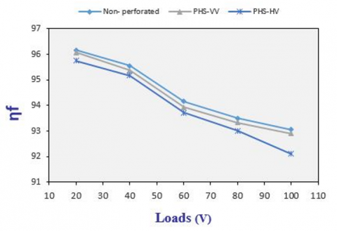
4.2.3 Fin performance ƞf
It is clear from Figure 18 the variation of fin performance as result of thermal load influence. The fin performance decrease with increasing thermal loads. Compared with the solid heat sink, the fin performance has been improved by (0.16%, and 1.02%) when testing perforated heat sinks (PHS-VV, PHS-HV) respectively at (100V). The heat sink (PHS-HV) had a higher overall thermal efficiency than other type. This is attributed that the perforated fin has a greater area- that contacted surrounding air- than the solid fin, and that leads to high heat dissipation.
Figure 18. Variation of fin performance with loads
The two perforation patterns of heat sink fins have been studied in this paper. PHS-HV and PHS-VV were used and compared with a solid heat sink. The effects of these patterns on the Nusslet number, convective heat transfer coefficient, thermal resistance, heat transfer rate, and performance of heat sink are determined and concluded as follows:
1- High value of heat transfer coefficient; heat dissipated, and fin efficiency with using perforated plate-fin heat sink instead of solid plate-fin heat sinks.
2- Using of different hole’s diameters in the same fin has a positive effect on the heat dissipation, and that the expand the hole's diameter in the horizontal direction (PHS-HV) is better than the expand of the diameters in the vertical direction (PHS-VV). The improving of heat transfer was 8.53% for PHS-HV, while PHS_VV had an improvement of 4.36% only at Re 20000.
3- compared to other forms of heat sinks, PHS-HV has the highest improvement of heat transfer coefficient 23.15%.
4- Thermal resistance decrease with using PHS-HV and PHS-VV compared with a solid heat sink.
5- The maximum weight reduction achieved by PHS-HV, which reduced by 7.03%, while PHS-VV reduction was 6.97% compared with a solid heat sink.
In summary, enlarging the diameter of the holes in the horizontal direction of the fin is better at dissipating heat than enlarging the diameter in the vertical direction lead to conclude that the hot part that is generated in the second half of the heatsink (as well as the heat that is generated behind the heatsink) is greater than the hot part at the base of the fin, therefore, increasing the cooling of this part has a positive effect in increasing the rate of heat dissipation.
|
Q |
Heat transfer |
|
hav |
Average heat transfer coefficient |
|
T |
Temperature |
|
Ts |
Surface temperature |
|
Tꝏ |
Mean temperature |
|
Tin |
Temperature at inlet area |
|
Tout |
Temperature at outlet area |
|
Tm |
Mean temperature |
|
ΔT |
Temperature difference |
|
W |
Duct cross section width |
|
A |
Area |
|
Ac |
Cross sectional area |
|
As |
Surface area |
|
Asf |
Surface area of fin |
|
Ass |
Surface area of fin space |
|
Ap |
Perforation area |
|
Np |
Perforation number |
|
Nf |
Fins number |
|
Wf |
Fin width (fin thickness) |
|
Lf |
Fin length |
|
Hf |
Fin height |
|
Q ̇conv. |
Convective heat transfer |
|
Q ̇cond. |
Conductive heat transfer |
|
Q ̇rad. |
Radiative heat transfer |
|
Q ̇elect. |
Electric heat transfer |
|
I |
Current |
|
V |
Voltage |
|
v |
Air velocity |
|
K |
Thermal conductivity |
|
Re |
Reynolds number |
|
Nu |
Nusslet number |
|
Pr |
Prandtle number |
|
m |
Mass |
|
m ̇ |
Mass flow rate |
|
Cp |
Specific heat at constant pressure |
|
Pp |
Perforation perimeter |
|
Dp |
Perforation diameter |
|
Ah |
Hole area |
|
Ns |
Space number |
|
R |
Thermal resistance |
|
Ad |
Cross-sectional area of duct |
|
Pd |
Perimeter of duct |
|
dh |
Hydraulic diameter |
|
Rcond. |
Conductive resistance |
|
Rconv. |
Convective resistance |
|
Greek symbols |
|
|
Ø |
Hole diameter (perforation) |
|
ν |
Kinematic viscosity, m2.s-1 |
|
ꝭair |
Density of air, kg.m-3 |
|
Ƞ |
Thermal efficiency |
|
ɛf |
Fin effectiveness |
|
$\Theta b$ |
Temperature difference |
|
Subscripts |
|
|
Av |
Average |
|
Base |
Heat sink base |
|
Fin, Fins |
Heat sink fin |
|
In |
Inlet |
|
Out |
Outlet |
|
M |
Mean |
|
ꝏ |
Infinity |
|
Re |
Reynolds number |
|
Nu |
Nusslet number |
|
Pr |
Prandtle number |
[1] Chingulpitak, S., Wongwises, S. (2015). A review of the effect of flow directions and behaviours on the thermal performance of conventional heat sinks. International Journal of Heat and Mass Transfer, 81: 10-18. https://doi.org/10.1016/j.ijheatmasstransfer.2014.09.081
[2] Shyu, J.C., Jheng, J.S. (2020). Heat transfer enhancement of plate-fin heat sinks with different types of winglet vortex generators. Energies, 13(19): 5219. https://doi.org/10.3390/en13195219
[3] Wang, W., Li, Y.J., Zhang, Y.N., Li, B.X., Sundén, B. (2020). Analysis of laminar flow and heat transfer in an interrupted microchannel heat sink with different shaped ribs. Journal of Thermal Analysis and Calorimetry, 140: 1259-1266. https://doi.org/10.1007/s10973-019-09156-x
[4] Zhu, Q.F., Jin, Y.Y., Chen, J.J. (2021). Computational study of rib shape and configuration for heat transfer and fluid flow characteristics of microchannel heat sinks with fan-shaped cavities. Applied Thermal Engineering, 195: 117171. https://doi.org/10.1016/j.applthermaleng.2021.117171
[5] Sara, O.N., Pekdemir, T., Yapici, S., Yilmaz, M. (2001). Heat-transfer enhancement in a channel flow with perforated rectangular blocks. International Journal of Heat and Fluid Flow, 22(5): 509-518. https://doi.org/10.1016/S0142-727X(01)00117-5
[6] Shaeri, M.R., Yaghoubi, M., Jafarpur, K. (2009). Heat transfer analysis of lateral perforated fin heat sinks. Applied Energy, 86(10): 2019-2029. https://doi.org/10.1016/j.apenergy.2008.12.029
[7] Venkitaraj, K.P., Sanooj, S. (2016). Natural convection heat transfer enhancement from rectangular fin arrays with divers geometrical perforations. 2016 International Conference on Energy Efficient Technologies for Sustainability (ICEETS), Nagercoil, India. pp. 711-716. https://doi.org/10.1109/ICEETS.2016.7583842
[8] Sonawane, R., Palande, D.D. (2016). Heat transfer enhancement by using perforation: A review. International Research Journal of Engineering and Technology, 3(4): 2624-2629.
[9] Shaeri, M.R., Bonner, R. (2017). Laminar forced convection heat transfers from laterally perforated-finned heat sinks. Applied Thermal Engineering, 116: 406-418. https://doi.org/10.1016/j.applthermaleng.2016.12.103
[10] Chingulpitak, S., Ahn, H.S., Asirvatham, L.G., Wongwises, S. (2019). Fluid flow and heat transfer characteristics of heat sinks with laterally perforated plate fins. International Journal of Heat and Mass Transfer, 138: 293-303. https://doi.org/10.1016/j.ijheatmasstransfer.2019.04.027
[11] Huang, C.H., Huang, Y.R. (2021). An optimum design problem in estimating the shape of perforated pins and splitters in a plate-pin-fin heat sink. International Journal of Thermal Science, 170: 107096. https://doi.org/10.1016/j.ijthermalsci.2021.107096
[12] Dhanawade, K.H., Sunnapwar, V.K., Dhanawade, H.S. (2014). Thermal analysis of square and circular perforated fin arrays by forced convection. International Journal of Current Engineering and Technology, 2: 109-114. http://dx.doi.org/10.14741/ijcet/spl.2.2014.20
[13] Lee, H.S. (2011). Thermal Design. 2nd Edition, Hoboken, New Jersey, John Wiley and Sons.
[14] Al-Damook, A.J.S. (2016) Design optimization and analysis of heat sinks for electronic cooling. University of Leeds (iTF).
[15] Ehteshum, M., Ali, M., Islam, M.Q., Tabassum, M. (2015). Thermal and hydraulic performance analysis of rectangular fin arrays with perforation size and number. Procedia Engineering, 105: 184-191. https://doi.org/10.1016/j.proeng.2015.05.054
[16] Ismail, M.F., Hasan, M.N., Saha, S.C. (2014). Numerical study of turbulent fluid flow and heat transfer in lateral perforated extended surfaces. Energy, 64: 632-639. https://doi.org/10.1016/j.energy.2013.10.079
[17] Haque, M.R., Hridi, T.J., Haque, M.M. (2022). CFD studies on thermal performance augmentation of heat sink using perforated twisted, and grooved pin fins. International Journal of Thermal Science, 182: 107832. https://doi.org/10.1016/j.ijthermalsci.2022.107832
[18] Sahin, B., Demir, A. (2008). Performance analysis of a heat exchanger having perforated square fins. Applied Thermal Engineering, 28(5-6): 621-632. https://doi.org/10.1016/j.applthermaleng.2007.04.003