Ihsan Z. Salim*![]() | Najim A. Jassim
| Najim A. Jassim![]()
© 2023 IIETA. This article is published by IIETA and is licensed under the CC BY 4.0 license (http://creativecommons.org/licenses/by/4.0/).
OPEN ACCESS
The steam ejector, an essential auxiliary device, finds extensive use in various applications, including Multiple Effect Evaporation Desalination systems. The present study endeavored to evaluate the impact of different Converging-Diverging Nozzle placements. Initially, a vapor ejection was designed under certain conditions, utilizing one-dimensional compressible flow equations. Subsequently, the flow within the vapor ejection was simulated via a computational fluid dynamics (CFD) application, specifically the ANSYS program. The investigation entailed the selection of multiple nozzle locations and the examination of their effects under two scenarios: one with a constant back pressure for various suction pressures at each nozzle location, and the other with a fixed suction pressure coupled with several exit pressures. Results from the first scenario indicated that the optimal nozzle location was 5 mm from the commencement of the mixing area. For the second scenario, it was observed that closer proximity of the nozzle to the mixing area enhanced the performance of the steam ejector.
Converging-Diverging Nozzle, desalination, mixer, steam ejector
The steam ejector, a critical application of both compressible and incompressible flow, operates on the principles of suction and pressure of fluids, negating the necessity for moving parts that could potentially be impacted by the fluid traversing the compressor or pump. In a steam ejector, a high-velocity fluid jet is mixed with a second fluid, with the resultant mixture discharged into an area at a pressure exceeding that of the second fluid source. This mechanism enables the steam ejector to pump fluid from one location to another [1, 2].
A key application of the steam ejector is found within the multiple-effect evaporation desalination system, where it is utilized to maintain vacuum levels and eliminate non-condensable gases from the cascade effects and low-pressure condenser [3]. This contributes to a reduction in the water boiling temperature to below 100℃, thereby mitigating heat losses in the system by decreasing the temperature difference between the water in the evaporator, pre-heat water, and ambient temperature. Consequently, the energy required for steam generation is also reduced.
When the propelled fluids are gases, such as steam and air, the ejector's performance becomes more complex compared to when the propelled fluid is a liquid. This complexity arises from the gas density changes due to compressibility and temperature fluctuations inside the launcher, leading to new phenomena. When a Converging-Diverging Nozzle is employed, the gas velocity exiting the nozzle typically exceeds the speed of sound in the propellant gas at the given temperature. Post-mixing, the fluid velocity often remains supersonic, and compression shock takes place in the diffuser [1].
Following the initial stages, the mixture progresses through the throttling area, the diameter of which is designed in accordance with the volume of fluid passing through it. This calculation is executed as a one-dimensional flow. The length of the throttling channel is contingent upon the flow consistency and the optimization of the overall performance of the steam injector system.
Numerous researchers have investigated various factors influencing the performance of the steam ejector and have sought to enhance its efficiency. Studies have examined the implications of the shape and dimensions of the steam ejector, as undertaken by Yang et al. [4], who explored the influence of the primary nozzle area ratio on steam ejector performance, accounting for nonequilibrium condensations. The development of two-dimensional convergent-divergent nozzle performance was analyzed in a rapid analysis project [5]. Furthermore, A.S. Hanafi conducted a study involving 1-D mathematical modelling and a CFD investigation on a supersonic steam ejector in MED-TVC [2]. Bi et al. [6] also evaluated the effect of throat length on steam ejector critical back pressure.
Shahzamanian et al. [7] presented a study titled "Performance Evaluation of a Variable Geometry Ejector Applied in a Multi-Effect Thermal Vapour Compression Desalination System". The research centered on the engineering modification of a steam ejector by employing computational fluid dynamics simulation, considering each shape across a range of operating temperatures for the initial flow. The findings indicated that relatively high initial inlet temperatures undergo significant expansion post-nozzle exit, and the nozzle exit position influences the ejector performance by approximately 16% within the studied range.
Al-Manea and Al-Jadir [8] conducted a study investigating the influence of ejector design parameters on the internal flow structure within the mixing chamber. A computational fluid dynamics (CFD) numerical simulation was employed to examine the impact of various design parameters on the flow structure within an ejector. Three mesh sizes were proposed, with the medium size being selected for consideration. The results revealed that the adoption of a secondary inlet with a diameter of 90 mm led to a decrease in the generation of vortices compared to Model I. Additionally, the modification of the diffuser throat to 45 mm in Model II was observed to enhance vortex reduction.
Additional studies have investigated the degree to which steam ejector performance is influenced by operational conditions and the specific fluid utilized, given the variations in the fluid's physical properties within the vapor ejector. For instance, Li et al. [9] conducted a computational study of wet steam flow with the objective of optimizing steam ejector efficiency for potential fire suppression applications. It was concluded that decreasing the wetness of the secondary inlet flow could potentially optimize system performance, signified by a substantial increase in the entrainment ratio. Riaz et al. [10] similarly conducted direct analytical modeling for optimal, on-design performance of an ejector for simulating heat-driven systems. Li et al. [11] examined the effect of different pressure conditions on shock waves in a supersonic steam ejector, demonstrating that the intensity and number of oblique shock waves in the diffuser increase with an elevation in motive pressure and suction pressure, or a reduction in discharge pressure. Despite these studies focusing on the shape and dimensions of the steam ejector or the impact of operating conditions, the effect of nozzle location has not been addressed.
The present study aims to explore the influence of the initial nozzle's location within the mixing chamber on the performance of the steam ejector. Specifically, the study investigates the effects of altering the nozzle's position on the pressures required to achieve the lowest possible pressure, thus optimizing the steam ejector's operation. This involves ensuring an ideal flow within the steam ejector.
To achieve the research objectives of knowing the location of the nozzle inside the steam ejector on the necessary injection pressure values at the identical dimensions of the steam ejector. The first stage will include designing the steam ejector, using one-dimensional gas dynamics equations to calculate all diameters of the steam ejector [2]. The second stage includes the flow inside the steam ejector simulation based on the dimensions obtained from the first stage, which is carried through the CFD system using the ANSYS program [12].
2.1 One-dimensional gas dynamics calculation
For normal and stable operation of the steam jet see Figure 1, it must be designed under critical conditions, the design of the continuous pressure ejector was based on several assumptions, which are summarized as follows [13]:
The ejector flow is one-dimensional and at steady state conditions.
a) The flow is adiabatic, so that there is no heat transfer between the fluids inside ejector and the surrounding.
b) Steam follows ideal gas behavior.
c) Friction losses in the nozzle, diffuser, and mixing chamber are taken into account within the efficiency of each part.
d) The velocities of the motive steam and the entrained vapor are negligible because it comes from relatively large tanks.
e) Constant isentropic expansion exponent and the ideal gas behavior.
f) The motive steam and the entrained vapor have the same physical properties.
Figure 1. Steam ejector scheme
The steam ejector is designed according to the following steps see Figure 2.
Figure 2. Scheme of the algorithm for the calculation process of steam ejector
The following is an explanation of the steam ejector calculation equations according to the above model:
1) Design parameters, and calculation flow rates of motive steam and entrained vapor:
$m_p+m_e=m_c$ (1)
where,
mp: Primary stream mass flow rate $\left(\frac{\mathrm{kg}}{\mathrm{s}}\right)$.
me: Entrained vapor mass flow rate (kg/s).
mc: Compressed vapor mixture mass flow rate (kg/s).
$w=\frac{m_e}{m_p}$ (2)
2) Calculation the Mach numbers:
The Mach number of the primary fluid at the nozzle outlet level. This will be calculated by assuming the initial value of the pressure at the Converging–Diverging Nozzle outlet.
$M_{P 2}=\sqrt{\frac{2 \eta_n}{(\gamma-1)}\left[\left(\frac{P_p}{P_2}\right)^{\frac{(\gamma-1)}{\gamma}}-1\right]}$ (3)
$M_{P 2}{ }^*=\sqrt{\frac{M_{P 2}{ }^2(\gamma+1)}{M_{P 2}{ }^2(\gamma-1)+2}}$ (4)
where,
γ: is the isentropic expansion coefficient.
ηn: is the nozzle efficiency.
M*: is the ratio between the local fluid velocity to the velocity of sound at critical conditions.
The same applies to the secondary fluid:
$M_{e 2}=\sqrt{\frac{2}{(\gamma-1)}\left[\left(\frac{P_e}{P_2}\right)^{\frac{(\gamma-1)}{\gamma}}-1\right]}$ (5)
$M_{e 2}{ }^*=\sqrt{\frac{M_{e 2}{ }^2(\gamma+1)}{{M_{e 2}}^2(\gamma-1)+2}}$ (6)
Using the one-dimensional continuity equation and momentum-energy equations for the compressible flow. The critical Mach number of the mixture at point (5) is calculated using:
$M_4{ }^*=\frac{M_{P 2}{ }^*+w M_{e 2}{ }^* \sqrt{T_e / T_p}}{\sqrt{(1+w)\left(1+w T_e / T_p\right)}}$ (7)
$M_4=\sqrt{\frac{2 M_4{ }^{* 2}}{(\gamma+1)-M_4{ }^{* 2}(\gamma-1)}}$ (8)
$M_5^2=\frac{M_4^2+\frac{2}{(\gamma-1)}}{\frac{2}{(\gamma-1)} M_4^2-1}$ (9)
3) Check the pressure value at point (2):
$P_5 / P_4=\frac{1+\gamma M_4^2}{1+\gamma M_5^2}$ (10)
• Assuming that the pressure remains constant at points (2, 3 and 4). So, the pressure at the exit of the steam ejector (at point c) is:
$P_c / P_5=\left[\frac{\eta_d(\gamma-1)}{2} M_5^2+1\right]^{\frac{\gamma}{\gamma-1}}$ (11)
where,
ηd: is the diffuser efficiency.
Through the results obtained, it is checked whether the pressure value at point c matches what was obtained. The calculations are repeated for the pressure values according to equations from (3) to (11) until a match in the values is reached at point c.
4) Calculate the cross-sectional areas of the steam ejector.
• Calculate the cross-sectional area at the throat of Converging–Diverging Nozzle:
$A_1=\frac{m_p}{P_p} \sqrt{\frac{R T_p}{\gamma \eta_n}\left(\frac{\gamma+1}{2}\right)^{\frac{(\gamma+1)}{(\gamma-1)}}}$ (12)
• Calculate the cross-sectional area at the exit of the Converging–Diverging Nozzle:
$A_2 / A_1=\frac{1}{M_{P 2}}\left(\frac{1+\frac{(\gamma-1) M_{P 2}{ }^2}{2}}{\frac{(\gamma+1)}{2}}\right)^{\frac{(\gamma+1)}{2(\gamma-1)}}$ (13)
• The area ratio of the nozzle throat (point 1) and diffuser constant area (point 3):
$\begin{aligned} & A_1 / A_3=\frac{P_c}{P_p}\left(\frac{1}{(1+w)\left(1+w\left(\frac{P_e}{P_p}\right)\right)}\right)^{1 / 2} \frac{\left(\frac{P_2}{P_c}\right)^{1 / \gamma}\left(1-\left(\frac{P_2}{P_c}\right)^{\frac{(\gamma-1)}{\gamma}}\right)^{1 / 2}}{\left(\frac{2}{\gamma+1}\right)^{1 /(\gamma-1)}\left(1-\frac{2}{\gamma+1}\right)^{1 / 2}}\end{aligned}$ (14)
Through the calculations that were made using the above equations, all the cross-sectional areas of each part of the steam ejector were obtained. As for the lengths of the parts. The correctness inclination angle of the diffuser is less than 10 degrees was adopted for the publisher in each of the primary Converging-Diverging Nozzle and the region Mixing As for the suffocation area [5, 6, 14], certain lengths were adopted commensurate with the mixing stability (for the mixing area) [6], and accordingly all the dimensions of the steam ejector were obtained and were as in Table 1.
The current model's primary flow is superheated steam at total pressure (7.5 bar), temperature (175℃) and mass flow rate of superheated steam (0.02 kg/s). The steam condition in the suction area at pressure (0.65 bar) and temperature (84℃). The amount of steam entering was about (0.01). In the discharge condition, the vapour is superheated steam at pressure (0.15 bar) and temperature (96℃).
The isentropic expansion coefficient for steam flowing through the ejector approximately is (γ=1.3) [15], as well as the nozzle efficiency (ηn=0.9) and the diffuser efficiency (ηd=0.8) [13].
Table 1. Geometrical parameters of the steam ejector
|
Parameter |
Size (mm) |
|
Inlet diameter of the primary nozzle |
12 |
|
Throat diameter of the primary nozzle |
2.4 |
|
Outlet diameter of the primary nozzle |
6 |
|
Length of the converging part of the primary nozzle |
15 |
|
Length of the diverging part of the primary nozzle |
20 |
|
Inlet diameter of the mixing chamber |
50 |
|
Length of the mixing chamber |
70 |
|
Diameter of the constant section |
14 |
|
Length of the constant section |
50 |
|
Outlet diameter of the diffuser |
24 |
|
Length of the diffuser |
85 |
2.2 CFD modeling
The flow pattern within a steady-state steam ejector and a compressible fluid can be represented by the continuity equations with Navier-Stokes in addition to Reynolds averaging and the energy equation and as follows [12]:
a) Continuity equation:
$\frac{\partial}{\partial x_i}\left(\rho u_i\right)=0$ (15)
b) Navier-Stokes equation:
$\begin{aligned} \frac{\partial}{\partial x_i}\left(\rho u_i u_i\right)=- & \frac{\partial p}{\partial x_i}+\frac{\partial}{\partial x_j}\left[\mu\left(\frac{\partial u_i}{\partial x_j}+\frac{\partial u_j}{\partial x_i}\right.\right.\left.\left.-\frac{2}{3} \delta_{i j} \frac{\partial u_k}{\partial x_k}\right)\right]+\frac{\partial}{\partial x_j}\left(-\rho \overline{u_i^{\prime} u_j^{\prime}}\right)\end{aligned}$ (16)
c) Energy equation:
$\frac{\partial}{\partial x_i}\left(\rho c_p u_i T\right)=\frac{\partial}{\partial x_i}\left(\lambda \frac{\partial T}{\partial x_i}-\rho c_p \overline{u_l^{\prime} T^{\prime}}\right)+\mu \phi$ (17)
where,
$\rho \overline{u_l^{\prime} u_l^{\prime}}$ : Reynolds stresses.
$\rho c_p \overline{u_i^{\prime} T^{\prime}}$ : Turbulent heat fluxe.
λ: The heat conductivity.
μϕ: The viscous dissipation.
In this simulation, the realizable (k-ε) turbulence model is used to represent the turbulence features, based on previous literature, Hanafi used a turbulence model to represent the flow inside the steam ejector, which demonstrated better agreement with experimental data and more accuracy in forecasting the spreading rate of both planar and round jets. In their compact Cartesian form, the transport equations for (k-ε) are as follows [2].
$\begin{aligned} & \frac{\partial}{\partial t}(\rho K)+\frac{\partial}{\partial x_i}\left(\rho K u_i\right) =\frac{\partial}{\partial x_j}\left[\left(\mu+\frac{\mu_t}{\sigma_k}\right) \frac{\partial k}{\partial x_j}\right]+G_k-\rho \varepsilon-Y_M\end{aligned}$ (18)
$\begin{aligned} \frac{\partial(\rho \varepsilon)}{\partial t}+\frac{\partial\left(\rho \varepsilon u_i\right)}{\partial x_i}= & \frac{\partial}{\partial x_j}\left[\left(\mu+\frac{\mu_t}{\sigma_{\varepsilon}}\right) \frac{\partial \varepsilon}{\partial x_j}\right]+\rho C_1 S_{\varepsilon}-\rho C_2 \frac{\varepsilon^2}{K+\sqrt{\nu \varepsilon}}+C_{1 \varepsilon} \frac{\varepsilon}{K} C_{e \varepsilon} C G_b\end{aligned}$ (19)
where,
$C_1=\max \left[0.43 \frac{\eta}{\eta+5}\right]$ (20)
$\eta=S K \varepsilon$ (21)
$\mu_t=\rho C_\mu \frac{K^2}{\varepsilon}$ (22)
Note:
C1=1.44 (constant).
C2=1.9 (constant).
σk=1.0 (the turbulent Prandtl numbers for k).
σε=1.2 (the turbulent Prandtl numbers for ε).
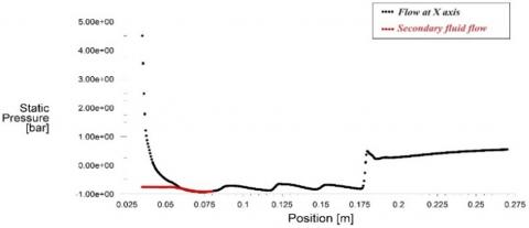
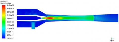
By representing the flow using the ANSYS program and with the exact flow specifications mentioned in the previous paragraph, the turbulent flow type (k-ε) was adopted, and accordingly, the amount of pressure and velocity at the central axis of the steam ejector. In this work, we relied on representing the flow using the ANSYS program only to determine whether the flow inside the steam ejector works within the design conditions, represented in Figure 3 and Figure 4, were obtained, respectively, in addition to the shape of the flow inside the steam ejector (represented by the velocity vector) see Figure 5, which shows the location of the shock wave at the entrance of the diffuser. The steam velocity at the outlet of the internal nozzle reaches about (440 m/s), while in the vacuum chamber, the velocity is less than (45m/s) and at the steam ejector outlet, it is at a rate of (50 m/s).
Figure 3. Pressure inside the steam ejector
Figure 4. Mach number inside the steam ejector
Figure 5. Flow inside the steam ejector (represented by the Mach number)
The current steam ejector is part of a water desalination system with a predetermined throughput, and the steam ejector is designed based on the amount of steam as well as the operating conditions, so it is challenging to compare the results of the dimensions of the steam ejector in this work with previous literature.
2.3 The primary nozzle location effect calculation
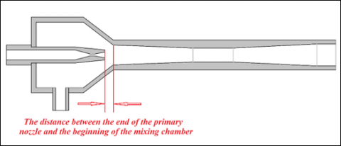
After completing the design of the steam ejector and obtaining all the required dimensions, as mentioned in the previous two paragraphs, it is now the turn to find out the best location for the primary nozzle in relation to the mixing area shown in Figure 6 and its effect on the pressure required for injection (primary stream pressure Pp) in addition to its effect on the amount of steam withdrawn from the area suction. The previous design of the steam ejector was tested at the same pressure in the suction area (entrained vapor pressure Pe) as well as the pressure at the end of the steam injector (compressed vapor pressure Pc).
Figure 6. The distance between the primary nozzle and the mixing chamber
Using the values of the initial pressure and through equation No. 12, the mass of vapor passing through the primary nozzle can be calculated according to the equation:
$m_p=P_p A_1 \sqrt{\frac{\gamma}{R T_p}\left(\frac{2}{\gamma+1}\right)^{\frac{(\gamma+1)}{(\gamma-1)}}}$ (23)
Since the design of the steam ejector relied on its best performance, which requires that the location of the shock wave at the start of the diffuser be at point (5) and immediately after the constant area, through the values obtained when representing the flow using CFD at each of the primary nozzle locations inside the vapor ejector.
Depending on the pressure values at point 2, the amount of steam entering from the suction area is calculated, then:
$m_e=\rho_{e 2} V_{e 2} A_{e 2}$ (24)
where:
$\rho_{e 2}=\frac{P_{e z}}{R T_{e 2}}$ (25)
$V_{e 2}=M_{e 2} a_{e 2}$ (26)
$a_{e 2}=\sqrt{\gamma R T_{e 2}}$ (27)
From Eq. (7)
$M_{e 2}=\sqrt{\frac{2}{(\gamma-1)}\left[\left(\frac{P_e}{P_2}\right)^{\frac{(\gamma-1)}{\gamma}}-1\right]}$ (28)
Also:
$T_e / T_{e 2}=\left\lceil\frac{(\gamma-1)}{2} M_{e 2}^2+1\right\rceil$ (29)
So
$m_e=P_{e 2} M_{e 2} A_{e 2} \sqrt{\frac{\gamma}{R T_{e 2}}}$ (30)
Note: The values of the area (Ae2) were calculated from the internal area of the steam ejector minus the area of the external nozzle at point 2, and Figure 7 shows the area that the secondary fluid passes through in the suction area, where:
$A_{e 2}=A_{l-E j}-A_{O-N o z} C$ (31)
Or
$A_{e 2}=\frac{\pi}{4}\left(D_{l-E j}^2-D_{O-N o z}^2\right)$ (32)
Figure 7. Cross Section Area (Ae2) for secondary fluid at point (2)
In order be able to know the extent of the effect the nozzle location on the efficiency of the steam ejector, which is the ratio of the compressed secondary fluid one of the most important measures of performance efficiency, the percentage of the secondary fluid quantity to the total fluid amount must be calculated through:
$M F_e=\frac{m_e}{m_c}=\frac{m_e}{m_p+m_e}$ (33)
The results obtained from the simulation of the flow inside the steam ejector, which is necessary to complete the process in the best way, begin to decrease after moving the initial nozzle back from a distance (0 mm) to (5 mm), which means that the distance between the initial nozzle and the beginning of the mixing area.
When the primary nozzle is more than (5 mm) removed, the pressure gradually increases as the primary nozzle moves away from the mixing area. Therefore, it appears that the best distance for the initial nozzle from the mixing area is (5 mm).
The above process was repeated more than once at different values of pressure in the suction area, and a match appeared for all cases, as shown in Figure 8. (primary stream pressure Pp) versus the distance between the end of the primary nozzle and the beginning of the mixing chamber at different values. The minimum pressure required for the regular operation of the steam ejector is (5.5 kg/cm2) when the suction pressure is around (0.4 kg/cm2) and at a distance of (5 mm) from the beginning of the mixing area.
Figure 8. Primary flow pressure versus the distance between the end of the primary nozzle and the beginning of the mixing chamber
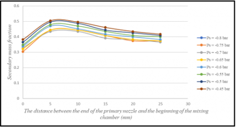
The pressure in the suction area decreases when the injection pressure increases, and thus the amount of steam generated in the evaporator increases to compensate for the decrease in the amount of steam passing through the primary nozzle according to Eq. (28), and this, in turn, means an increase in the efficiency of the evaporation system at the same temperatures as well as an increase in the mass fraction of the secondary fluid, as shown in the Figure 9.
The percentage increase in mass fraction was approximately (45.74%) when the edge of the nozzle was at a distance of (5 mm) from the beginning of the mixing zone. The value of mass fraction was (0.443), compared to the lowest mass fraction at a distance of (0 mm), which is (0.304) when the nozzle opening is at the beginning of the mixing zone.
Figure 9. Secondary mass fraction versus the distance between the end of the primary nozzle and the beginning of the mixing chamber
Figure 10. Primary flow pressure versus the distance between the end of the primary nozzle and the beginning of the mixing chamber
Figure 11. Primary flow pressure versus the distance between the end of the primary nozzle and the beginning of the mixing chamber
In contrast to what appeared in the tests of changing the position of the initial nozzle, the best location for the exit nozzle of the first nozzle is at a distance of (0 mm) in the case of pressure change at the outlet of the steam ejector when the value of the suction pressure is constant, in which the injection pressure required to reach the specified injection pressure at this distance is less What is possible and begins to increase gradually as the exit edge in the first nozzle moves away from the beginning of the mixing chamber, as shown in the Figure 10 Which shows the relationship between the location of the initial nozzle (the distance between the exit nozzle of the initial nozzle and the beginning of the mixing chamber) and the pressure required for injection (primary stream pressure Pp) at different values of the pressure exiting the steam ejector (compressed vapor pressure Pc), Of course it also applies to the mass fraction of the secondary fluid according to what is shown in the Figure 11.
This study included the result of flow analysis for steam ejector using the CFD model of the flow. The effect of the location of the initial nozzle inside the steam ejector is evident in the suction pressure, As well as the amount of steam removed from the container of vacuum pressure. The following conclusions are drawn based on the calculation:
The use of the steam ejector determines the best location for the primary nozzle has been located. The purpose of a steam ejector is to increase steam generation in a multi-effect evaporation desalination system. So, Prefer the primary nozzle placed at a distance of (5 mm).
Many factors affect the performance of the steam ejector, including what was discussed in previous research and the proposal in the current paper. Examining the effect of more than one factor at the same time on the performance of the steam ejector would play a role in obtaining better results. Therefore, it was suggested that the following effects be studied:
|
CFD |
computational fluid dynamics |
|
A |
Cross-sectional area m2 |
|
Cr |
Compression ratio |
|
Er |
Expansion ratio |
|
m |
mass flow rate kg.s-1 |
|
M |
Mach number (ratio between the fluid velocity to the velocity of sound). |
|
M* |
ratio between the local fluid velocity to the velocity of sound at critical conditions. |
|
P |
Pressure bar |
|
R |
Universal gas constant kJ. kg-1. K-1 |
|
T |
Temperature (K) |
|
V |
Velocity m.s-1 |
|
w |
Entrainment ratio |
|
Greek symbols |
|
|
γ |
Isentropic expansion |
|
ρ |
Density kg.m-3 |
|
ηd |
Diffuser Efficiency |
|
ηn |
Nozzle Efficiency |
|
µ |
dynamic viscosity, kg. m-1.s-1 |
|
Subscripts |
|
|
1 |
primary nozzle throttle |
|
2 |
primary nozzle exit |
|
3 |
entrance of the constant-area section |
|
4 |
exit of the constant-area section |
|
5 |
normal shock wave location in secondary nozzle |
|
c |
secondary nozzle exit (compressed vapor mixture) |
|
e |
The entrained vapor |
|
p |
The primary motive steam |
|
I-Ej. |
The inner border of the steam ejector |
|
O-Noz. |
The outer border of the primary nozzle |
[1] Power, R.B. (2005). Steam Jet Ejectors for the Process Industries. https://doi.org/10.1115/1.884829
[2] Hanafi, A.S., Mostafa, G.M., Waheed, A., Fathy, A. (2015). 1-D mathematical modeling and CFD Investigation on Supersonic Steam Ejector in MED-TVC. Energy Procedia, 75: 3239-3252. https://doi.org/10.1016/j.egypro.2015.07.690
[3] Schlichting, D.H. (1979). Boundary Layer -Theory. McGraw Hill Book Company.
[4] Yang, Y., Karvounis, N., Walther, J.H., Ding, H., Wen, C. (2021). Effect of area ratio of the primary nozzle on steam ejector performance considering nonequilibrium condensations. Energy, 237: 121483. https://doi.org/10.1016/j.energy.2021.121483
[5] Yang, Y.X., Qitai, E., Wang, Q., Zhu, X.J. (2015). Development of two-dimensional convergent-divergent nozzle performance rapidly analysis project. In Proceedings of the 2015 International Forum on Energy, Environment Science and Materials, pp. 882-887. https://doi.org/10.2991/ifeesm-15.2015.162
[6] Bi, R., Hu, M., Wang, S., Tan, X., Zheng, S. (2017). Effect of throat length on steam ejector critical back pressure. Chemical Engineering Transactions, 61: 1945-1950. https://doi.org/10.3303/CET1761322
[7] Shahzamanian, B., Varga, S., Soares, J., Palmero-Marrero, A.I., Oliveira, A.C. (2021). Performance evaluation of a variable geometry ejector applied in a multi-effect thermal vapor compression desalination system. Applied Thermal Engineering, 195: 117177. https://doi.org/10.1016/j.applthermaleng.2021.117177
[8] Al-Manea, A., Al-Jadir, T. (2021). Effect of ejector design parameters on flow structure inside the mixing chamber. IOP Conference Series: Earth and Environmental Science, 779: 012033. https://doi.org/10.1088/1755-1315/779/1/012033
[9] Li. A., Yuen, A.C.Y., Chen, T.B.Y., Wang, C., Liu, H.R., Cao, R.F., Yang, W., Yeoh, G.H., Timchenko, V. (2019). Computational study of wet steam flow to optimize steam ejector efficiency for potential fire suppression application. Applied Sciences, 9(7): 1468. https://doi.org/10.3390/app9071486
[10] Riaz, F., Yam, F.Z., Qyyum, M.A., Shahzad, M.W., Farooq, M., Lee, P.S., Lee, M. (2021). Direct analytical modeling for optimal, on-design performance of ejector for simulating heat-driven systems. Energies, 14(10): 2819. https://doi.org/10.3390/en14102819
[11] Li, Y., Shen, S., Niu, C., Guo, Y., Zhang, L. (2022). The effect of different pressure conditions on shock waves in a supersonic steam ejector. Energies, 15(8): 2903. https://doi.org/10.3390/en15082903
[12] Xiao, J.S., Wu, Q., Chen, L.Z., Ke, W.C., Wu, C., Yang, X.L., Yu, L.Y., Jiang, H.F. (2022). Assessment of different CFD modeling and solving approaches for a supersonic steam ejector simulation. Atmosphere (Basel)., 13(1): 144. https://doi.org/10.3390/atmos13010144
[13] El-Dessouky, H., Ettouney, H., Alatiqi, I., Al-Nuwaibit, G. (2002). Evaluation of steam jet ejectors. Chemical Engineering and Processing, 41(6): 551-561. https://doi.org/10.1016/S0255-2701(01)00176-3
[14] Cai, L., He, M. (2013). A numerical study on the supersonic steam ejector use in steam turbine system. Mathematical Problems in Engineering, 2013: 651483. https://doi.org/10.1155/2013/651483
[15] Rajput, R.K. (2010). Thermal Engineering. Laxmi Publications.