Faez Abid Muslim Abd Ali*![]() | Safaa Mohemmed Ali Mohemmed Reda
| Safaa Mohemmed Ali Mohemmed Reda![]() | Mohammed A. Mahmood Hussein
| Mohammed A. Mahmood Hussein![]() | Sadoon K. Ayed
| Sadoon K. Ayed![]() | Lina Jassim
| Lina Jassim![]() | Hasan S. Majdi
| Hasan S. Majdi![]()
© 2023 IIETA. This article is published by IIETA and is licensed under the CC BY 4.0 license (http://creativecommons.org/licenses/by/4.0/).
OPEN ACCESS
The compact sizing and lightweight characteristics of thermoelectric devices have garnered significant attention, leading to their widespread use across varied fields. This study experimentally investigates the application of thermoelectric refrigeration in air conditioning, employing a moderately designed system. A unique, multi-U shaped heat sink system was developed, wherein thermoelectric devices were affixed onto rectangular tubes befitting their dimensions, thereby facilitating water as an auxiliary medium for energy transfer. This design enabled the transformation of cold water from the system's cold side to the indoor unit's water-air heat exchanger, while hot water was directed to the outdoor evaporative cooling tank. A Peltier-type thermoelectric device was harnessed for this experiment. The devised setup was subjected to multiple tests to evaluate its thermal performance under the climate conditions of Najaf. Preliminary results validated the effectiveness of the water cooling methodology, with the water temperature observed to decrease to 14℃. Consequently, the room air was cooled by the water-air heat exchanger, reaching temperatures between 20℃ and 24℃. This study underscores the potential of integrating thermoelectric devices with innovative heat sink designs for efficient room air cooling.
Peltier devices, refrigeration, U-shaped, heatsink, multi-stage
Thermoelectric technology enables the direct conversion of a temperature differential into an electric potential, and conversely. This principle was elucidated by the French physicist Jean Peltier in 1834, who discovered that upon passing an electric current through a circuit composed of disparate conducting materials, heat is absorbed at one junction and rejected at the other. Standard thermoelectric modules typically employ doped bismuth telluride, resulting in a performance that is deemed middling. These small-capacity thermoelectric modules are versatile, with potential applications as power producers, coolers, or heaters. However, historically, the applications of large-capacity thermoelectric devices have been curtailed by the low efficiency of thermoelectric modules. Recent scientific advancements, including the development of novel thermoelectric module materials and assembly techniques, coupled with escalating concerns related to fuel economy, emissions of hazardous particulate matter, and the use of chemical refrigerants, have reignited interest in thermoelectric technology. The inherent advantages of thermoelectric systems, such as silent operation and absence of moving parts, have further piqued this interest. Encouraging outcomes from several investigations exploring potential applications of large-capacity thermoelectric modules in the realms of waste heat recovery [1], superconduction [2], and refrigeration and air conditioning [3], signify promising prospects for this technology.
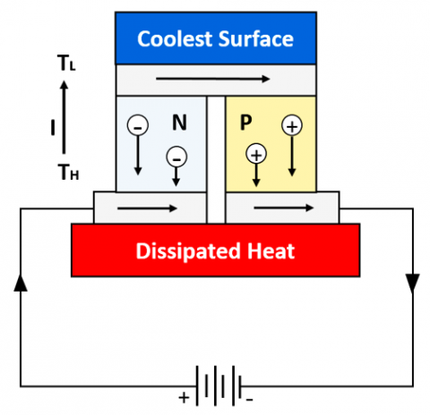
Thermoelectric refrigeration can be achieved by conducting a current, denoted as I, through one or more pairs of N- and P-type semiconductors interlinked with a high-conductivity metal as depicted in Figure 1 [4]. This process is characterized by the movement of electrons from a low energy level in the P-type material to a higher energy level in the N-type material via the connecting conductor, contingent on the electric current flowing from the N-type to the P-type semiconductor [5].
Consequently, a decrease in the temperature (TC) of the interconnecting conductor is observed, as it absorbs heat from the surrounding environment. The absorbed heat is then carried to the other end of the function via electron transport through semiconductors. As the electrons fall back to a lower energy level in the P-type material, the heat is released, leading to an increase in the temperature of TH [6]. The Peltier effect describes this process, with the Peltier coefficient, a function of the Seebeck coefficient of the semiconductor material and the absolute temperature, playing a central role. The Peltier coefficient is associated with a heating effect when the power supply polarity is switched and a cooling effect as the electric current moves from the N-type to the P-type semiconductor. The direction of the electric current thus determines the temperatures at both the hot and cold ends [7]. Recent advancements in thermoelectric materials suggest significant potential for enhancing their thermoelectric efficiency, marking a substantial stride towards novel application areas for thermoelectric modules [8]. For instance, a Modelica model of a Peltier water-to-water heat exchanger was developed for transient simulations [9]. This new model, which leverages TIL, an object-oriented Modelica library, has been utilized to simulate the transient behavior of a Peltier heat exchanger under an abrupt voltage reversion, with the numerical results cross-validated against the measurements from a prototype [9]. In their study, Liu and Zhang [10] outlined an experimental investigation of a solar thermoelectric air conditioner equipped with a hot water supply. The system demonstrated a high coefficient of performance (COP) when space cooling and water heating were coupled. Moreover, the internal constitution of thermoelectric components in an air conditioning system can be optimized, as discussed by Dongxu et al. [11] and Ruiz-Ortega et al. [12] for transient conditions. Thermoelectric modules have also been integrated into the ceiling for combining ventilation and airflow within a space [13]. Yilmazoglu [14] proposed a prototype heating, ventilation, and air conditioning (HVAC) system comprising a thermoelectric module with radiators installed in ventilation ducts. The system, tested using a single thermoelectric cooler (TEC), recorded flow and thermal conditions. Additionally, the internal structure of the thermoelectric module can be improved, possibly incorporating non-standard leg geometries [15-17]. By tuning the electric current and the number of modules, Attar and Lee [18] proposed a thermoelectric air conditioning system with air-to-air heat exchangers. Sun et al. [19] presented a novel radiant heating terminal connected to a TEC and evaluated its performance in real-world settings, which appeared to be faster and more effective than the conventional system. There has been substantial progress in the search for efficient thermoelectric materials [20, 21], and Pourkiaei et al. [22] provide a comprehensive review of thermoelectric modules and their applications. The heat transferred by a thermoelectric module needs to be extracted from the cooled area and expelled outside. Typically, this is achieved using fan-assisted radiators, possibly supplemented by a liquid medium that transfers heat from the TEC to the radiator. Only radiators with appropriate capacity can provide the required amount of heat transfer [23]. The heat-conducting medium may take the form of liquid water [24] or phase-change materials that utilize latent heat [25]. The U-shape or wrap-around heat pipe is ideal for an HVAC system requiring cooling with reheating [26]. In addition to the Peltier coefficient and the electric current flowing through the thermoelectric module, the heat absorbed at the cold end is influenced by two other factors. Firstly, due to the temperature difference between the hot and cold ends of semiconductors, heat is transmitted from the hot end to the cold end through the semiconducting materials. The thermal conductivity of the material and the temperature differential together determine the amount of heat transferred [27]. Secondly, when an electric current flows through semiconductors, a phenomenon known as Joule heat generation occurs due to electrical resistance R. This Joule heat, which is proportional to the square of the electric current, is produced equally at the cold and hot sides of the thermoelectric device and ultimately becomes the decisive factor [28]. The joule of heat finally takes over as the determining factor since it depends on electrical resistance and is proportional to the square of the electric current. The three distinct effects outlined above can be used to characterize heat absorption rate $Q^{\circ}$ at cold side of thermoelectric module.
$Q^{\circ}=\propto T_c I-\frac{1}{2} I^2 R-k\left(T_H-T_C\right)$ (1)
where,
α is the differential Seebeck coefficient sometimes referred to as αpn.
I electric current.
R is the electrical resistance of the thermoelements in series.
k the thermal conductance of the thermoelements in parallel.
TH and TC, hot side and cold side temperature respectively.
The coefficient of performance (COP), which is equal to the net heat absorbed at the cold junction divided by the electric power input [29], describes the energy efficiency of a thermoelectric device.
$C O P=\frac{Q^{\circ}}{P_{e l}}=\frac{\propto T_c I-\frac{1}{2} I^2 R-k\left(T_H-T_C\right)}{\propto \Delta T I+I^2 R}$ (2)
The ability of a semiconductor to cool is determined by See beck coefficient α, electrical resistivity ρ, and thermal conductivity k over operational temperature range between cold and hot junctions. Definition of electrical resistivity is:
$\rho=R \frac{A}{l}$ (3)
A is resistive material's cross-sectional area.
l is length.
Thermoelectric figure of merit Z is comprised of the three material qualities and is defined as:
$Z=\frac{\propto^2}{k \rho}$ (4)
Material scientists use the term "figure of merit" to describe the effectiveness of semiconductor materials in thermoelectric applications [30].
Figure 1. Thermoelectric device
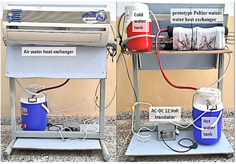
The manufacture of the main components of the device, the experimental procedure, and the measurement equipment are described. Many tests of the experimental rig were fabricated locally for testing the system's thermal performance and tested in the Najaf climate, where in the summer it is hot and dry and sometimes the temperature reaches 45 degrees Celsius. The experiments were tested with constant heat exchanger dimensions (Figure 2).
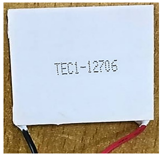
The thermoelectric device used in this experiment is Peltier type TEC1-12706 (12V-DC and 5.8 A) as shown in Figure 3. The device dimensions are (40×40×3) mm and the number of devices is 20.
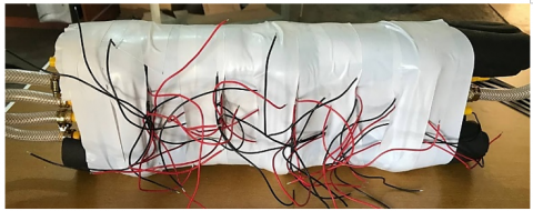
The Peltier devices were arranged and fixed on the aluminum rectangular tube (440×40×15) mm dimensions. Thermal paste is placed between the device and the tube to increase thermal conductivity and prevent thermal insulation by the air gap. The number of tubes is five and arranged as shown in Figure 4. An adhesive insulating tape was placed between the devices and between the pipes, and then a thermal insulator was placed for the group as a whole, see Figure 5. There are two lines in the tubes, one line to flow the cold water and the other line to flow hot water.
Figure 2. Experimental setup system
Figure 3. Thermoelectric device
Figure 4. Prototype Peltier water-water heat exchanger
Figure 5. Thermal insulation
The hot water tank (20 liters) is made of polyethylene; an axial fan dimension (25×25 cm) (220 Volt, 15 Watts, 1600 rpm) installed to the tank cover pulls the inside air. The air enters the tank cover through 40 holes with a diameter of 4 mm. The hot water comes from a heat exchanger by a rubber tube wound around the axial fan. Containing 20 circular holes with a diameter of 2 mm for water spray to increase water contact with the air and thus increase the evaporation rate. Which results in dragging the latent heat of evaporation from the hot water and rapidly decrease the water temperature [31]. Then cooled water return to the heat exchanger, indoor air conditional split unit (1200 Btu/h, 220 Volt, 40 Watt, 725 m3/h and 1250 rpm). The water in the unit is recycled by two small water pumps (220 Volt, 15 Watt and 2131 l/h) put in a storage tank for hot water and in a flash tank for cold water. A plastic tube joins the unit parts together 12.7 mm in diameter.
The Schematic diagram for the device and temperatures that must be measured for completing the device calculations are shown in Figure 6, and the names of the abbreviations were listed in Table 1:
Figure 6. Schematic diagram for the device
Table 1. The names of the abbreviations shown in Figure 6
|
S. No. |
Symbol |
Nomenclature |
|
1 |
Tcw out 1 |
Temperature of the cold water outlet 1 |
|
2 |
Tcw out 2 |
Temperature of the cold water outlet 2 |
|
3 |
Tcw in |
Temperature of the cold inlet water |
|
4 |
Thw in |
Temperature of the hot inlet water |
|
5 |
Thw out |
Temperature of the hot outlet water |
|
6 |
Ta in |
Temperature of the inlet air |
|
7 |
Ta out |
Temperature of the outlet air |
|
6 |
A-W HE |
Air-water heat exchanger |
|
7 |
PP W-W HE |
Prototype Peltier water-water heat exchanger |
|
8 |
CWP |
Cold water pump |
|
9 |
HWP |
Hot water pump |
|
10 |
ICWT |
Insulated cold water tank |
|
11 |
EhWT |
Evaporative hot water tank |
|
12 |
Efan |
Evaporative fan |
3.1 Measuring devices
A 32-channel, multi-channel temperature meter with an LCD display of type (AT4532) is employed. The temperature range was (-50℃) to (+1000℃) with accuracy (±1℃) and resolution (0.1). Seven thermocouples type K were used to measure the temperature distribution. Five thermocouples sensor (Flat Pin) was fixed by nylon cable ties on pipe surface (to measure the temperature on the main point of cycle) and insulated by insulation tape to avoid contact with another heat source from the system or ambient and then to save it insulating by duct tape. While the other two thermocouples (probe metal head) were fixed to measure inlet and outlet air temperature. To measure the cycle power conception, must be measure the electric current by Clamp meter.
All tests are following the same steps as follows:
1. Turn on the rig and wait for steady state (after 30 minutes).
2. Using the digital Multi-channel temperature meter to measure the five-minute temperatures.
3. Measurements were taken in the Al-Najaf climate [32].
4. The measurements started at 9:00 a.m. and were taken every five minutes.
The measured temperatures indicated in Figure 6 are the main factors that determine the functioning of the system. Ambient temperature it is direct affects the cooling of the hot tank water, which in turn affects the efficiency of the Peltier work, as it transfers heat from the hot side. The significant drop in temperature for the exit water temperature (Tcw out 2) from the Peltier water-water heat exchanger cold line shown in Figure 7. The air-water heat exchanger is not working until 30 minutes, after that, turn on the air-water heat exchanger until 65 minutes. Water temperature decreased to 14℃ and when turn on the heat exchanger, the temperature of the water increased as a result of heat gain from the air because the space is open and it did not putt the heat exchanger in a closed space or insulation box, the water temperature continued to rise to approximately the room air temperature.
Figure 7. Cold-water compared with air temperature
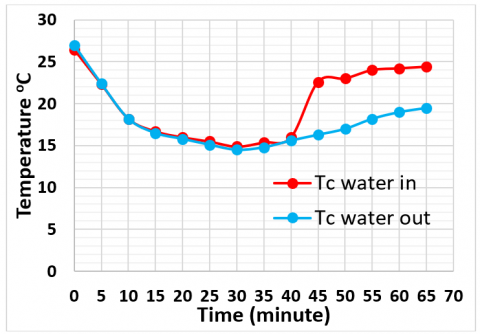
Figure 8 shows the temperature of the water inlet and outlet air-water heat exchangers. After turning on the heat exchanger at the 30th minute, it was noticed that the difference between the two curves increased due to the heat gain of the air. Moreover, after that, it noticed an increase in the temperature of the water entering because the space is not insulated, as mentioned previously.
Figure 8. Inlet and outlet cold-water temperature
Figure 9 shows the significant increase in the temperature for the exit water (Thw out) and inner water (Thw in) temperatures at the Peltier water-water heat exchanger hotline. The evaporative cooling for warm water is working, and keeping the water temperature at about 35.6℃ is a suitable temperature for cooling the device and preferably lower than that.
Figure 9. Hot-water temperature
Cold water can be used to cool the air once the system has stabilized and reached a temperature of 14℃ after 30 minutes. The air temperature difference between inside and outside is noticeable, especially between minutes 30 and 45. That is a good sign that the system is working, and the outcome will be better if a reliable power source is available and the heat exchanger is located in a closed and isolated area (Figure 10).
Figure 11 shows the refrigeration effect or cooling capacity of the system that was calculated from the heat loss quotient of the inlet and outlet air temperatures and from the air heat exchanger. According to the above, the refrigeration effect was high per minute 35 because the water temperature was low at this time, and then the refrigeration effect decreased with the increase in the temperature of the cooled water with time.
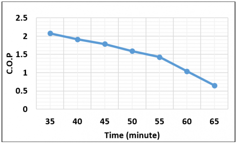
The system coefficient of performance depends on the refrigeration effect and the consumed power, as shown in Eq. (2). After measuring the temperatures and the consumed current, the coefficient of performance was calculated from the 35th minute, and the result was as shown in Figure 12, as it gradually decreases for the same reasons mentioned in the refrigeration effect.
Figure 10. Inlet and outlet air with water temperatures
Figure 11. Refrigeration effect
Figure 12. Coefficient of performance
It will be easier to comprehend how the system works and its limitations if the key elements affecting the performance of a thermoelectric multi-U shaped heat sink-based room air cooling system are discussed. The main elements to take into account are:
• The cooling capacity of the system is directly influenced by the temperature difference between the hot side of the thermoelectric modules, which faces the heat sink, and the cold side, which faces the room. More efficient heat transmission is made possible by greater temperature differences, which enhances cooling efficacy. The power input and system design may, however, be able to control the temperature differential because large temperature changes can result in thermal stress and decreased efficiency.
• There are numerous thermal resistances to take into account when discussing thermoelectric cooling: A- Thermoelectric Module Thermal Resistance: This resistance has an impact on how quickly heat is carried across the module. Better heat transmission and cooling performance are the result of lower thermal resistance in the module. B- Thermal Resistance of the Heat Sink: How effectively heat is removed from the hot side of the thermoelectric modules depends on the thermal resistance of the multi-U shaped heat sink. For better cooling, the heat sink should have a reduced thermal resistance.
• Significant elements affecting cooling performance include the heat transfer coefficients between the air and the hot and cold sides of the heat sink and the thermoelectric modules, respectively. Better cooling is made possible by higher heat transfer coefficients, which promote more effective heat dispersion.
• The thermoelectric modules' cooling capability is influenced by the quantity of electric current used to power them. Greater temperature differentials and greater cooling capability are typically associated with higher currents. However, this needs to be balanced with the system's thermal constraints and the necessary power input.
• Heat must be removed from the hot side of the thermoelectric modules, and this is accomplished in large part by the airflow through the multi-U-shaped heat sink and the effectiveness of the fans. The key to good cooling is adequate airflow and powerful fans.
• The efficiency of cooling is increased by properly thermally insulating the cold side of the thermoelectric modules, which reduces heat gain from the environment.
• The ambient temperature of the room or area being cooled influences the temperature difference between the cold and hot sides of the thermoelectric modules. Increased ambient temperatures may cause the system's cooling capacity to decline.
The present work studies the experimental investigation of using thermoelectric devices in air conditioning. According to the previous discussion of the obtained results, the following points can be concluded:
1. The results of cooling water with the thermoelectric device are acceptable.
2. The method of cooling water, whose temperature declined to 14℃, and subsequently chilling the room's air using the water-air heat exchanger between 20℃ and 24℃ proved successful, according to results.
3. To keep the water temperature of the hot water tank between 24℃ and 30℃, the evaporator airflow rate and the tank volume, like a cooling tower, must be increased.
4. The electrical power consumption of the thermoelectric and DC voltage are stable, as it can be operated on solar panels directly or any source of renewable energy.
5. It's crucial to remember that thermoelectric cooling systems are constrained by their very nature, such as their lesser efficiency when compared to more conventional vapor compression refrigeration systems. They are not suitable for large-scale cooling requirements but rather for localized cooling applications. Utilizing thermoelectric multi-U-shaped heat sink systems, better room air cooling can be achieved by comprehending and optimizing the aforementioned aspects.
In conclusion, the primitive practical attempt to manufacture a heat exchanger that works mainly on electrothermal and water is considered a successful attempt, and it can be developed by increasing the number of experimental attempts for several parts of it.
[1] Zorbas, K., Hatzikraniotis, E., Paraskevopoulos, K.M. (2007). Power and efficiency calculation and evaluation of material properties in thermoelectric power generators. MRS Online Proceedings Library, 1044: 915. https://doi.org/10.1557/PROC-1044-U09-15
[2] Bos, K., Huebener R., Tsuei C. (1998). Prospects for Peltier cooling of superconducting electronics. Cryogenics, 38(3): 325-328. https://doi.org/10.1016/S0011-2275(97)00171-9
[3] Winkler, J., Aute, V., Yang, B., Radermacher, R. (2006). Potential benefits of thermoelectric elements used with air-cooled heat exchangers. International Refrigeration and Air Conditioning Conference, West Lafayette, pp. R091.1-R091.8. http://docs.lib.purdue.edu/iracc.
[4] Richter, C. (2008). Proposal of new object-oriented model libraries for thermodynamic systems. Dissertation, TU Braunschweig. https://doi.org/10.24355/dbbs.084-200806100200-3
[5] Siddique, A.R.M., Bozorgi, M., Venkateshwar, K., Tasnim, S., Mahmud, S. (2023). Phase change material-enhanced solid-state thermoelectric cooling technology for food refrigeration and storage applications. Journal of Energy Storage, 60: 106569. https://doi.org/10.1016/j.est.2022.106569
[6] Mohiyodin, S.S., Ahmad, M., Abbas, M.Z., Hasan, K.S.J. (2017). Air-conditioner using Peltier modules. International Journal of Science & Engineering, 2: 2456-3293.
[7] Russel, M.D.K. (2011). A hybrid thermoelectric cooler thermal management system for electronic packaging. Master of Applied Science Thesis, McMaster University, Ontario, Canada. https://macsphere.mcmaster.ca/bitstream/11375/9891/1/fulltext.pdf.
[8] Nandini, K.K. (2013). Peltier based cabinet cooling system using heat pipe and liquid based heat sink. Department of Mechanical Engineering, NMAMIT, Nitte, India. https://doi.org/10.1049/cp.2013.2536
[9] Kravtcova, A. (2015). Development of cooling HVAC-type system based on thermoelectric effect. Degree Programme in Information Technology Thesis. https://core.ac.uk/download/pdf/38118574.pdf.
[10] Liu, Z.B., Zhang, L., Gong, G.C., Luo, Y.Q., Meng, F.F. (2015). Experimental study and performance analysis of a solar thermoelectric air conditioner with hot water supply. Energy and Buildings, 86(2015): 619-625. https://doi.org/10.1016/j.enbuild.2014.10.053
[11] Dongxu, J., Zhongbao, W., Pou, J., Mazzoni, S., Rajoo, S., Romagnoli, A. (2019). Geometry optimization of thermoelectric modules: simulation and experimental study. Energy Conversion and Management, 195: 236-243. https://dx.doi.org/10.1016/j.enconman.2019.05.003
[12] Ruiz-Ortega, P.E., Olivares-Robles, M.A., Badillo-Ruiz, C.A. (2012). Transient thermal behavior of a segmented thermoelectric cooler with variable cross-sectional areas. International Journal of Energy Research, 45(13): 19215-19225. https://doi.org/10.1002/er.7123
[13] Liu, Z.B., Zhang, L., Gong, G.C. (2014). Experimental evaluation of a solar thermoelectric cooled ceiling combined with displacement ventilation system. Energy Conversion and Management, 87: 559-565. https://doi.org/10.1016/j.enconman.2014.07.051
[14] Yilmazoglu, M.Z. (2016). Experimental and numerical investigation of a prototype thermoelectric heating and cooling unit. Energy and Buildings, 113: 51-60. https://doi.org/10.1016/j.enbuild.2015.12.046
[15] Shittu, S., Li G., Zhao, X., Ma, X. (2020). Review of thermoelectric geometry and structure optimization for performance enhancement. Applied Energy, 268: 115075. https://doi.org/10.1016/j.apenergy.2020.115075
[16] Fabián-Mijangos, A., Min, G., Alvarez-Quintana, J. (2017). Enhanced performance thermoelectric module having asymmetrical legs. Energy Conversion and Management, 148: 1372-1381. https://doi.org/10.1016/j.enconman.2017.06.087
[17] Wang, X., Qi, J., Deng, W., Li, G., Gao, X., He, L., Zhang, S. (2021). An optimized design approach concerning thermoelectric generators with frustum-shaped legs based on three-dimensional multiphysics model. Energy, 233: 120810. https://doi.org/10.1016/j.energy.2021.120810
[18] Attar, A., Lee, H.S. (2016). Designing and testing the optimum design of automotive air to air thermoelectric air conditioner (TEAC) system. Energy Conversion and Management, 112: 328-336. https://doi.org/10.1016/j.enconman.2016.01.029
[19] Sun, H., Lin, B., Lin, Z., Zhu, Y., Li, H., Wu, H. (2018). Research on a radiant heating terminal integrated with a thermoelectric unit and flat heat pipe. Energy and Buildings, 172: 209-220. https://doi.org/10.1016/j.enbuild.2018.04.054
[20] Conrad, K.J. (2015). A physics-based compact model for thermoelectric devices. Open Access Theses, 539. https://docs.lib.purdue.edu/open_access_theses/539.
[21] Eivari, H.A., Sohbatzadeh, Z., Mele, P., Assadi, M.H.N. (2021). Low thermal conductivity: fundamentals and theoretical aspects in thermoelectric applications. Materials Today Energy, 21: 100744. https://doi.org/10.1016/j.mtener.2021.100744
[22] Pourkiaei, S.M., Ahmadi, M.H., Sadeghzadeh, M., Moosavi, S., Pourfayaz, F., Chen, L., Pour Yazdi, M.A., Kumar, R. (2019). Thermoelectric cooler and thermoelectric generator devices: A review of present and potential applications, modeling and materials. Energy, 186: 115849. https://doi.org/10.1016/j.energy.2019.07.179
[23] Luo, D., Wang, R., Yu, W., Zhou, W. (2020). Performance optimization of a converging thermoelectric generator system via multiphysics simulations. Energy, 204: 117974. https://doi.org/10.1016/j.energy.2020.117974
[24] Junior, C., Richter, C., Tegethoff, W., Lemke, N., Koehler, J. (2008). Modeling and simulation of a thermoelectric heat exchanger using the object-oriented library TIL. Modelica. https://modelica.org/events/modelica2008/Proceedings/sessions/session4b3.pdf.
[25] Selvam, C., Manikandan, S., Krishna, N.V., Lamba, R., Kaushik, S.C., Mahian, O. (2020). Enhanced thermal performance of a thermoelectric generator with phase change materials. International Communications in Heat and Mass Transfer, 114: 104561. https://doi.org/10.1016/j.icheatmasstransfer.2020.104561
[26] Hakim, I.I., Sukarno, R., Putra, N. (2021). Utilization of U-shaped finned heat pipe heat exchanger in energy-efficient HVAC systems. Thermal Science and Engineering Progress, 25: 100984. https://doi.org/10.1016/j.tsep.2021.100984
[27] Martinez, A., Díaz de Garayo, S., Aranguren, P., Astrain, D. (2019). Assessing the reliability of current simulation of thermoelectric heat pumps for nearly zero energy buildings: Expected deviations and general guidelines. Energy Conversion and Management, 198: 111834. https://doi.org/10.1016/j.enconman.2019.111834
[28] Martinez, A., Díaz de Garayo, S., Aranguren, P., Araiz, M., Catalán, L. (2021). Simulation of thermoelectric heat pumps in nearly zero energy buildings: Why do all models seem to be right? Energy Conversion and Management, 235: 113992. https://doi.org/10.1016/j.enconman.2021.113992
[29] Multicomp, P. Thermoelectric Device Datasheet. MCTE1-19913L-S. http://uk.farnell.com/multicomp/mcte1-19913l-s/peltier-module-200w-50-x-50-x/dp/1639732, accessed on Apr. 12, 2023.
[30] Liu, X., Wang, Z. (2019). Printable thermoelectric materials and applications. Sec. Semiconducting Materials and Devices, 6. https://doi.org/10.3389/fmats.2019.00088
[31] Majdi, H.S., Ali, F.A.M.A., Habeeb, L.J. (2020). The rooms air conditioning by cooling the conventional water tank using hot summer air and solar energy. International Journal of Heat and Technology, 38(2): 472-478. https://doi.org/10.18280/ijht.380224
[32] Climate and Average Weather Year Round in Najaf - Iraq. https://weatherspark.com/y/103207/Average-Weather-in-Najaf-Iraq-Year-Round.