Alvaro Valencia*![]() | Sebastian Muñoz
| Sebastian Muñoz
© 2023 IIETA. This article is published by IIETA and is licensed under the CC BY 4.0 license (http://creativecommons.org/licenses/by/4.0/).
OPEN ACCESS
Compact heat exchangers equipped with flat tubes have traditionally been employed in automotive cooling systems. To augment thermal performance, louvered fins have been integrated on the air side. Over recent decades, the efficacy of longitudinal vortex generators (LVG) in heat exchangers has been rigorously investigated, leading to the proposal of innovative designs characterized by their aerodynamic properties. In this study, a novel LVG design sourced from extant literature was juxtaposed against the conventional louvered fins. The shear-stress transport (SST) k-ω model was utilized to depict the turbulence. When the turbulent flow and heat transfer properties were assessed, distinct variations were observed between multiple rows of LVG and the louvered fins. Enhanced thermal performance, with a value reaching 1.3, was noted for configurations incorporating five rows of LVG arrangements at a Reynolds number of 8000. In contrast, the thermal performance of louvered fins was observed to wane with increasing Reynolds numbers, recording a performance measure of merely 1.08 at the aforementioned Reynolds number.
compact heat exchanger, longitudinal vortex generator, louvered fins, shear-stress transport (SST) k-ω model, Reynolds number, thermal performance
Compact heat exchangers have historically been employed in scenarios where a gaseous and liquid medium interact. In these settings, the liquid is typically directed inside the tubes while the gas envelops the tubes' exterior. Due to the inherent poor heat conduction properties of gases, significant thermal resistance is often encountered. While circular tubes are commonplace, oval or flat tube variants have been adopted to mitigate pressure drop in the surrounding region. In efforts to enhance heat transfer on the gas side, fins are conventionally introduced to expand the transfer area. However, the effectiveness of plain fins is limited due to the growth of the boundary layer in tandem with flow direction. To counteract this limitation, louvered fins and wavy fins, designed to disrupt gas flow, have been integrated. Despite their efficacy, these methods have been associated with substantial pressure drops [1].
Achaichia and Cowell [2] detailed performance metrics of flat tube and louvered fins spanning Reynolds numbers from 120 to 8000, transitioning from laminar to turbulent flow. It was discerned that high Reynolds numbers favored a flow parallel to the louvers, whereas lower Reynolds numbers resulted in a flow dictated by the geometry of the louvers. At reduced Reynolds numbers, the shift from a flat plane to channel flow was noted, with laminar flow velocities hovering around 0.5 m/s.
In a separate investigation by Cuevas et al. [3], the thermo-hydraulic characterization of a louvered fin and flat tube in a heat exchanger was conducted. A discrepancy of 1.34 times between the identified heat transfer coefficient and those forecasted by literary correlations was reported on the air side.
Longitudinal vortex generators (LVG) have emerged as an alternative approach to amplify heat transfer rates on the gas side of heat exchangers and within channel flows. The introduction of LVG has been shown to disrupt thermal boundary layers, fostering the development of longitudinal vortices that persist over extended distances in flow channels [4]. Variations in LVG angle of attack and aspect ratio have been found to profoundly impact both heat transfer enhancement and associated pressure drop increases [5]. Although numerous studies have focused on plane channels with laminar flow or compact heat exchangers with plane fins and circular tubes, findings from laminar flow studies cannot be seamlessly transposed to turbulent flow contexts. It has been noted that thermal performance diminishes with rising Reynolds numbers [6].
Tiggelbeck et al. [7] embarked on an experimental comparison of delta wings, rectangular wings, delta winglet pairs, and rectangular winglet pairs for turbulent Reynolds numbers using liquid crystal thermography. Among the configurations, delta winglet pairs were identified as offering superior performance, boasting a heat transfer enhancement of 120% at Re=8000.
Fiebig et al. [8] undertook an experimental assessment of a compact heat exchanger model outfitted with both flat and circular staggered tubes using delta winglets as LVG. Evaluations for Reynolds numbers ranging between 600 and 3000 revealed that models employing flat tubes showcased enhanced heat transfer performance in comparison to those with circular tubes.
Meanwhile, Barquín and Valencia [9] executed a numerical analysis of varying fin and circular tube compact heat exchanger configurations equipped with longitudinal vortex generators. Optimal performance was achieved using two pairs of delta winglets in a common flow up–common flow down orientation. With this arrangement, a thermal performance factor 1.9 times greater than the baseline (absent LVG) was recorded at a Reynolds number of 1500.
Furthermore, within compact heat exchangers, the quantity of LVG positioned in the flow channel between the cylinders has been revealed to influence flow and heat transfer dynamics. Carpio and Valencia [10] examined a model incorporating flat tubes and plane fins, augmented with multiple delta winglets as LVG. Among the tested configurations, the iteration with 39 alternating LVGs yielded the most pronounced thermal performance, outperforming geometries devoid of delta winglets by a staggering 52%.
In a noteworthy contribution, Dogan and Abir İgci [11] unveiled a novel LVG design, subsequently undertaking an experimental assessment of its efficacy relative to delta winglet pairs within a rectangular channel under turbulent flow conditions. This innovative LVG, characterized by a curved delta wing profile, demonstrated a superior thermal performance, as defined in Eq. (12), in contrast to conventional delta winglet pairs [12].
In the context of compact heat exchangers equipped with staggered circular tube arrangements, thermal performance metrics (TEF) approximating 1.9 have been recorded using merely two LVG pairs for laminar flow, as per [9]. By leveraging flat tubes, a higher count of LVGs can be incorporated into the fin structure [10]. The turbulent flow and heat transfer, using different LVG as delta wing, delta winglet pair, inclined delta winglet pair and curved rectangular winglet pair was compared by Fuentes and Valencia [13]. Evidently, the relative performance of louvered fins hinges on the specific geometry of the compact heat exchanger and the prevailing flow regime.
The intent of the present analysis is to juxtapose the thermal performance metrics of a typical compact heat exchanger model, featuring flat tubes, against the industrial standard of louvered fins and rows of longitudinal vortex generators under turbulent flow conditions - a scenario frequently encountered in industrial applications. This geometry mirrors that of standard automotive radiators employed in combustion engine cooling systems.
2.1 Governing equations
In the analysis of the air side of the compact heat exchanger, the continuity, momentum, and energy equations serve as the primary governing equations. The assumption is made that the air is incompressible and its properties remain constant. Furthermore, the Reynolds-averaged Navier-Stokes (RANS) equations govern the airflow.
Continuity equation
$\frac{\partial u_i}{\partial x_i}=0$ (1)
Momentum equations
$\rho\left(\frac{\partial u_i}{\partial t}+u_j \frac{\partial u_i}{\partial x_j}\right)=-\frac{\partial P}{\partial x_i}+\mu\left(\frac{\partial^2 u_i}{\partial x_j x_i}\right)-\frac{\partial \overline{u_i^{\prime} u_j^{\prime}}}{\partial x_j}$ (2)
Energy equation
$\rho\, c_p\left(\frac{\partial T}{\partial t}+u_i \frac{\partial T}{\partial x_i}\right)=\frac{\partial}{\partial x_i}\left(k_{e f f} \frac{\partial T}{\partial x_i}\right)$ (3)
where, $u_i\left[\frac{\mathrm{m}}{\mathrm{s}}\right], \rho\left[\frac{\mathrm{kg}}{\mathrm{m}^3}\right], t[s], P[P a], \mu\left[\frac{N s}{\mathrm{~m}^2}\right], c_p\left[\frac{\mathrm{kJ}}{\mathrm{kgK}}\right], k_{e f f}\left[\frac{\mathrm{W}}{\mathrm{mK}}\right]$ represent velocity, density, time, pressure, dynamic viscosity, specific heat, and effective thermal conductivity, respectively.
For the turbulence modeling, the shear-stress transport (SST) model for turbulent kinetic energy, alongside the k-ω transport model for dissipation, is employed. Their equations are given as:
$\rho\left(\frac{\partial k}{\partial t}\right)+\rho \frac{\partial}{\partial x_i}\left(k u_i\right)=\frac{\partial}{\partial x_j}\left(\Gamma_k \frac{\partial k}{\partial x_j}\right)+G_k-Y_k$ (4)
$\rho\left(\frac{\partial \omega}{\partial t}\right)+\rho \frac{\partial}{\partial x_i}\left(\omega u_i\right)=\frac{\partial}{\partial x_j}\left(\Gamma_\omega \frac{\partial \omega}{\partial x_j}\right)+G_\omega-Y_\omega+D_\omega$ (5)
where, Gkand Gω denote the production of turbulent kinetic energy k and the dissipation ω, respectively. $\Gamma_k$ and $\Gamma_\omega$ are the effective diffusivities of k and ω, respectively, while Yk and Yω refer to the respective dissipations due to turbulence [14].
2.2 Geometry and computational domain
For this analysis, the compact heat exchanger's geometry, featuring louvered fins and flat tubes typically used in the automobile industry for radiators, was sourced from Cuevas et al. [3]. A single channel of the radiator was simulated.
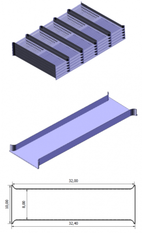
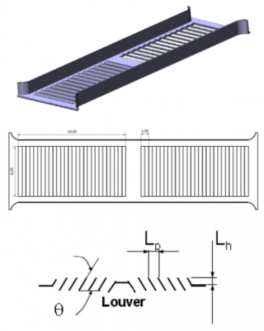
As depicted in Figure 1, a 3D perspective of the heat exchanger with louvered fins is provided alongside detailed insights into the louvered fins. Principal dimensions of both the base case (absent louvered fins) and the configuration with louvered fins are also presented in Figure 1. Key measurements include a fin separation of H=1.63 mm, a louvered angle of θ=20°, Lp=1 mm, and Lh=0.5 mm [3].
Figure 1. A 3D representation of the compact heat exchanger model equipped with louvered fins, and their primary dimensions in [mm]
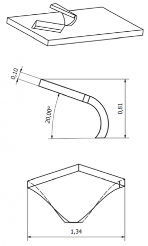
Figure 2. A 3D representation of the longitudinal vortex generator (LVG) accompanied by its main dimensions in [mm]
Figure 1 also illustrates the 3D views of models with plane fins (base case) and detailed aspects of the louvers. The vortex generator LVG's geometry under study was derived from the design proposed by Dogan and Abir İgci [11]. This particular LVG design demonstrated superior performance for turbulent Reynolds numbers below 25,000, as observed in a comparative study by Demirag et al. [12], exhibiting a thermal efficiency factor (TEF) of 1.34 at a Reynolds number of 5,000 within a plane channel. Notable for its aerodynamic blueprint, this design efficiently produces two longitudinal vortices, directing the oncoming flow towards the fin. The LVG's height was strategically designed to match half of the fin separation, quantified as h=0.5H=0.81 mm. Such a configuration, as reported by Carpio and Valencia [10], yielded impressive thermal performance results when paired with delta winglets. Figure 2 provides a comprehensive 3D view of the LVG in use, along with its primary dimensions in (mm).
Figure 3. Main dimensions concerning configurations with one to five rows of LVG
The TEF associated with an LVG is influenced by its geometry. While the classical delta winglet pair yields a relatively lower TEF, the introduction of this advanced LVG model, as indicated by the louvered fins in car radiators documented by Cuevas et al. [3], justifies its application due to its elevated TEF. The aim remains to juxtapose two distinct optimized solutions.
Figure 3 illustrates the quintet of varied configurations featuring the LVG, ranging from one to five rows. The relative transverse pitch separation for the LVG was also extracted from Dogan and Abir İgci [11]. The longitudinal spacing between each LVG row was determined based on the Computational Fluid Dynamics (CFD) results from prior cases. A focus on the local heat transfer distribution on the fin was maintained to pinpoint the subsequent LVG row's location, as it has been noted that local heat transfer tends to diminish following each LVG row, as can be observed in Figure 11.
2.3 Boundary conditions
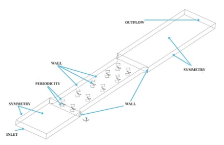
At the designated inlet boundary, both the velocity (U) and air temperature Tin were maintained constant. Symmetry conditions were applied to the lateral boundaries, while the exit region was subjected to an outflow boundary condition.
As illustrated in Figure 4, the boundary conditions and computational domain are clearly delineated. The air inlet temperature, Tin, was fixed at 293 K, while the flat cylinder region had its temperature set to Twall=363 K. The inlet velocity, U, ranged from 8.63 [m/s] to 34.52 m/s, corresponding to Reynolds numbers spanning from 2000 to 8000. The fins, constructed of aluminum, exhibited a thickness of 0.1 mm. In this region, the conduction model provided by the software ANSYS [14] was utilized.
The positions at which the inlet and outflow boundary conditions were implemented were chosen to be one and two lengths away from the compact heat exchanger model, respectively.
Figure 4. Boundary conditions depicted on the computational domain
2.4 Parameters and definitions
In the context of this study, several parameters have been defined to facilitate the analysis. These parameters, elucidated below, encompass essential concepts ranging from hydraulic diameters to the efficiency measurement of heat transfer.
The hydraulic diameter, DH, is derived from the minimum flow area, Amin, and its corresponding perimeter, P. This relationship is given by:
$D_H=\frac{4 A_{\min }}{P}$ (6)
Using DH, the Reynolds number, which relies on the inlet velocity, U, is described as:
$R e=\frac{\rho \cdot U \cdot D_H}{\mu}$ (7)
The log means temperature difference, crucial in heat transfer analysis, is defined by the equation:
$\Delta T_m=\frac{\left(T_w-T_{\text {in }}\right)-\left(T_w-T_{\text {out }}\right)}{\ln \left(\frac{\left(T_w-T_{\text {in }}\right)}{\left(T_w-T_{\text {out }}\right)}\right)}$ (8)
where, Tin represents the inlet air temperature, Tout is the outlet air temperature, and Tw is the average fin temperature.
In the assessment of the heat transfer coefficient, the equation below was employed:
$h=\frac{\dot{m} c_p\left(T_{\text {out }}-T_{\text {in }}\right)}{A_f \Delta T_m}$ (9)
where, $\dot{m}$ denotes the air mass flow rate in [kg/s], and Af is the wall area, specified in [m2].
The average Nusselt number, pivotal in heat transfer analysis, is expressed as:
$N u=\frac{h \cdot D_H}{k}$ (10)
To ascertain the friction factor, f, the pressure difference, $\Delta P$, between the inlet and outlet, in conjunction with the maximum velocity, Umax, were taken into account. This is defined by:
$f=\frac{2 \Delta P}{\rho \cdot U_{\max }^2} \cdot \frac{D_h}{L}$ (11)
The efficiency of heat transfer enhancement, upon introducing rows of LVG or louvered fins into the compact heat exchanger model, is quantified using the thermal performance metric (TEF) as delineated in Eq. (12) by Dogan and Abir İgci [11]. For a compact heat exchanger model with a flat fin and devoid of LVG, the TEF is designated a value of 0. Hence, a TEF exceeding one signifies an elevated heat transfer relative to the aforementioned model, assuming equivalent pumping power. It should be noted that this pumping power is proportional to the cube of the velocity.
$T E F=\frac{N u / N u_o}{\left(f / f_o\right)\,^{1 / 3}}$ (12)
The Nusselt number and the friction factor are influenced by the Reynolds number. A transition from laminar to turbulent flow within the channel is observed when Re exceeds 2000. Consequently, a turbulence model is employed to characterize the flow.
3.1 Numerical methodology
ANSYS FLUENT 2018 [14] was employed to execute numerical simulations of the distinct scenarios. Through the finite volume method, the Navier-Stokes equations were iteratively resolved utilizing the SIMPLEC algorithm. The SIMPLE algorithm enforces mass conservation by establishing a correlation between velocity and pressure corrections to ascertain the pressure field. An enhanced correction equation employed by SIMPLEC has been documented to hasten convergence in instances where pressure-velocity coupling proves critical for solution attainment [14].
Turbulence was characterized using the shear-stress transport (SST) k-ω model. Criteria were set with residuals falling below 10-3 for momentum equations and 10-6 for energy equations. Second-order discretization of the equations was implemented. The momentum residual was noted to be lesser than the energy residual, attributed to the momentum equation necessitating additional iterations for convergence, especially due to pressure and velocity coupling [14].
In the scenario featuring a singular row of LVG with a refined mesh and a Reynolds number of 4000, the final transient solution was juxtaposed against the steady method. Discrepancies observed in the Nusselt number and friction factor remained below 0.6%, leading to the selection of the steady method, given its advantage in reducing computational durations.
3.2 Mesh generation
The domain intended for meshing was segregated into three sub-domains. These corresponded to the inlet, heat exchanger, and exit regions delineated in the prior section.
Within the inlet and exit domains, elements of the hexahedral type were chosen, stemming from the uniformity of their geometric design. For all scenarios, a body sizing control with a dimension of 0.4 mm was employed in these regions.
In contrast, the heat exchanger domain witnessed the utilization of tetrahedral elements. The selection of this element type was motivated by its capability to adeptly represent the irregular geometrical intricacies when introducing LVG and louvered fins. Within this zone, a body sizing type control was implemented to ensure that the airflow domain comprised fine elements, capturing vortex formations effectively. Concurrently, in the vicinity of the fin surfaces, face-sizing was instigated due to the discernible gradients that characterize both heat transfer and momentum interactions with the airflow. The regions featuring LVG and louvers underwent an additional face sizing to accurately represent the elemental geometry, with the deployment of proximity and curvature options during the element construction phase.
Figure 5 elucidates the intricacies of the mesh, showcasing both hexahedral and tetrahedral element usage.
Figure 5. Illustration of the mesh incorporating hexahedral and tetrahedral elements
3.3 Validation test and mesh independence study
In turbulent flow with heat transfer within a pipe, correlations are determined as functions of the Reynolds number. The friction factor and Nusselt number in the channel flow were assessed in relation to the results obtained for pipe flow when considering the hydraulic diameter, as demonstrated in Eq. (7).
Eqs. (13) and (14) provide the correlations proposed by Petukvoh and Gnielinsky [15] for the friction factor and Nusselt number, respectively, associated with flow and heat transfer within a pipe:
$f=\frac{1}{(1.28 \log R e-1.64)^2}$ (13)
$N u=\frac{\left(\frac{f}{8}\right)(R e-1000) \operatorname{Pr}}{1+12.7 \sqrt{\frac{f}{8}}\left(\operatorname{Pr}^{\frac{2}{3}}-1\right)}$ (14)
Figure 6 displays a comparison between these correlations and a CFD simulation utilizing 1.5 million elements for the foundational scenario. This base case, featuring a contraction in the heat exchanger region as highlighted in Figure 5, diverges slightly from a plain channel model. Notably, for a Reynolds number of 4000, disparities of 3% in the friction factor and 13% in the Nusselt number were observed. The greatest discrepancies were recorded for a Reynolds number of 2000.
Figure 6. Variation of the friction factor and Nusselt number with the Reynolds number for the base case juxtaposed against standard correlations for planar channels
To ascertain mesh independence, simulations were conducted for the scenario with a single row of LVG at a Reynolds number of Re=4000 across four distinct mesh dimensions. The aggregate results for the mean Nusselt number and friction factor across these mesh dimensions are elucidated in Table 1 and depicted in Figure 7. Discrepancies between the 1.8 million-element mesh and the 1.5 million-element mesh were found to be minimal. Consequently, the 1.5 million-element mesh was selected for subsequent simulations. When comparing the coarsest mesh to the finest mesh, differences in both the Nusselt number and friction factor remained below 3%. The 1.5 million-element mesh yielded results virtually identical to its 1.8 million counterpart but was advantageous in terms of computational efficiency.
Table 1. Comparative data for Nusselt number and friction factor across different mesh dimensions for the scenario with a single LVG row at Re=4000
|
Mesh Size |
Nu |
f |
|
795200 |
23.233 |
0.07236 |
|
1227854 |
23.230 |
0.07160 |
|
1540625 |
22.913 |
0.07095 |
|
1837981 |
22.801 |
0.07071 |
Figure 7. Graphical representation of the variation in Nusselt number and friction factor with mesh size, specifically for the scenario with one LVG row at a Reynolds number of 4000
In Figure 8, the velocity magnitude coupled with turbulent intensity for the scenario of a single row of LVG, situated at a plane 3 mm downstream from the inlet for a Reynolds number of Re=4000, is depicted. The generation of two longitudinal vortices by the LVG is evident. Subsequent turbulence arises in the wake of the said geometrical features. The LVG’s impact on turbulent flow can be classified into two primary effects: the induction of longitudinal vortices and a localized surge in turbulence. The LVG is observed to induce a velocity oriented towards the walls, subsequently leading to a local boundary layer characterized by heightened gradients. A marked augmentation in turbulent intensity facilitates enhanced energy filtering in the transverse direction attributable to these vortices, leading to a localized elevation in heat transfer rates.
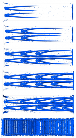
The Q criterion was employed to delve deeper into the longitudinal vortices generated by the varying rows of LVG and by the louvered fins. This criterion is delineated in Eq. (15):
$Q=\frac{1}{2}\left(u_{i, i}^2-u_{i, j} u_{j, i}\right)$ (15)
where, u represents the velocity component. In regions where the Q is identified as blue on the utilized scale, the flow is predominantly governed by the longitudinal vortices. The rationale behind the adoption of the Q criterion stems from its proficiency in capturing pivotal vortex structures within the flow domain, as affirmed by ANSYS [14]. Utilizing this particular criterion, the intensity of the longitudinal vortex can be comparatively assessed on a consistent scale.
Figure 8. Velocity magnitude [m/s] and turbulent intensity [%] for a single LVG row at the post-LVG plane located 3 mm downstream from the inlet at Reynolds number Re=4000
Figure 9. Visualization of the Q criterion for the scenarios of one to five rows of LVG and with louvered fins at Reynolds number Re=4000
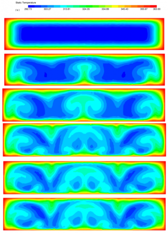
Figure 10. Temperature profiles for the base scenario and for configurations with one to five rows of LVG, assessed at a plane 18 [mm] downstream from the inlet at Reynolds number Re=4000
Figure 9 illuminates the Q criterion for scenarios encompassing one, two, three, four, and five rows of LVG as well as for the louvered fins setup. Evident coherent structures materialize in the wake of each LVG row. As the number of rows increases, more intricate structures emerge, underscoring the progressive augmentation of generated longitudinal vortices and their ensuing interactions. In the instance of the louvered fins, although vorticity is generated at each louver, such structures do not persist to the subsequent louver.
In Figure 10, temperature profiles at the compact heat exchanger's mid-plane are presented for both the base case and scenarios with one through five rows of LVG. When juxtaposing the temperature profile of the base case against those with LVG, a distinct thinning of the thermal boundary layer on both the lower and upper facets of the fin is discernible. Furthermore, a reduction in the blue zone, denoting a lower air temperature, was observed with the inclusion of LVG, signifying enhanced air heating.
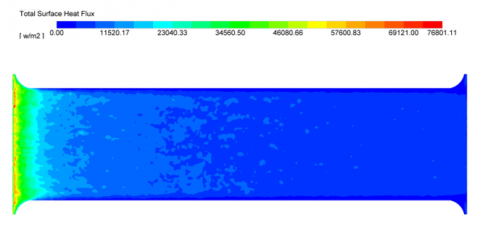
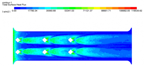
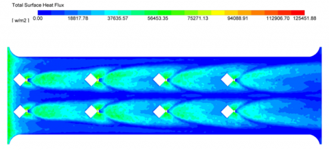
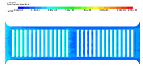
Figure 11 depicts the distribution of the local heat flux on the fin's bottom surface for the base case, scenarios with one through five rows of LVG, and for the louvered fin. The incorporation of each LVG row was found to elevate the local heat flux, attributed to the generated longitudinal vortices. However, a decrement in the heat flux intensity was observed downstream of the LVG (as evidenced in the single LVG row case). Subsequent rows of LVG were introduced at these positions, leading to the observation that with five rows of LVG, a majority of the fin area exhibited high local heat flux. Peak local heat flux values, approximating 53000 [W/m2], were discerned at the channel inlet and post the vortex generators. The role of the longitudinal vortices in influencing these heat flux values was evident.
Figure 11. Wall heat flux [W/m2] for base configuration, scenarios with one to five rows of LVG, and the louvered fin configuration at Reynolds number Re=4000
The implications of each LVG row on the fin become apparent in Figure 12, where the local Nusselt number, averaged over the transverse section, is portrayed for the five-row LVG scenario across six distinct Reynolds numbers. Each additional LVG row was observed to incrementally augment the Nusselt number, with subsequent rows further enhancing this metric. Therefore, in the compact heat exchanger model, post the entrance region, no decline in the local Nusselt number was observed with an increase in the longitudinal direction x.
Figure 12. Local Nusselt number across varied Reynolds numbers for the configuration with five rows of LVG
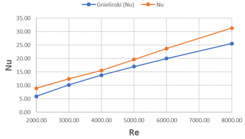
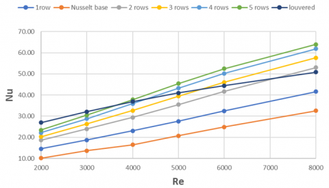
Figure 13. Average Nusselt number depicted for the base case, across five LVG configurations, and with louvered fins
In Figure 13, the average Nusselt number is plotted as a function of Reynolds number for the base case, across five different LVG configurations, and for louvered fins. While the slope of the curve for both the base case and the LVG configurations showed resemblance, a notably diminished slope was observed for the Nusselt number with louvered fins. It was inferred that while louvered fins predominantly induce turbulence within the flow, LVG simultaneously generates turbulence and longitudinal vortices. For Reynolds numbers exceeding 4000 and with the implementation of five rows of LVG, an augmented Nusselt number was discerned. Specifically, at a Reynolds number of 8000, configurations with 2, 3, 4, and 5 rows of LVG yielded Nusselt numbers surpassing those obtained using louvered fins.
Turning to Figure 14, the friction factor was delineated as a function of Reynolds number for the base case, five distinct LVG configurations, and for louvered fins. Mirroring observations from the Nusselt number, all LVG configurations and the base case exhibited congruent slopes. In contrast, a steeper negative slope was detected for louvered fins, attributed to their enhancement of turbulence within the model.
Figure 14. Friction factor rendered for the base case, across five LVG configurations, and for louvered fins
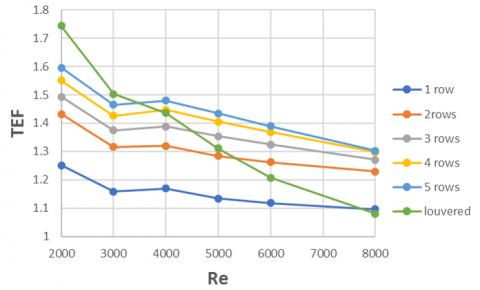
The Thermal Efficiency Factor (TEF) encapsulates the combined effects of heat transfer and pressure drop in the evaluated geometries, juxtaposed against the base case with plain fins and devoid of LVG. TEF is defined as the ratio between the heat transfer coefficients with and without LVG under equivalent pumping power conditions, leading to the power of one third for the friction factor in Eq. (12). A spike in TEF at a steady Reynolds number implies enhanced heat transfer at a constant pumping power. As presented in Figure 15 and enumerated in Table 2, a linear relationship between the Nusselt number and TEF was discerned, whereas the friction factor exhibited a cubical root dependency.
For Reynolds numbers falling below 4000, superior performance was ascribed to the louvered fins. However, a marked decrease in the TEF of louvered fins was witnessed with escalating Reynolds numbers. In scenarios involving elevated Reynolds numbers, the efficacy of the LVG configurations was significant. For instance, at a Reynolds number of 8000, and with the integration of five rows of LVG, a TEF of 1.3 was observed. This translates to a 30% increment compared to the base case, and a 22% enhancement relative to the louvered fins. Such findings suggest that LVGs foster efficient structures that facilitate the mixing of the primary flow and persist across an extensive region on the fin during turbulent flow conditions. A 30% TEF signifies a corresponding augmentation in heat transfer, all while maintaining the same pumping power within the compact heat exchanger.
Table 2. TEF values across evaluated geometries
|
Re |
One Row |
Two Rows |
Three Rows |
Four Rows |
Five Rows |
Louvered Fins |
|
2000 |
1.251 |
1.432 |
1.493 |
1.550 |
1.596 |
1.744 |
|
3000 |
1.158 |
1.316 |
1.375 |
1.426 |
1.465 |
1.503 |
|
4000 |
1.169 |
1.320 |
1.389 |
1.447 |
1.480 |
1.436 |
|
5000 |
1.135 |
1.284 |
1.354 |
1.405 |
1.435 |
1.311 |
|
6000 |
1.119 |
1.263 |
1.325 |
1.369 |
1.389 |
1.208 |
|
8000 |
1.097 |
1.230 |
1.271 |
1.297 |
1.303 |
1.080 |
Figure 15. TEF delineated across various LVG configurations and for louvered fins
When a TEF exceeding one is observed, it can be interpreted as a reduction in the heat exchange area on the air side, given that equivalent heat transfer is upheld at a consistent pumping power.
It was noted that the performance of louvered fins diminishes markedly as the inlet velocity escalates. Consequently, for elevated velocities (specifically when Re surpasses 4000), alternative methodologies such as the incorporation of LVGs are recommended. Beyond their application in the current context, LVGs have been suggested for potential utility in other domains to amplify passive heat transfer, especially within solar energy systems. Their efficacy, however, hinges on the appropriateness of their arrangement.
Several limitations were inherent to this investigation. The inlet velocity was maintained as constant, precluding any temporal fluctuations. Fin fouling, a potential real-world challenge, was not accounted for in the models. The analysis was restricted to a singular row of a flat tube, with implications associated with circular tubes remaining unexamined. Manufacturing costs, integral to the practical application of designs, were not evaluated for fins incorporating either LVGs or louvered fins. The use of longitudinal vortex generators can be explored in other fields as in photovoltaics systems cooling with air [16], in wind energy harvesting by aeroelastic excitation [17], for thermal energy storage systems [18], and for air pumps to enhance the flow in the mixing devices [19].
A numerical analysis was undertaken to contrast the fluid dynamics and heat transfer characteristics of a compact heat exchanger model equipped with flat tubes, incorporating either louvered fins or rows of LVGs. For two specific Reynolds numbers, superior TEF values were observed with the use of louvered fins. However, as the Reynolds number escalated, rows of LVGs demonstrated more promising performance metrics. Notably, at a Reynolds number of 8000, even a singular row of LVG manifested improved efficacy over its louvered fin counterpart.
The influence of longitudinal vortices on local wall heat transfer was found to wane with increased axial distance subsequent to the LVG positioning. Guided by this observation, successive rows of LVG were strategically placed, which led to an augmentation of local heat transfer across the fin.
By leveraging five rows of high-performance LVGs, a TEF value of 1.3 was achieved at a Reynolds number of 8000. It was discerned that the coherent longitudinal vortices generated by these LVGs surpassed the performance yielded by the turbulence intrinsic to louvered fins.
|
A |
surface area, m2 |
|
DH |
hydraulic diameter, m |
|
cp |
specific heat, J. kg-1. K-1 |
|
f |
friction factor |
|
h |
heat transfer coefficient, W.m-2.K-1 |
|
H |
model height, m |
|
k |
turbulent kinetic energy, m2s-2 |
|
L |
model length, m |
|
$\dot{m}$ |
mass flow, kg. s-1 |
|
Nu |
Nusselt number |
|
p |
pressure, Pa |
|
$\dot{q}$ |
heat flux, W.m-2 |
|
Re |
Reynolds number |
|
t |
time, s |
|
T |
temperature, K |
|
TEF |
thermal performance |
|
u |
velocity, m.s-1 |
|
v |
velocity, m.s-1 |
|
w |
velocity, m.s-1 |
|
x |
coordinate, m |
|
y |
coordinate, m |
|
Greek symbols |
|
|
ρ |
density, kg.m-3 |
|
μ |
dynamic viscosity, N.s.m-2 |
|
ω |
specific dissipation, m2.s-2 |
[1] Kays, W.M., London, A.L. (1998). Compact Heat Exchangers. 3rd Edition, McGraw-Hill, New York.
[2] Achaichia, A., Cowell, T.A. (1988). Heat transfer and pressure drop characteristics of flat tube and louvered plate fin surfaces. Experimental Thermal and Fluid Science, 1(2): 147-157. https://doi.org/10.1016/0894-1777(88)90032-5
[3] Cuevas, C., Makaire, D., Dardenne, L., Ngendakumana, P. (2011). Thermo-hydraulic characterization of a louvered fin and flat tube heat exchanger. Experimental Thermal and Fluid Science, 35(1): 154-164. https://doi.org/10.1016/j.expthermflusci.2010.08.015
[4] Biswas, G., Torii, K., Fujii, D., Nishino, K. (1996). Numerical and experimental determination of flow structure and heat transfer effects of longitudinal vortices in a channel flow. International Journal of Heat and Mass Transfer, 39(16): 3441-3451. https://doi.org/10.1016/0017-9310(95)00398-3
[5] Gentry, M.C., Jacobi, A.M. (2002). Heat transfer enhancement by delta-wing generated tip vortices in flat-plate and developing channel flows. Journal of Heat Transfer, 124(6): 1158-1168. https://doi.org/10.1115/1.1513578
[6] Skullong, S., Promthaisong, P., Promvonge, P., Thianpong, C., Pimsarn, M. (2018). Thermal performance in solar air heater with perforated-winglet-type vortex generator, Solar Energy, 170: 1101-1117. https://doi.org/10.1016/j.solener.2018.05.093
[7] Tiggelbeck, S., Mitra, N.K., Fiebig, M. (1994). Comparison of wing-type vortex generators for heat transfer enhancement in channel flows. Journal of Heat and Mass Transfer, 116(4): 880-885. https://doi.org/10.1115/1.2911462
[8] Fiebig, M., Valencia, A., Mitra, N.K. (1994). Local heat transfer and flow losses in fin and-tube heat exchangers with vortex generators: A comparison of round and flat tubes. Experimental Thermal and Fluid Science, 7(2): 130. https://doi.org/10.1016/0894-1777(93)90118-3
[9] Barquín, K., Valencia, A. (2021). Comparison of different fin and tube compact heat exchanger with longitudinal vortex generator in CFU-CFD configurations. International Journal of Heat and Technology, 39(5): 1523-1531. https://doi.org/10.18280/ijht.390514
[10] Carpio, J., Valencia, A. (2021). Heat transfer enhancement through longitudinal vortex generators in compact heat exchangers with flat tubes. International Communications in Heat and Mass Transfer, 120: 105035. https://doi.org/10.1016/j.icheatmasstransfer.2020.105035
[11] Dogan, M., Abir İgci, A. (2021). An experimental comparison of delta winglet and novel type vortex generators for heat transfer enhancement in a rectangular channel and flow visualization with stereoscopic PIV. International Journal of Heat and Mass Transfer, 164: 120592. https://doi.org/10.1016/j.ijheatmasstransfer.2020.120592
[12] Demirag, H.Z., Dogan, M., Igci, A.A. (2022). The numerical analysis of novel type conic vortex generator and comparison with known VGs for heat transfer enhancement. Heat Mass Transfer, 58: 735-762. https://doi.org/10.1007/s00231-021-03117-7
[13] Fuentes, H., Valencia, A. (2022). Comparison of turbulent flow and heat transfer in a rectangular channel with delta wing and winglet type longitudinal vortex generators. International Journal of Heat and Technology, 40(2): 366-374. https://doi.org/10.18280/ijht.400202
[14] ANSYS Documentation, 2020. www.ansys.com, accessed on July 6, 2021.
[15] Incropera, F.P., DeWitt, D.P. (1990). Fundamentals of Heat and Mass Transfer. Third Edition, John Wiley& Sons, New York.
[16] Al-Azawiey, S.S., Mohamed, M.M., Arifin, A.B. (2023). Effectiveness of PV/T passive natural air cooling by backside attached fins. International Journal of Energy Production and Management, 8(2): 55-62. https://doi.org/10.18280/ijepm.080201
[17] López-Arias, M., Nieto, F., Hernández, S. (2021). Experimental investigation on wind energy harvesting by aeroelastic excitation of a semi-circular cylinder with flat side parallel to the incoming flow. International Journal of Energy Production and Management, 6(1): 1-16. https://doi.org/10.2495/EQ-V6-N1-1-16
[18] Agarwal, A. (2023). Heat absorption performance enhancement of TES system using iron oxide/paraffin wax composite. Power Engineering and Engineering Thermophysics, 2(2): 73-85. https://doi.org/10.56578/peet020202
[19] Piancastelli, L. (2022). Continuous, high efficiency defrosting of air-to-air heat pumps. Power Engineering and Engineering Thermophysics, 1(1): 2-7. https://doi.org/10.56578/peet010102