Natiq Abbas Fadhil*![]() | Aamer Majeed Al-Dabagh
| Aamer Majeed Al-Dabagh![]() | Falah Fakhir Hatem
| Falah Fakhir Hatem![]()
© 2023 IIETA. This article is published by IIETA and is licensed under the CC BY 4.0 license (http://creativecommons.org/licenses/by/4.0/).
OPEN ACCESS
Enhancing heat transfer efficiency is crucial for the performance of heat exchangers, and the implementation of corrugated tubes has been shown to be an effective approach. In this study, a numerical investigation was conducted to analyze the impact of varying corrugation depths in rod baffles and two types of corrugated tubes (1 start and 3 start) on heat transfer and pressure drop characteristics. Water was used as the working fluid on the shell side of the heat exchanger, while a constant wall temperature was maintained on the tube side. Corrugation ratios (e/dh) of 0.1 and 0.13, pitch (p) of 10, 20, and 30 mm, and two types of rod baffle spacing (x/d) of 1.25 and 1.375 were considered. The analysis was performed in the turbulent flow regime with Reynolds numbers ranging from 4,000 to 24,000. Three-dimensional governing equations were solved using the standard k-ε model in ANSYS-Fluent 18.1 to examine the flow behavior within the corrugated tubes. The results indicated that a primary vortex was formed in the main flow due to the induced rotational flow along the helical path, as well as a secondary vortex behind the rib. These vortices disrupted the boundary layer and promoted flow mixing between layers. The average Nusselt number for corrugated tubes (pitch 10 mm) increased by 25% and 55% for corrugation depths of 0.1 and 0.13, respectively. However, the friction factor for corrugated tubes with (e/dh) = 0.1 and 0.13 was found to be higher than that of smooth tubes by 66%, 133%, and 130%. With the incorporation of both corrugated tubes and rod baffles, the thermal enhancement factor reached 1.9 for x/d = 1.25 and 1.97 for x/d = 1.375 at the same pumping power (50 mm). This study provides valuable insights into the effects of corrugated tubes and rod baffles on heat exchanger performance for various Reynolds numbers.
corrugated tube, rod baffle, friction factor, heat transfer enhancement, double pipe heat exchanger, CFD, ANSYS-Fluent
Today, there is a global issue with growing energy scarcity. Enhancing heat transmission is one way to increase energy effectiveness and conserve energy. There are several ways to improve heat transfer, and one effective method is to use tubes with intensified heat exchangers. In this particular field, many academics have made significant contributions.
The swirling turbulent gas-droplet flow in a sudden pipe expansion was studied using a mathematical model created by Pakhomov and Terekhov [1], who discovered that the swirl increased heat transfer. Accordingly, for the Petracci et al. [2] finned cylinder, the fins were positioned to enhance the average heat transmission. The average heat transfer on a finned cylinder cooled by a rectangular jet was examined in the study [2]. In their study of the heat transfer behavior in circular and internally longitudinal finned tubes under laminar flow circumstances, Ravi et al. [3] found that the Stefan number, fin thermal conductivity value, and fin height all had a substantial impact on the Nusselt number. In order to understand the regulating processes in fin tube flow and to examine the turbulent flow and heat transfer mechanisms in internally finned tubes, Kim et al.'s [4] numerical analysis created a series of comprehensive flow visualizations. They found that tall fin and microfin tubes have different controlling physics. In internally finned tubes with various viscosities, Shome [5] numerically investigated the developing mixed convection flow. They discovered that coring causes tubes with numerous fins or tall fins to perform poorly in terms of heat transfer and that the entrance region can produce significant improvements in heat transfer. Viscosity was also found to have a significant impact on estimations of the friction factor and Nusselt number. Dandotiya and Banker [6] designed a phase-change material-based heat exchanger with two new fin configurations, and the improved heat transfer was quantitatively assessed. Fin location was discovered to have a substantial impact on heat transfer. Li et al. [7], who discovered that this innovative insert was capable of entirely obstructing the core flow in circular tubes, computationally evaluated the heat transfer and friction factor of a circular tube with central slant rods. The ideal geometrical parameters were found after analyzing how insert geometry affected heat transmission and friction factor characteristics. Similar results were seen by Zhang et al. [8] when they examined a tube with multiple uniformly spaced twisted tapes. A unique increased heat transmission tube with segmented mesh-conical frustums was proposed by Cao et al. [9]. The performance of the insert geometric parameters and their impact on laminar thermal-hydraulic flow were numerically simulated in the study. The innovative inserts improved heat transfer with a small pressure drop, they discovered. There were also proposed connections between the friction factor and the Nusselt number. A feed-forward artificial neural network (ANN) was created by Shabanian et al. [10] to evaluate the thermal performance, friction factor, and Nusselt number in a tube with perforated twisted tape. Furthermore, a number of better empirical formulas were put out. In order to forecast the temperature and flow properties in a rectangular channel fitted with several twisted tape vortex generators, Beigzadeh et al. [11] used a hybrid model that included a back propagation network and a genetic algorithm. They discovered that the created neural networks performed better than Ebrahimi and Roohi [12], who analyzed the empirical correlations. Mini-twisted oval tubes' internal flow patterns and heat transmission were analyzed statistically, and links between the tube configurations and overall performance were reported. Tan et al. [13-15] did an examination of a twisted oval tube heat exchanger. The effectiveness of a twisted oval tube heat exchanger in transferring heat and lowering pressure on both the tube side and shell side was investigated through an experimental investigation. They observed that the twisted oval tube heat exchanger had better overall performance when compared to a rod baffle heat exchanger. The unique intensified heat exchanger tubes known as spirally corrugated tubes are frequently employed in heat exchangers. Academics from several fields have been interested in the performance of spirally corrugated tubes. In a 3D numerical analysis of the impact of spirally corrugated tubes on turbulent convection, Promthaisong et al. [16] found that the maximum heat rise occurred at a certain set of geometric parameters and operating circumstances. Lu et al. [17] did experimental research on the transition and turbulent convective heat transport of molten salt in a spirally curved tube. According to the study, increasing the depth of the corrugations can significantly improve heat conduction, and the flow of molten salt inside the tube had a greater Nusselt number than that of a smooth tube. Additionally adjusted were the correlations for the flow of molten salt in the spirally corrugated tube. In order to determine how to increase the rate of heat transfer in a spirally corrugated coiled-tube heat exchanger, Zachar [18] conducted a numerical study. In order to forecast the heat transfer coefficients and friction factors for the situation of a fully developed turbulent flow in a single-start spirally corrugated tube coupled with a twisted tape insert, Zimparov [19, 20] suggested a straightforward mathematical model. The multi-start spirally corrugated tube is the subject of several studies. Liu et al. [21] performed numerical research on the flow characteristics and shell-side heat transfer of rod-baffle heat exchangers with spirally corrugated tubes. They provided four models for the investigation: one-start, two-start, three-start, and four-start spirally corrugated tubes in RBHXsSCT (rod-baffle heat exchangers with spirally corrugated tubes). The results showed that, compared to RBHX, heat transfer quantities were larger and pressure drops were lower when Reynolds numbers were between 6,000 and 18,000. (Rod baffle heat exchangers with plain tubes). When the three-start spirally corrugated tube is used to boost heat transfer at low Reynolds numbers, it can significantly increase heat transfer with only a little increase in friction factor, according to research by Kareem et al. [22]. After conducting an experiment with four-start spirally corrugated tubes that concentrated on the non-symmetric nature of the corrugation angles along the longitudinal direction, Chen et al. [23] found that it was possible to modify the properties of heat transfer and friction by altering the internal non-symmetric wavy shapes of the tubes. The friction factor and heat transfer rate can both be increased by the five-start spirally corrugated tube, according to Promthaisong et al. [24], who numerically analyzed the turbulent airflow in the tube with different spiral pitch configurations. Numerically, rod baffles with different corrugation depths and corrugated tubes for two types (1 start and 3 start) have been studied in this work. After being heated at the wall, water is used as the working fluid on the heat exchanger's shell side, where a constant wall temperature is achieved on the tube side. There are two types (x/d) of 1.25 and 1.375, corrugation ratios (e/dh) of 0.1 and 0.13, and pitches (p) of 10, 20, and 30 mm. The investigation covered the turbulent Reynolds number range of 4000 to 24,000. As it is known, the grooves work to improve the heat transfer from the inside and from the outside, where this work was done on the external improvement. In addition to that, it was used a rod baffle and not the usual segmental to obtain a high-pressure drop from the side of the shell, where the rod also works to fix the pipes with each other.
2.1 Governing equations
The mathematical equations that have been applied in our study are (continuity, momentum, and energy equations) by using CFD software.
Continuity equation:
$\nabla \cdot(\rho u)=0$ (1)
Momentum equation:
$\frac{\partial}{\partial t}(\rho \vec{v})+\nabla \cdot(\rho \vec{v} \vec{v})=-\nabla P+\nabla \cdot(\vec{\tau})+\rho \vec{g}+\vec{F}$ (2)
Energy equation:
$\frac{\partial}{\partial t}(\rho E)+\nabla(\vec{v}(\rho E+p))=\nabla\left(K_{e f f} \nabla T-\sum_j h_j \vec{J}_i\left(\overline{\bar{\tau}}_{e f f} v\right)\right)+S_h$ (3)
2.2 Geometrical model
Figure 1. 1-Star groove tube with rod baffle
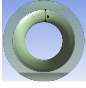
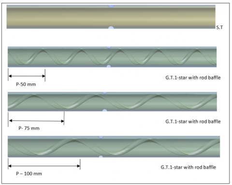
Heat exchanger thermal performance can be improved more effectively by using corrugated tube (1 start) and shell. As shown in Figure 1, the pipe is simulated with various corrugation configurations based on the CFD approach at various Re ranges from 4000 to 24000. The pipe has a 1000 mm length, a 16 mm diameter, and shell diameters of 20 and 22 mm. Under various working conditions, the varying pitches of this corrugation characteristic, including the corrugated ratio, are 0.1 and 0.13 mm. Three different pipelines are examined. Each pipe has varied corrugation configurations but the same pipe length and diameter characteristic parameters, as shown in Figure 2.
Figure 2. Boundary condition and dimension for 3-Star groove tube with rod baffle
2.3 Mesh and boundary conditions
The commercial program ANSYS-Fluent is used in this article to numerically simulate the shell side of a 1-start spirally corrugated tube (V.18.1). Water has the following physical properties that make it suitable for use as a heat transfer medium: The temperature is 300 K, the density is 998.2 kg/m3, the specific heat is 4,182 J/kg K, and the thermal conductivity is 0.6 W/m K. The inlet boundary condition is a velocity inlet. A pressure outlet boundary condition is stated, and the pressure is 0 Pa. The spirally corrugated tube wall is 373 K in temperature, and no-slip wall conditions are used on all walls. The material chosen for both walls is copper. Copper is often chosen as a material for walls due to several beneficial properties it possesses: Durability: Copper is highly durable and resistant to corrosion, making it a suitable choice for long-lasting structures. Malleability: Copper is a highly malleable metal, meaning it can be easily shaped and formed into various designs and patterns. Thermal Conductivity: Copper is an excellent conductor of heat. Copper walls can help in distributing heat evenly and minimizing energy losses. Sustainability: Copper is a recyclable material, and its recycling process requires significantly less energy compared to its extraction and production. Heat transfer and single-phase flow are assumed in the model. The Reynolds number is between 4,000 and 20,000. Due to the complexity of the shell-side heat transfer of the (1 and 3 start) spirally corrugated tube, simulations are conducted using the standard k-e turbulence model in conjunction with the wall function approach. The calculation processes assume steady 3D flow, and pressure and velocity are coupled using the SIMPLE algorithm's pressure implicit solver. A second-order upwind approach is used to treat the energy equations, turbulent dissipation rate, turbulent kinetic energy, and momentum equations. The choice of the standard k-epsilon turbulence model and the application of the wall function approach in the simulations can significantly impact the accuracy of the results, particularly in the context of corrugated tubes. Standard k-epsilon Turbulence Model: The standard k-epsilon turbulence model is one of the most widely used turbulence models in CFD simulations. It is a two-equation model that solves for two turbulent variables: kinetic energy (k) and its dissipation rate (epsilon). This model is preferred for many engineering applications due to its balance between accuracy and computational efficiency. However, it does have limitations, such as difficulties in predicting complex turbulent flows, boundary layer separation, and flows with strong streamline curvature.
In the context of corrugated tubes, the standard k-epsilon model can provide reasonable results when the flow remains within the model's validity range. However, if the flow exhibits highly complex turbulence characteristics or strong secondary flows induced by the corrugations, a more advanced turbulence model or a combination of models may be necessary. Wall Function Approach: The wall function approach is commonly employed to model the near-wall region in CFD simulations. In this approach, the computational grid is placed away from the physical wall, and near-wall effects are accounted for through empirically derived wall functions. These wall functions provide estimates of velocity and turbulent quantities based on the flow properties in the adjacent cells. The use of wall functions allows for coarser mesh resolution near the wall, reducing computational costs. Applying the wall function approach involves selecting appropriate wall functions, specifying the wall roughness, and determining the near-wall treatment. It is crucial to ensure that the wall functions are appropriate for the specific flow conditions and geometry, as they are based on certain assumptions and have limitations. In cases where the flow exhibits strong adverse pressure gradients or significant changes in wall properties, a more refined mesh or alternative modeling approaches may be required. The selection of turbulence models and the implementation of the wall function approach depend on the specific research objectives, available computational resources, and the desired balance between accuracy and computational efficiency.
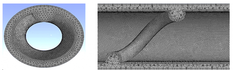
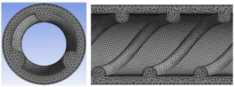
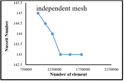
The creation of mesh domains is a crucial step in numerical calculations that influences both the speed and precision of the output. The computer simulation shown in Figures 3 and 4 employs a tetrahedral mesh structure. The near-wall grid is sufficiently fine to capture the temperature and velocity gradients. Figures 5 and 6 show the mesh independence for different cell counts. For Nusselt number and friction factor, respectively, 0.9 million, 1 million, 1.2 million, 1.3 million, 1.5 million, and 1.7 million (grooved tube three star-pitch 50 mm) cells are chosen for study because they produce more precise results than other scenarios. Table 1 shows the dimensions of the tested tubes for the solution geometry and boundary conditions. The number of nodes in a mesh and how the mesh is refined in areas of high flow gradients are crucial considerations in numerical simulations and computational fluid dynamics (CFD) analysis. Mesh refinement plays a vital role in achieving accurate and reliable results. Here's some aspects: Mesh Nodes: In numerical simulations, the mesh is divided into small elements or cells, and nodes are placed at the vertices of these cells. The number of nodes in the mesh determines the overall resolution and accuracy of the simulation. Generally, a higher number of nodes leads to a more detailed representation of the flow field but increases computational costs. Mesh Refinement: Mesh refinement involves increasing the number of nodes or decreasing the size of the elements in specific regions of interest. Areas with high flow gradients, such as near boundaries or in regions of flow separation, often require finer mesh resolution to capture the flow behavior accurately. This is because flow gradients can change rapidly in these regions, and a coarser mesh may not provide sufficient detail to capture the physics of the flow accurately. Adaptive Mesh Refinement: Adaptive mesh refinement is a technique that dynamically adjusts the mesh resolution based on the flow characteristics. This approach involves initially using a relatively coarse mesh and then refining it selectively in areas where it is needed. Various criteria can be used to determine the regions that require refinement, such as gradients in velocity, pressure, or other flow parameters. Adaptive mesh refinement helps to allocate computational resources more efficiently and focus them where they are most needed. Mesh Quality: Apart from node count and refinement, the overall quality of the mesh is crucial for accurate simulations. The mesh should exhibit good element shape, aspect ratio, and smoothness. Poor mesh quality, such as distorted elements or skewed angles, can lead to numerical instabilities, convergence issues, and inaccurate results. It's important to strike a balance between mesh resolution and computational resources. Extremely high-resolution meshes may lead to excessive computational costs, while excessively coarse meshes may compromise the accuracy of the simulation. Mesh quality, proper boundary conditions, and appropriate numerical schemes are also essential factors to consider for reliable CFD simulations.
Figure 3. Mesh for grooved tube 1-star
Figure 4. Mesh for grooved tube 1-star
Table 1. The dimensions of tested tubes of the solution geometry and boundary conditions
|
Definition |
Symbol |
Magnitude |
|
Diameter of the tube |
$\mathrm{d}_{\mathrm{t}}$ |
16 mm |
|
Diameter of the shell |
$\mathrm{d}_{\mathrm{sh}}$ |
20 and 22 mm |
|
Hydraulic Diameter |
$\mathrm{D}_{\mathrm{h}}$ |
4×area/wetted perimeter |
|
Rod baffle Diameter |
D |
4 mm |
|
Length |
L |
1000 mm |
|
Corrugation ratio |
e/dh |
0.1 and 0.13 |
|
Corrugation pitch |
P |
10, 20 and 30 mm |
|
Constant wall temperature |
$\mathrm{T}_{\mathrm{w}}$ |
373 K |
|
Inlet Temperature |
$\mathrm{T}_{\mathrm{in}}$ |
293 K |
|
Inlet Velocity |
U |
Calculated depends on Reynolds number |
|
Pressure Outlet |
- |
0 Pa |
Figure 5. Mesh independent for Nusselt number
Figure 6. Mesh independent for frication factor
2.4 Data reduction for numerical
This section considers a smooth tube that has a diameter of 20 mm and a length of 500 mm. The smooth tube's internal fluid flow is numerically simulated under the identical conditions as above. The bulk fluid temperature is:
$T_b=\frac{T_{\text {in }}+T_{\text {out }}}{2}$ (4)
To confirm the accuracy of the numerical procedure, empirical formulas [25] are utilized. The results resulting from the empirical formulas are compared to the Nusselt number Nu and the flow resistance coefficient f, respectively, acquired from the numerical simulation. One can derive the simulated Nu:
$N u=\frac{h d}{k}$ (5)
where, h is the heat transfer coefficient, d is the smooth tube's diameter, and k is the heat transfer medium's thermal conductivity. It is possible to determine the simulated flow resistance coefficient as follows:
$f=\frac{2 d \Delta p}{\rho u^2 l}$ (6)
where, d is the smooth tube's diameter, p is the pressure difference between its inlet and outlet, u is its mean inlet velocity, and l is its length. The empirical value of the Nusselt number Nu is determined from [26]:
Since this is pertinent to the operation, comparing heat transfer coefficients at equivalent pumping power allows for a useful comparison between reverse and straight flows. At constant pumping power, the thermal enhancement coefficient is expressed as follows:
$T . E . F=\frac{\left(\frac{N u_{G . t}\, }{N u_s}\right)}{\left(\frac{f_{G . t}}{f_S}\right)}$ (7)
2.5 Validation
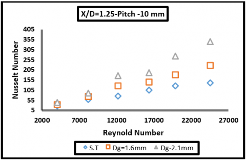
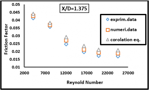
The present numerical method is validated by comparing the predicted numerical results with experimental data for water flow in an inward corrugated tube [27] and empirical correlation for gas flow in a smooth tube [Gnielinski [26] for Nusselt number and Filonenko [27] for friction factor, as shown in Figures 7 and 8.
Figure 7. Reynold number versus Nusselt number for smooth pipe and different depth grooved pipe with (x/d=1.25) and pitch=10 mm
Figure 8. Reynold number versus friction factor correlation with (x/d=1.375)
The choice to perform validation on a smooth tube rather than a corrugated tube can be influenced by several factors:
Simplification: Smooth tubes are often used in validation studies to simplify the experimental setup and analysis. Corrugated tubes introduce additional complexities due to their non-uniform geometry, which can make it more challenging to accurately measure and analyze flow characteristics or other parameters of interest. Baseline Comparison: By using a smooth tube as a baseline, researchers can establish a reference point for comparison. Corrugated tubes may exhibit different flow patterns and characteristics compared to smooth tubes, making it difficult to isolate and analyze the specific effects of other variables being tested. Specific Research Focus: The objective of the validation study is to examine the fundamental behavior of fluid flow or other phenomena within a tube. By using a smooth tube, researchers can isolate and investigate these fundamental aspects without the added complexity introduced by the corrugations. Cost and Practicality: Conducting experiments on corrugated tubes may require specialized equipment or custom fabrication, which can be more expensive or time-consuming. Smooth tubes are more readily available and easier to work with, making them a practical choice for initial validation studies. While validation on a smooth tube provides a baseline understanding, it's important to note that the behavior of fluids in corrugated tubes can differ significantly from that in smooth tubes. If the specific application involves corrugated tubes, further validation studies should be performed on the actual geometry to ensure accurate results and predictions for that particular configuration.
$N u=\frac{\left(\frac{f}{8}\right)(R e-1000) P r}{1.07+12.7\left(\frac{f}{8}\right)^{0.5}\left(\operatorname{Pr} r^{\frac{2}{3}}-1\right)}$ (8)
$f=\left(1.28 \log _{10} R e-1.64\right)^{-2}$ (9)
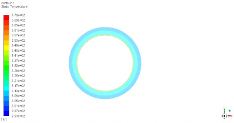
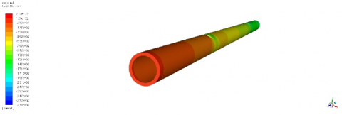
3.1 Pressure and temperature for smooth and grooved pipes
Figures 9-10 represent the static pressure and temperature contours for the smooth and grooved pipes. The static pressure and temperature of a fluid are two fundamental thermodynamic properties that are important in understanding the behavior of fluid flow through pipes. The static pressure is the pressure of a fluid at rest, while the temperature is a measure of the average kinetic energy of the molecules in the fluid. The static pressure and temperature contours for smooth and grooved pipes can be quite different due to differences in the fluid flow characteristics. For a smooth pipe, the flow is generally more laminar, meaning the fluid flows in smooth layers with little mixing between them. This results in a relatively uniform static pressure and temperature distribution across the pipe cross-section. The pressure drop in a smooth pipe is also relatively low due to the smooth surface of the pipe walls, which causes less resistance to the fluid flow.
Corrugated tubes are tubes with a helically shaped interior that creates a series of ridges or waves on the inner surface. These ridges can improve heat transfer rates and increase the turbulence of the fluid flow. The number of starts in a corrugated tube refers to the number of helical turns in the corrugation pattern. In general, a 3-start corrugated tube will provide higher heat transfer rates than a 1-start corrugated tube due to the increased turbulence created by the additional waves on the inner surface. This increased turbulence can also lead to a higher pressure drop across the tube, which may be a disadvantage in some applications where a low pressure drop is desirable.
Static pressure contours provide insights into the pressure distribution within the heat exchanger. In a heat exchanger, pressure drop is an important factor affecting the overall performance. Higher pressure drops can lead to increased pumping power requirements and reduced efficiency. By analyzing the static pressure contours, one can assess the flow behavior, identify regions of high and low pressure, and evaluate the impact on flow distribution and pressure losses across the heat exchanger. Temperature contours depict the thermal distribution within the heat exchanger. In a heat exchanger, the goal is to transfer heat from one fluid to another efficiently. Temperature contours allow for the visualization of heat transfer patterns, identifying regions of heat transfer enhancement or degradation. Uniform temperature distribution across the heat exchanger indicates effective heat transfer, while temperature gradients highlight areas where thermal performance may be compromised.
Figure 9. Static pressure contours for the smooth and grooved pipes
Figure 10. Static temperature contours for the smooth and grooved pipes
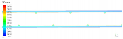
3.2 Static pressure with Reynolds number
Figures 11-13 represent the static pressure contours for grooved tubes and Re = 24000 with rod baffle, G.T. (3 stars), Re = 4000, smooth tube with baffle, d = 20 mm, and for Re (24000), smooth tube with baffle, d = 20 mm, respectively. In contrast, a grooved pipe can induce turbulence in the fluid flow due to the presence of the grooves. Turbulent flow is characterized by chaotic mixing of fluid layers, resulting in a more evenly distributed static pressure and temperature distribution across the pipe cross-section. However, the pressure drop in a grooved pipe is generally higher compared to a smooth pipe due to the increased fluid resistance caused by the grooves. Therefore, the static pressure and temperature contours for a smooth pipe will typically show a relatively uniform distribution, while those for a grooved pipe may show more fluctuations and turbulence effects. However, the exact contours will depend on the specific geometry of the pipe and the fluid properties. These properties can have significant impacts on the performance of fluid transport systems, and understanding the physical meaning behind them is important in designing and optimizing such systems.
The main difference between 1 start and 3 start corrugated tubes is the number of ridges or waves on the inner surface of the tube. A 1 start corrugated tube has one helical turn, which creates a single wave on the inner surface. A 3 start corrugated tube has three helical turns, which create three waves on the inner surface. This difference in the number of waves can affect the heat transfer and fluid flow characteristics of the tube. Additionally, the corrugation ratio, which is the ratio of the amplitude of the wave to the hydraulic diameter of the tube, can also affect the heat transfer and fluid flow characteristics of the tube. A higher corrugation ratio will create more turbulence and increase heat transfer rates, but it will also increase pressure drop. The specific application and design constraints will determine the optimal corrugation pattern and ratio for a given corrugated tube.
Figure 11. Static pressure contours for Re (24000) with rod baffle, G.T (3-star)
Figure 12. Static pressure contours for Re (4000), smooth tube with baffle, d=20 mm
Figure 13. Static pressure contours for Re (24000), smooth tube with baffle, d=20 mm
Pressure drop is a crucial parameter in heat exchanger performance evaluation. Grooved pipes, with their modified geometry, can influence the flow behavior and alter the pressure drop characteristics compared to smooth pipes. A direct comparison between grooved and smooth pipes would involve analyzing the pressure drop values for the different configurations. If the grooved pipes exhibit lower pressure drop compared to smooth pipes, it suggests that the flow resistance is reduced due to the presence of grooves. This can lead to lower energy consumption and pumping costs, improving the overall efficiency of the heat exchanger. Conversely, if the grooved pipes show higher pressure drop compared to smooth pipes, it indicates that the grooves introduce additional flow resistance. This may be attributed to increased turbulence or changes in flow direction caused by the grooved surface. Higher pressure drop can affect the system's performance by requiring increased pumping power.
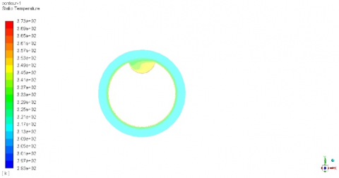
3.3 Temperature contour with rod baffle
Figures 14–17 represent the static temperature contours for Re=24000 with rod baffle, G.T. (3 stars), Re=4000 with baffle, G.T. (1 start), p = 30 mm, d = 1.6 mm, Re=4000, smooth tube with baffle, d = 20 mm, and Re=24000, smooth tube with baffle, d = 20 mm, respectively.
In turbulent flow, the fluid particles move chaotically, resulting in significant mixing and heat transfer between different regions of the fluid. As a result, the static temperature distribution in a turbulent flow system can be quite complex, with significant variations across the pipe cross-section.
The Reynolds number of 24000 indicates that the fluid flow is in the turbulent regime. This means that the fluid velocity is high enough that the flow becomes chaotic, with eddies and vortices forming in the fluid. The presence of a rod baffle can further enhance this turbulence, creating more eddies and mixing the fluid more thoroughly.
The 3-star geometry of the baffle may affect the static temperature contours in several ways. For example, the shape and orientation of the baffle may cause the fluid to swirl or create pressure gradients, which can impact the static temperature distribution in the pipe. Additionally, the spacing of the baffles and their effect on the flow regime can also play a role in determining the static temperature distribution. Overall, the static temperature contours for this system will be influenced by a variety of factors, including the Reynolds number, the presence of a rod baffle, and the specific geometry of the baffle. The differences between 1 start and 3 start corrugated tubes in terms of static pressure, temperature contour, and velocity vector depend on the specific geometry and operating conditions of the tube. In general, a 3 start corrugated tube will create more turbulence and generate higher heat transfer rates than a 1 start corrugated tube, which may result in differences in the static pressure and temperature contours and velocity vectors. The additional waves in a 3 start corrugated tube can create additional turbulence and vortices, which can cause a more complex and dynamic flow field compared to a 1 start corrugated tube. This can lead to differences in the static pressure and temperature contours, with a 3 start corrugated tube potentially having more fluctuations and variations in these parameters compared to a 1 start corrugated tube.
Figure 14. Static temperature contours for Re (24000) with rod baffle, G.T(3-star)
Figure 15. Static temperature contours for Re (4000) with baffle, G.T(1-start), p=30 mm, d=1.6 mm
Figure 16. Static temperature contours for Re (4000), smooth tube with baffle, d=20 mm
Figure 17. Static temperature contours for Re (24000), smooth tube with baffle, d=20 mm
By interpreting the static temperature contours in the context of a heat exchanger and considering the impact of different corrugation configurations, researchers can gain valuable insights into the heat exchanger's thermal performance, flow characteristics, and potential areas for design optimization. Different corrugation configurations in the heat exchanger can have a significant impact on static pressure and temperature contours. Corrugations can affect flow behavior, induce turbulence, enhance heat transfer, and alter pressure drop characteristics. Depending on the specific configurations tested, researchers can observe variations in pressure and temperature distributions, identifying regions of improved heat transfer or potential flow maldistribution. Comparative analysis of different corrugation configurations allows for assessing the influence of geometry on the heat exchanger's performance.
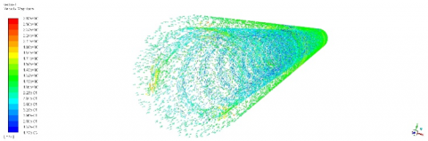
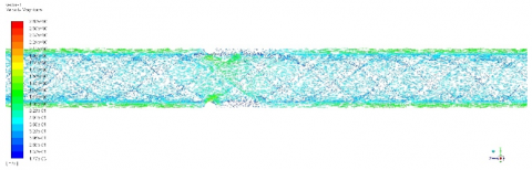
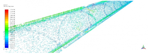
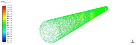
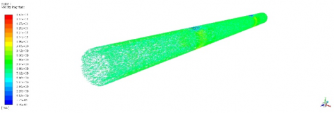
3.4 Velocity vector with different geometry
The study examines the effect of different corrugation configurations on fluid flow in pipes of various diameters, lengths, and shell diameters. The study is using a computational fluid dynamics (CFD) approach to simulate fluid flow in the pipes at various Reynolds numbers (4000 and 24000), as shown in Figures 18-26.
The varying pitches of the corrugation characteristics, including the corrugated ratio, are also being examined in the study. The corrugated ratio is a measure of the depth of the corrugations relative to the diameter of the pipe, and it can have a significant impact on the fluid flow behavior. The Reynolds number is between 4,000 and 20,000, indicating that the flow is in the turbulent regime. The study focuses on heat transfer and single-phase flow, with the aim of better understanding the heat transfer characteristics of the spirally corrugated tube under different flow conditions. The results of the simulation can be used to optimize the design of the tube for various applications where heat transfer is a critical factor. The simulation uses a rod baffle with a 3-star configuration, and it is unclear whether the spirally corrugated tube is present in this specific simulation. If it is, the velocity vector will be affected by the corrugations and the geometry of the tube.
In general, the velocity vector in a simulation with a rod baffle and spirally corrugated tube will vary depending on the specific design and operating conditions. The purpose of the simulation is to investigate the fluid flow and heat transfer characteristics under various conditions, and the results can be used to optimize the design for specific applications. The velocity vector is a representation of the direction and magnitude of the fluid flow at different locations in the simulation domain. It is calculated based on the fluid velocity field, which is solved by the numerical method used in the simulation. In the case of a simulation with a spirally corrugated tube and a rod baffle, the fluid flow will be affected by the presence of these features. The corrugations will create turbulence in the fluid, which can increase heat transfer rates but also lead to an increased pressure drop. The rod baffle will disrupt the flow and create eddies behind it, further affecting the velocity vector in the region downstream of the baffle. By visualizing the velocity vector in the simulation, we can gain insights into the behavior of the fluid in the tube and baffle assembly. We can see areas of high and low velocity, regions of turbulence, and the direction of the fluid flow. This information can be used to optimize the design of the tube and baffle for specific applications, such as heat exchangers or other heat transfer devices.
Figure 18. Velocity vector for Re (4000) with rod baffle G.T(3-star)
Figure 19. Velocity vector for Re (4000) with rod baffle G.T(3-star)
Figures 20. Velocity vector for Re (24000) with rod baffle G.T(3-star)
Figure 21. Velocity vector for Re (24000) with rod baffle G.T(3-star)
The velocity vector of the fluid flowing through a 3 start corrugated tube may be more complex and dynamic compared to a 1 start corrugated tube, due to the increased turbulence created by the additional waves. This can result in differences in the magnitude and direction of the velocity vector at different points in the tube. It is important to note that the specific differences in static pressure, temperature contour, and velocity vector between 1 start and 3 start corrugated tubes will depend on the specific geometry and operating conditions of the tube, including the corrugation ratio, Reynolds number, and other relevant parameters. These differences can be quantified through fluid dynamics simulations.
Figure 22. Velocity vector for Re (4000) with baffle, G.T(1-start), p=30 mm and d=1.6 mm
Figure 23. Velocity vector for Re (4000) smooth tube with baffle, d=20 mm
Figure 24. Velocity vector for Re (4000) smooth tube with baffle, d=20 mm
Figure 25. Velocity vector for Re (24000) smooth tube with baffle, d=20 mm
Figures 26. Velocity vector for Re (24000) smooth tube with baffle, d=20 mm
The study examines three different pipelines, each with varied corrugation configurations but the same length and diameter characteristics. This approach allows for a more controlled comparison of the effects of different corrugation configurations on fluid flow in pipes. Overall, the study aims to better understand the impact of corrugation configurations on fluid flow behavior in pipes under various working conditions. The results of the study can inform the design and optimization of corrugated pipes for various applications, including fluid transport and heat transfer. A simulation is being conducted to investigate the heat transfer characteristics of water flowing through a spirally corrugated tube made of copper. The simulation uses the standard k-epsilon turbulence model in conjunction with the wall function approach to model the complexity of the shell-side heat transfer. The simulation assumes steady 3D flow, and the pressure and velocity are coupled using the SIMPLE algorithm's pressure implicit solver. A second-order upwind approach is used to treat the energy equations, turbulent dissipation rate, turbulent kinetic energy, and momentum equations. The simulation uses a set of physical properties for water, including temperature, density, specific heat, and thermal conductivity. The inlet boundary condition is a velocity inlet, and a pressure outlet boundary condition is stated with a pressure of 0 Pa. The spirally corrugated tube wall is assumed to have a temperature of 373 K, and no-slip wall conditions are used on all walls. The material chosen for both walls is copper.
This article explores corrugated tubes for two types of rod baffles with numerically varying corrugation depths. Water is used as the working fluid on the heat exchanger's shell side after being heated at the wall. There are two varieties (x/d) of 1.25 and 1.13 corrugation ratios (e/dh) and pitches of 10, 20, and 30 mm. The turbulent Reynolds number range for the investigation was between 4000 and 24,000. ANSYS-Fluent 18.1 was used to solve classic k-e model three-dimensional governing equations, and the results showed that the rotating flow that was induced along the helical path led to the creation of a primary vortex in the main flow. The boundary layer can be broken up by these two vortices, which promote flow mixing between the flow layers and considerably enhance heat transfer.
Tube corrugations can disrupt flow patterns and result in thermal boundary layer cracking, so it is important to increase the temperature difference between the surfaces and surrounding flow temperatures to achieve this. Depth has a major impact on heat transmission, as boundary layers are thicker in smooth tubes with low Reynolds numbers. Internal flow in corrugated tubes is difficult due to the helical rib's drag forces, rotational flow, augmentation of frictional drag, and flow obstruction. Corrugated tubes have a helically formed interior covered with ridges or waves, which can speed up heat transfer and increase fluid flow turbulence. The quantity of starts in a corrugated tube denotes the quantity of helical turns in the pattern of corrugation. A 3 start corrugated tube will often offer higher heat transfer rates than a 1 start corrugated tube. However, the velocity vector of the fluid moving through a 3 start corrugated tube may be more complex and dynamic than it is in a 1 start corrugated tube, leading to variations in the velocity vector's amplitude and direction at various locations throughout the tube. Fluid dynamics simulations can be used to quantify these variations.
The static pressure and temperature contours provide insights into the performance of the heat exchanger. By analyzing the contour patterns, researchers can assess factors such as heat transfer effectiveness, thermal uniformity, pressure drop, and flow distribution. These parameters are critical for evaluating the overall efficiency, performance, and effectiveness of the heat exchanger design.
Heat transfer coefficients indicate the effectiveness of heat transfer within the heat exchanger. Comparing the heat transfer coefficients between grooved and smooth pipes can provide insights into the impact of grooved surfaces on heat transfer enhancement. If the grooved pipes exhibit higher heat transfer coefficients compared to smooth pipes, it suggests that the grooves promote better heat transfer. The presence of grooves can enhance the turbulence level, increase the heat transfer surface area, and improve the thermal mixing between the fluids. This results in more efficient heat transfer and potentially compact heat exchangers. Conversely, if the heat transfer coefficients are lower for grooved pipes compared to smooth pipes, it implies that the grooves may disrupt the flow and reduce heat transfer efficiency. The grooves could potentially hinder the proper fluid mixing, leading to reduced convective heat transfer performance. By directly comparing the pressure drop and heat transfer coefficients between grooved and smooth pipes, researchers can assess the impact of grooved surfaces on the heat exchanger's performance. These comparisons help identify the trade-offs between flow resistance and heat transfer enhancement, providing valuable insights for optimizing the design of grooved heat exchangers.
|
d |
Hydrolic diameter, mm. |
|
e |
Corrugation depth, mm. |
|
f |
Friction factor. |
|
k |
Thermal conductivity, W.m-1. K-1 |
|
L |
Length, mm |
|
Nu |
Local Nusselt number along the heat source |
|
P |
Pitch, mm |
|
µ |
Dynamic viscosity, kg. m-1.s-1 |
|
T |
Temperature, K. |
|
u |
Velocity, m/sec. |
|
Subscripts |
|
|
f |
fluid (pure water) |
|
h |
Hydrolic diameter |
|
in |
Inlet |
|
out |
Outlet |
[1] Pakhomov, M.A., Terekhov, V.I. (2017). Numerical modeling of turbulent flow structure and heat transfer in a droplet-laden swirling flow in a pipe with a sudden expansion. Numerical Heat Transfer, Part A: Applications, 71(7): 721-736. https://doi.org/10.1080/10407782.2017.1308740
[2] Petracci, I., Manni, L., Gori, F. (2016). Numerical simulation of the optimal spacing for a radial finned tube cooled by a rectangular jet. I–Average thermal results. International Journal of Thermal Sciences, 104: 54-67. https://doi.org/10.1016/j.ijthermalsci.2016.01.001
[3] Ravi, G., Alvarado, J.L., Marsh, C., Kessler, D.A. (2009). Laminar flow forced convection heat transfer behavior of a phase change material fluid in finned tubes. Numerical Heat Transfer, Part A: Applications, 55(8): 721-738. https://doi.org/10.1080/10407780902864672
[4] Kim, J.H., Jansen, K.E., Jensen, M.K. (2004). Analysis of heat transfer characteristics in internally finned tubes. Numerical Heat Transfer, Part A: Applications, 46(1): 1-21. https://doi.org/10.1080/10407780490454296
[5] Shome, B. (1998). Mixed convection laminar flow and heat transfer of liquids in horizontal internally finned tubes. Numerical Heat Transfer, Part A Applications, 33(1): 65-83. https://doi.org/10.1080/10407789808913928
[6] Dandotiya, D., Banker, N.D. (2017). Numerical investigation of heat transfer enhancement in a multitube thermal energy storage heat exchanger using fins. Numerical Heat Transfer, Part A: Applications, 72(5): 389-400. https://doi.org/10.1080/10407782.2017.1376976
[7] Li, P., Liu, Z., Liu, W., Chen, G. (2015). Numerical study on heat transfer enhancement characteristics of tube inserted with centrally hollow narrow twisted tapes. International Journal of Heat and Mass Transfer, 88: 481-491. https://doi.org/10.1016/j.ijheatmasstransfer.2015.04.103
[8] Zhang, X., Liu, Z., Liu, W. (2012). Numerical studies on heat transfer and flow characteristics for laminar flow in a tube with multiple regularly spaced twisted tapes. International Journal of Thermal Sciences, 58: 157-167. https://doi.org/10.1016/j.ijthermalsci.2012.02.025
[9] Cao, Z., Wu, Z., Luan, H., Sunden, B. (2017). Numerical study on heat transfer enhancement for laminar flow in a tube with mesh conical frustum inserts. Numerical Heat Transfer, Part A: Applications, 72(1): 21-39. https://doi.org/10.1080/10407782.2017.1353386
[10] Shabanian, S.R., Lashgari, S., Hatami, T. (2016). Application of intelligent methods for the prediction and optimization of thermal characteristics in a tube equipped with perforated twisted tape. Numerical Heat Transfer, Part A: Applications, 70(1), 30-47. https://doi.org/10.1080/10407782.2016.1139982
[11] Beigzadeh, R., Rahimi, M., Parvizi, M., Eiamsa-ard, S. (2014). Application of ANN and GA for the prediction and optimization of thermal and flow characteristics in a rectangular channel fitted with twisted tape vortex generators. Numerical Heat Transfer, Part A: Applications, 65(2): 186-199. https://doi.org/10.1080/10407782.2013.826010
[12] Ebrahimi, A., Roohi, E. (2015). Numerical study of flow patterns and heat transfer in mini twisted oval tubes. International Journal of Modern Physics C, 26(12): 1550140. https://doi.org/10.1142/S0129183115501405
[13] Tan, X.H., Zhu, D.S., Zhou, G.Y., Zeng, L.D. (2013). Heat transfer and pressure drop performance of twisted oval tube heat exchanger. Applied thermal engineering, 50(1): 374-383. https://doi.org/10.1016/j.applthermaleng.2012.06.037
[14] Tan, X.H., Zhu, D.S., Zhou, G.Y., Zeng, L.D. (2012). Experimental and numerical study of convective heat transfer and fluid flow in twisted oval tubes. International Journal of Heat and Mass Transfer, 55(17-18): 4701-4710. https://doi.org/10.1016/j.ijheatmasstransfer.2012.04.030
[15] Tan, X.H., Zhu, D.S., Zhou, G.Y., Yang, L. (2013). 3D numerical simulation on the shell side heat transfer and pressure drop performances of twisted oval tube heat exchanger. International Journal of Heat and Mass Transfer, 65: 244-253. https://doi.org/10.1016/j.ijheatmasstransfer.2013.06.011
[16] Promthaisong, P., Jedsadaratanachai, W., Eiamsa-Ard, S. (2016). 3D Numerical study on the flow topology and heat transfer characteristics of turbulent forced convection in spirally corrugated tube. Numerical Heat Transfer, Part A: Applications, 69(6): 607-629. https://doi.org/10.1080/10407782.2015.1069670
[17] Lu, J., Sheng, X., Ding, J., Yang, J. (2013). Transition and turbulent convective heat transfer of molten salt in spirally grooved tube. Experimental Thermal and Fluid Science, 47: 180-185. https://doi.org/10.1016/j.expthermflusci.2013.01.014
[18] Zachár, A. (2010). Analysis of coiled-tube heat exchangers to improve heat transfer rate with spirally corrugated wall. International Journal of Heat and Mass Transfer, 53(19-20): 3928-3939. https://doi.org/10.1016/j.ijheatmasstransfer.2010.05.011
[19] Zimparov, V. (2004). Prediction of friction factors and heat transfer coefficients for turbulent flow in corrugated tubes combined with twisted tape inserts. Part 1: Friction factors. International Journal of Heat and Mass Transfer, 47(3): 589-599. https://doi.org/10.1016/j.ijheatmasstransfer.2003.08.003
[20] Zimparov, V. (2004). Prediction of friction factors and heat transfer coefficients for turbulent flow in corrugated tubes combined with twisted tape inserts. Part 2: heat transfer coefficients. International Journal of Heat and Mass Transfer, 47(2): 385-393. https://doi.org/10.1016/j.ijheatmasstransfer.2003.08.004
[21] Liu, J.J., Liu, Z.C., Liu, W. (2015). 3D numerical study on shell side heat transfer and flow characteristics of rod-baffle heat exchangers with spirally corrugated tubes. International Journal of Thermal Sciences, 89: 34-42. https://doi.org/10.1016/j.ijthermalsci.2014.10.011
[22] Kareem, Z.S., Abdullah, S., Lazim, T.M., Jaafar, M.M., Wahid, A.F.A. (2015). Heat transfer enhancement in three-start spirally corrugated tube: Experimental and numerical study. Chemical Engineering Science, 134: 746-757. https://doi.org/10.1016/j.ces.2015.06.009
[23] Chen, X.D., Xu, X.Y., Nguang, S.K., Bergles, A.E. (2001). Characterization of the effect of corrugation angles on hydrodynamic and heat transfer performance of four-start spiral tubes. ASME Journal of Heat and Mass Transfer, 123(6): 1149-1158. https://doi.org/10.1115/1.1409261
[24] Promthaisong, P., Jedsadaratanachai, W., Chuwattanakul, V., Eiamsa-ard, S. (2017). Heat transfer and fluid flow behaviors in a five-start spiral corrugated tube. In AIP Conference Proceedings, 1879(1): 020005. https://doi.org/10.1063/1.5000461
[25] Munson, B.R., Young, D.F., Okishi, T.H., Huebsch, W.W. (2009). Fundamentals of Fluid Mechanics. 6th Ed. New York, NY, USA: John Wiley & Sons.
[26] Gnielinski, V. (1976). New equations for heat and mass transfer in turbulent pipe and channel flow. International chemical engineering, 16(2): 359-367.
[27] Filonenko, G. (1954). Hydraulic resistance in pipes. Teploenergetika, 1: 40-44.