Sarah R. Nashee![]()
© 2023 IIETA. This article is published by IIETA and is licensed under the CC BY 4.0 license (http://creativecommons.org/licenses/by/4.0/).
OPEN ACCESS
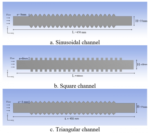
To support and improve the results of the intensive studies that performed on developing the thermal systems and enhancing their thermal performance, experiments were conducted on 2D-Corrugated channels (L=450 mm) with a number of geometric shapes of corrugation (sinusoidal, triangular and square) with fixed hight of amplitude of corrugation (8 mm) In addition, four corrugation angles (25°, 30°, 35°, 40°, 45°) the triangular corrugated channel. The study applies Reynold numbers range between 500 and 2500. The tests have been done theoretically by using FLUENT a comparison has been done among the results of heat transfer and friction factor of the corrugated channels and the smooth channel, A high enhancement in the overall performance was found specially in the triangular corrugated channel with raise in the value of pressure drop. In addition, the obtained results of Nusselt number and friction factor of five angles present that the greatest angle gives the highest values of Nusselt number and friction factor Acceptable agreement was gained when a compassion was conducted among the current results and previous studied.
corrugated channel, laminar flow, thermal performance
The growing consumption of the energy sources over the years the forces engineers and researchers to output more effective energy systems so that can be led to use effectively energy sources. the researchers conducted many studies to enhancing the rate of heat transfer with an agreeable pressure drop. That can be very helpful to make more compact heat exchangers which are employing in the systems of air-conditioning, nuclear reactor, heat exchangers, thermal power plants, chemical reactors and many thermal applications [1].
Experimental and numerical works have been based on thermal performance improvement; these experiments proved clearly that the corrugated passages of flow one of the effective ways to raise the heat transfer rate. The employing of corrugation leads to a notably complex flow manner which promotes more better momentum transfer and the recirculation of the flow that resulting enhancement in the rate of heat transfer [2]. There are a number of studies that have studied corrugated passages and their effect on the rate of heat transfer and improving the thermal performance of thermal systems Goldstein and Sparrow [3] were possibly one of the first researcher that performed a study to investigate the heat transfer characteristics for laminar flow wall channels. By experimental tests on a corrugated channel with a Reynolds number varied from 1000 to 1200, the transfer coefficients were clearly greater than those for a straight channel. Where the results proved to improve the thermal performance using corrugated compared to smooth passages, but at the expense of pressure drop. Moreover. Ali and Ramadhyani [4] conducted an experimental test on corrugated channels with Reynolds number ranged between 150 and 4000. The studies indicated the appearance of vortices clearly with the increasing in Reynolds number values in progressively manner. The study obtained that the presence of the corrugation in the walls of channels gives a superior rates of heat transfer. A numerical study was done by Abed and Ahmed [5] to exam the heat transfer and enhancement it by utilizing a corrugated channel with (Re) range from 500 to 2500 and range of 0° to 60° as a wavy angle for the channel. The calculations shows that the transfer of heat increasing with a wavy angle. Shatnawi and Aldossary [6] studied numerically a corrugated duct to test the behavior of the flow and heat transfer by using several angles of corrugation (from 20° to 90°). The numerical results show that the angle of corrugation that ranged from (45° to 50°) gave the best enhancement of the heat transfer. Naphon [7] Experiments were conducted to locate heat transfer coefficients and friction factor fluid flow in corrugated channel used in plate of heat exchangers. Measurements were for V corrugated upper and lower plates. The flow was varied over the range from 2,000 to 9,000 with three corrugated tile angles of 20°, 40° and 60°. A turbulent mathematical model is used to obtain the velocity and temperature distributions. The corrugated surface of the plate has a significant effect on the heat transfer enhancement and the pressure drop. Due to the presence of recirculation zones, the coefficients heat transfer gained from the tested channel with the corrugated surfaces are greater than those with the smooth surface. However, there is clear increasing in the pressure drop due to the turbulent caused by recirculation.
Islamoglu [8] implemented experimentally several tests to heat transfer enhancement due to rounding the peaks of a diverging converging corrugated duct. The results were gained for (Re) from 2,000 to 5,000 for 30 corrugation angles. Gradeck et al. [9] study the impact of the wavy-surfaces on thermal behaviors and hydrodynamic of air flow by applying of 2D channel with laminar flow through (Re) from 0 to 7500. The obtained results showed enhancing of heat transfer as using the wavy surface and also the heat transfer increased as the Reynolds number increased. Also, Zhang [10] had a numerical test to exam the improvement in heat transfer in a corrugated duct used a Reynold number ranging from 100 to 6,000. the results that obtained showed that the turbulence intensifies from the upper wall corrugation to the bottom wall corrugation with Reynolds numbers increasing thus increasing the heat transfer rate. Zhang and Chen [11] employed a cross-corrugated triangular channel under uniform heat flux and (Re) range of 500–5000 to investigate the impact of the configuration of the channel on the heat transfer. The result verified the increasing in the thermal performance of the channel due to the corrugation that made more turbulent and increase the rate of heat transfer. Also, Akbarzadeh et al. [12] numerical simulation was conducted on a triangular, trapezoidal and sinusoidal corrugation channel with (Re) ranging between 400 to 1400. The effect of (Re) on the pressure drop and (Nu) was tested and it was concluded that the thermal performance of the sinusoidal one was superior as compared to the two other cases. Furthermore, experimental investigation was conducted by Islamoglu and Parmaksizoglu [13] to test heat transfer coefficients and friction factor in a corrugated channel by using plate heat exchangers. the corrugation angle was 20° and Reynold numbers ranged as 1200⩽Re⩽4000. It was clearly that the corrugation raising the heat transfer rate in the experiments. This increasing was raising with the velocity of the fluid flow. Mohammed et al. [14] showed in a numerical study the effects of geometrical of corrugated angles and the wavy heights on the flow fields of turbulent flow in a corrugate channel and reported that the wavy channel is suitable to increase the thermal performance. Metwally and Mangik [15] conducted numerical tests to exam the impacts of the wavy passage and Reynolds number on the heat transfer rate for flow through a sinusoidal channel. For a high range of aspect ratio of channel corrugation and the tests found that enhancement in heat transfer is highly dependent on both the aspect ratio and Reynolds number. The increasing in heat transfer with the impact of the two parameter is Accompanied by a significant increase in pressure drop values.
In this paper, theoretical experiments were conducted to compare the difference between the corrugation shape on the surfaces of the channels to reach the best possible result to improve the thermal performance to benefit from it in thermal engineering applications. And to enrich previous research and experiences that focused on this field. In the current numerical investigation Laminar flow was selected to test the impact of the channel surface form on heat transfer and pressure drop. the tests conduct in a channel is a rectangle with sinusoidal, triangular, and square corrugation profiles and also with four corrugation angles (25°, 30°, 35°, 40°, 45°) for triangular corrugation profile, with Reynold number ranging between 500 and 2500.
2.1 Model description
The physical configurations that term the problem under the tests, as clarify in Figure 1, is a 2D-corrugated channel with 450 mm length (L) and 35 mm hight (H), having 20 identical corrugation modules, one mattress after the other within the upper and lower surfaces with amplitude (a) of 8 mm. The corrugation angles are (25o, 30o, 35o, 40o, 45o) for triangular corrugated profile. The walls of the channel are maintained at constant temperature higher than the fluid.
Figure 1. Schematic diagram of the corrugated channel
2.2 Mesh generation grid independency
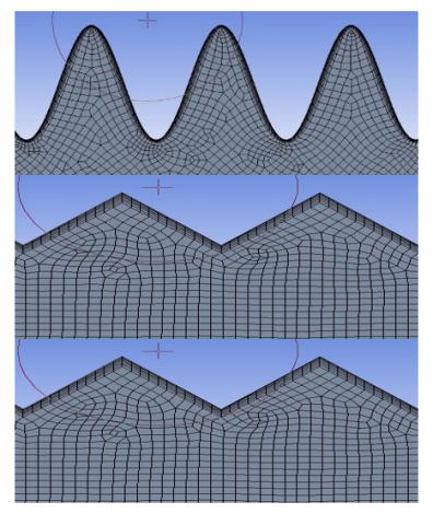
In order to analyze the partial differential equations that govern the fluid flow and heat transfer problems. The flow field should be divided into sub-domains. Different types of sub-domains are possible, such as quadrilaterals and triangles in 2D. The governing equations are then solved inside these sub-domains. It is clear that the mesh is very fine near the corrugation walls to capture the flow behavior. Figure 2 describes the mesh utilized by using FLUENT in the tested corrugation channels. The grid independence exam was conducted at Re=2500 to determine Nusselt number and friction factor values. In the grid independency test, the numbers of grids raise until the difference in results between two consecutive grid sizes became negligible. The gained results are summarized in Table 1 which display the specified grid for all tested cases.
Figure 2. The considerd mesh generation
Table 1. Tested grids for the studied cases for Re=2500
|
Case |
Mesh elements |
Nu |
f |
|
Smooth channel |
26.022 |
8.63 |
0.0393 |
|
26.776 |
9.91 |
0.0381 |
|
|
27.598 |
7.455 |
0.0376 |
|
|
28.150 |
7.311 |
0.0372 |
|
|
Sinusoidal |
44.332 |
15.011 |
0.0521 |
|
44.890 |
14.773 |
0.0567 |
|
|
45.346 |
15.344 |
0.0682 |
|
|
45.897 |
15.411 |
0.0688 |
|
|
Square |
43.365 |
15.862 |
0.073 |
|
43.887 |
16.698 |
0.0796 |
|
|
44.266 |
17.707 |
0.0853 |
|
|
44.793 |
18.212 |
0.0859 |
|
|
Triangular |
71.344 |
23.124 |
0.9343 |
|
71.888 |
23.763 |
0.0963 |
|
|
72.675 |
24.328 |
0.1054 |
|
|
72.879 |
24.379 |
0.112 |
2.3 Governing equations
The governing equations are represented as follows:
Continuity equation [16]:
$\frac{\partial u}{\partial x}+\frac{\partial v}{\partial y}=0$ (1)
Momentum equation [16]
Momentum equation in x-direction:
$u \frac{\partial u}{\partial x}+v \frac{\partial u}{\partial y}=-\frac{1}{\rho} \frac{\partial P}{\partial x}+\frac{\mu}{\rho}\left(\frac{\partial^2 u}{\partial x^2}+\frac{\partial^2 u}{\partial y^2}\right)$ (2)
Momentum equation in y-direction:
$u \frac{\partial v}{\partial x}+v \frac{\partial v}{\partial y}=-\frac{1}{\rho} \frac{\partial P}{\partial y}+\frac{\mu}{\rho}\left(\frac{\partial^2 v}{\partial x^2}+\frac{\partial^2 v}{\partial y^2}\right)$ (3)
Energy equation [16]:
$u \frac{\partial T}{\partial x}+v \frac{\partial T}{\partial y}=\alpha\left(\frac{\partial^2 T}{\partial x^2}+\frac{\partial^2 T}{\partial y^2}\right)$ (4)
where, v, u: dimensionless velocity in x, y directions.
By using Reynolds number (Re) as a basis, the inlet velocity was found by the following formulae:
$R e=\rho u_{\text {avg. }} D_h / \mu$ (5)
The mean heat transfer coefficient can be expressed as follow:
Where the mean wall temperature can be obtained by [17]:
$\mathrm{T}_{\mathrm{w}}=\frac{1}{n} \sum T_{w n}$ (6)
The mean Nusselt number was introduced as follows:
$\mathrm{Nu}=\frac{h \cdot D_h}{k}$ (7)
where, friction factor $(\Delta \mathrm{P})$ termed by using Darcy Weisbach equation as [18]:
$f=\frac{\Delta P \cdot D_h}{\frac{1}{2} \rho u_{a v g}^2 \cdot L}$ (8)
The overall performance factor (η) [19]:
$\eta=\left(N u / N u_o\right) /\left(f / f_0\right)^{1 / 3}$ (9)
2.3.1 Boundary conditions
Basically, the flow is steady, incompressible, laminar, 2-D simulation, with symmetric boundary conditions are utilized on the lateral planes of the domain of fluid, which sets the gradient of pressure normal to the plane and also velocity components, to (zero).
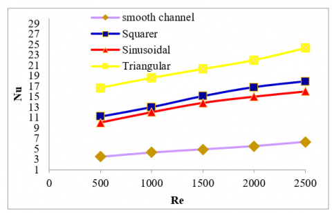
Figure 3 illustrates the values of Nusselt number for the tested cases for all Reynolds number values. Moreover, the highest Nusselt number values are founded at triangular case, wherever, the results indicated that the Nusselt number for triangular case increase by 53% as compared with square case, 71% as compared with the sinusoidal case and 200% as compared with the smooth channel. The increasing in Nu values in presence of corrugations were thought to be due to the recirculation zones formation and intensity flow.
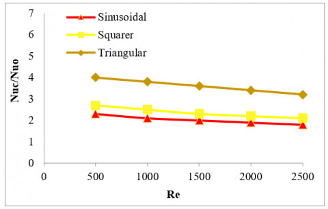
The thermal enhancement ratio (Nuc/Nuo) values have a negative slope as the Reynolds number value increases. Therefore, as display in Figure 4 that’s due to that when the Reynolds number values increase, the increase of Nusselt number in the smooth channel is greater than the increase in Nusselt number with the presence of corrugation. As well as, the values of the thermal enhancement ratio increase at the corrugation in triangular manner, Followed by the square, then the sinusoidal.
Figure 3. The variation of the average Nusselt number for various Renolds number for all cases
Figure 4. The variation of the thermal enhancement ratio for various Reynolds number for all cases
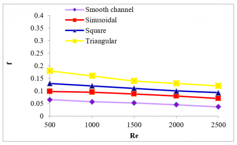
The raising in friction factor values for triangular case compared to the other cases as display in Figure 5 can be attributed to the number of the edges that acting as obstructive the flowing fluid due to increase a larger recirculation zone leading to higher vortex strength led to higher pressure drop.
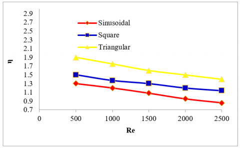
Figure 6 demonstrated the enhancement of thermal-hydrodynamics performance for all Reynolds number values. As shown, the thermal- hydrodynamics performance reduces with increasing of Reynolds number. The Triangular case gives the greatest values in thermal- hydrodynamics performance as contrasted with other cases. Where the greatest value reachs to 189% at Re=500.
Figure 5. The variation of the friction factor for various Reynolds number for all cases
Figure 6. The variation of the thermal- hydrodynamics performance for various Reynolds number for all cases
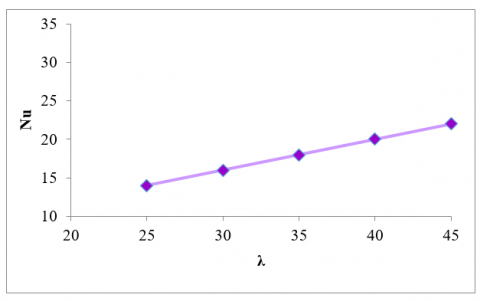
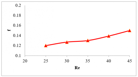
The effect of the angle is an important parameter affecting the heat transfer in the corrugating channel. It can be investigated by varying the angle of the triangular case due to its high results of Nusselt number. the study includes five corrugation angles (25o, 30o, 35o, 40o, 45o). As showing in Figure 7 the smallest corrugation angle 25o gives the smallest value of Nusselt number and this value gradually increases as the angle increases. Furthermore, friction factor values increase as the angle increases as in Figure 8.
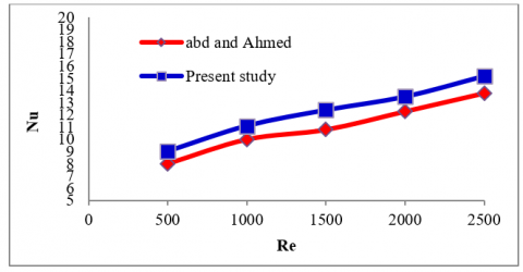
In addition, the gained results of Nusselt number values for current study were compared with the correlations of the works of Abd and Ahmed [5]. They employed V-corrugated channel and the comparison performed at the corrugated angle of 40o, the comparisons are shown in Figure 9 for Nusselt number. The average deviation for average Nusselt number is 11%. This deviation due to the difference in the value of the dimensions of the two channels.
Figure 7. Effect of the corrugated angle on Nusselt number at Re=2500
Figure 8. Effect of the corrugated angle on friction factor at Re=2500
Figure 9. Validation between the current work and Abd and Ahmed [5] for Nusselt number results
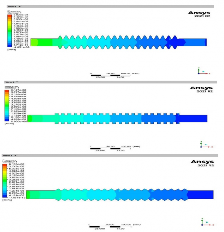
Figure 10 display the pressure drops in the three tested channels (sinusoidal, square and triangular) for Reynolds number 500. The figure show that the rate of the decrease of pressure is almost has near values at the Reynolds number =500.
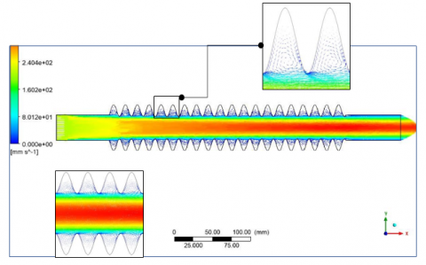
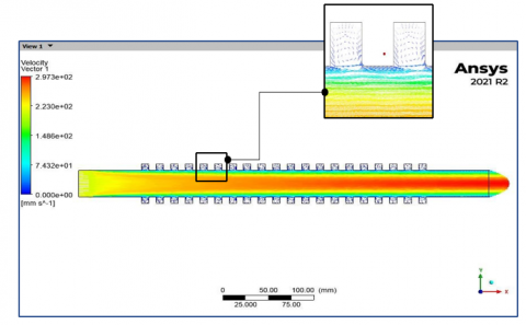
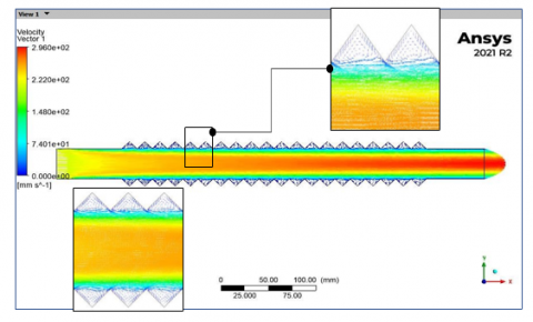
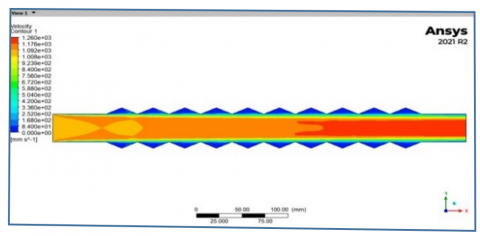
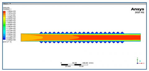
For Re=500, Figure 11 displays the velocity contour for the tested case (sinusoidal, square and triangular) at the center of the channel it can be noticed that the flow almost symmetrical, however for at the channel starts to corrugate, the flow becomes asymmetric. Furthermore, at Re=500 its noticed that the flow velocity increases at the center of the channel and began to decrease towards the upper and the lower wall of the channel due to the viscous flow at the wall. The vortices in the corrugated area repeat the spread that they flow to the downstream with one another in the upper and lower of the channel as in Figure 12. The presence of the corrugations reduced the core stream space that makes the core has the higher velocity.
Figure 10. The pressure in (sinusoidal, square and triangular) channels for Reynolds number 500
Figure 11. Velocity contour (sinusoidal, square and triangular) channels for Reynolds number Re=500
The reason that fluid flow rate and the results of heat transfer rate are increasing at the triangular shape can be attributed to the fact that the oblique surfaces of the triangle and the acute edge can induce a larger recirculation zone behind the triangular corrugation leading to higher vortex strength and turbulence intensity of the flow and forming complex flow, hence enhancing the heat transfer.
Figure 12. Velocity vector (sinusoidal, square and triangular) channels for Reynolds number 500
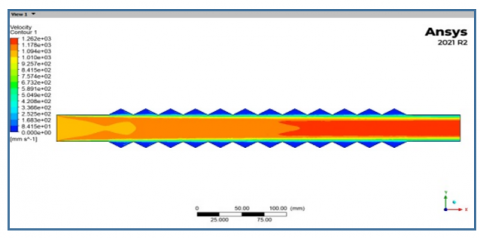
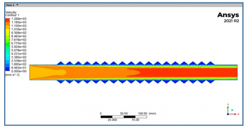
For Re=2500, Figures 13-16 display the velocity contour for the five corrugation angles (25o, 30o, 35o, 40o, 45o) and show the different of the flow behavior.
That can be defined the flow rate will rise with the angle raising value and the flow rate decrease in all cases at area which lies at the upper and the lower of the channel to be smaller and smaller due to the boundary layers.
Figure 13. Velocity contour for 25o degree angled pipe, 2500 Reynolds number
Figure 14. Velocity contour for 30o degree angled pipe, 2500 Reynolds number
Figure 15. Velocity contour for 40o degree angled pipe, 2500 Reynolds number
Figure 16. Velocity contour for 45o degree angled pipe, 2500 Reynolds number
The following conclusions gained from this investigation:
(1) The value of Nu was found to increase with the increase in Reynold numbers values for all cases of the corrugated channel. leading to an overall increase in Nu with Re.
(2) On the contrary, with increase in Reynold number values, fall in friction factor values. The maximum friction factor was noticed in case of (Re)=500. it reached to the maximum value at triangular case of 0.14.
(3) The triangular case gives the best overall performance compared to the sinusoidal and square cases. Where the highest overall performance of the triangular corrugated channel is 180% at Reynold number of 500. Therefore, it is recommended to use the triangular shape in the corrugated passages for applications within the same flow range, as well as those that have dimensions close to the search dimensions.
(4) The value of Nusselt number a gradually increases as the corrugation angle increases.
|
A |
amplitude of the wavy wall [m] |
|
Dh |
hydraulic diameter [m] |
|
f |
friction factor |
|
h |
The mean heat transfer coefficient. W/m2K |
|
H |
height of channel, m |
|
k |
thermal conductivity, W/m k |
|
L |
length of channel, m |
|
m° |
mass flow rate, kg/s |
|
Nu |
mean Nusselt number |
|
Nu0 |
Nusselt number of smooth channel |
|
Nuc |
Nusselt number of corrugated channel |
|
∆p |
pressure drop, pa |
|
Q |
The heat flux. W |
|
Re |
Reynolds number |
|
Tb |
Bulk temperature,K |
|
Tw |
wall temperature, K |
|
Tin |
Inlet temperature. K |
|
Tout |
Outlet temperature. K |
|
Greek symbols |
|
|
ρ |
fluid density, kg m-3 |
|
µ |
Fluid dynamic viscosity, kg s-1 m-1 |
|
ɳ |
overall performance factor |
|
λ |
corrugation angle |
[1] Rahmani, K., Al-Kassir, A., Benalia, M., Djedid, M., Ad, C., Elmsellem, H., Steli, H., Kadmi, Y. (2017). Simulation of fluid flow and heat transfer inside a heat exchanger corrugated channels. Journal of Materials and Environmental Sciences, 8(2): 566-572.
[2] Zhang, L.Z. (2005). Numerical study of periodically fully developed flow and heat transfer in cross-corrugated triangular channels in transitional flow regime. Numerical Heat Transfer, Part A: Applications, 48(4): 387-405. https://doi.org/10.1080/10407780590957314
[3] Goldstein Jr, L., Sparrow, E.M. (1977). Heat/mass transfer characteristics for flow in a corrugated wall channel. Journal of Heat Transfer, 99: 187-195. https://doi.org/10.1115/1.3450667
[4] Ali, M.M., Ramadhyani, S. (1992). Experiments on convective heat transfer in corrugated channels. Experimental Heat Transfer an International Journal, 5(3): 175-193. https://doi.org/10.1080/08916159208946440
[5] Abed, W.M., Ahmed, M.A. (2010). Numerical study of laminar forced convection heat transfer and fluid flow characteristics in a corrugated channel. Journal of Engineering and Sustainable Development, 14(3): 70-85.
[6] Shatnawi, H., Aldossary, A. (2021). Numerical analyses of heat transfer and fluid flow in a corrugated duct. Journal of Engineering and Computer Science (JECS), 22(1): 28-36.
[7] Naphon, P. (2007). Heat transfer characteristics and pressure drop in channel with V corrugated upper and lower plates. Energy Conversion and Management, 48(5): 1516-1524. https://doi.org/10.1016/j.enconman.2006.11.020
[8] Islamoglu, Y. (2008). Effect of rounding of protruding edge on convection heat transfer in a converging–diverging channel. International Communications in Heat and Mass Transfer, 35(5): 643-647. https://doi.org/10.1016/j.icheatmasstransfer.2007.11.002
[9] Gradeck, M., Hoareau, B., Lebouché, M. (2005). Local analysis of heat transfer inside corrugated channel. International Journal of Heat and Mass Transfer, 48(10): 1909-1915. https://doi.org/10.1016/j.ijheatmasstransfer.2004.12.026
[10] Zhang, L.Z. (2005). Numerical study of periodically fully developed flow and heat transfer in cross-corrugated triangular channels in transitional flow regime. Numerical Heat Transfer, Part A: Applications, 48(4): 387-405. https://doi.org/10.1080/10407780590957314
[11] Zhang, L.Z., Chen, Z.Y. (2011). Convective heat transfer in cross-corrugated triangular ducts under uniform heat flux boundary conditions. International Journal of Heat and Mass Transfer, 54(1-3): 597-605. https://doi.org/10.1016/j.ijheatmasstransfer.2010.09.010
[12] Akbarzadeh, M., Rashidi, S., Esfahani, J.A. (2017). Influences of corrugation profiles on entropy generation, heat transfer, pressure drop, and performance in a wavy channel. Applied Thermal Engineering, 116: 278-291.
[13] Islamoglu, Y., Parmaksizoglu, C. (2003). The effect of channel height on the enhanced heat transfer characteristics in a corrugated heat exchanger channel. Applied Thermal Engineering, 23(8): 979-987. https://doi.org/10.1016/S1359-4311(03)00029-2
[14] Mohammed, H.A., Abed, A.M., Wahid, M.A. (2013). The effects of geometrical parameters of a corrugated channel with in out-of-phase arrangement. International Communications in Heat and Mass Transfer, 40: 47-57. https://doi.org/10.1016/j.applthermaleng.2017.01.076
[15] Metwally, H.M., Manglik, R.M. (2004). Enhanced heat transfer due to curvature-induced lateral vortices in laminar flows in sinusoidal corrugated-plate channels. International Journal of Heat and Mass Transfer, 47(10-11): 2283-2292. https://doi.org/10.1016/j.ijheatmasstransfer.2003.11.019
[16] Kundu, J. (2001). Numerical investigation of laminar forced convection in two-dimensional and three-dimensional sinusoidal corrugated ducts. Doctoral dissertation, University of Cincinnati. http://rave.ohiolink.edu/etdc/view?acc_num=ucin998059414.
[17] Mushatet, K., Nashee, S. (2021). Experimental and computational investigation for 3-D duct flow with modified arrangement ribs turbulators. Thermal Science, 25(3 Part A): 1653-1663. https://doi.org/10.2298/TSCI190813093M
[18] Ničeno, B., Nobile, E. (2001). Numerical analysis of fluid flow and heat transfer in periodic wavy channels. International Journal of Heat and Fluid Flow, 22(2): 156-167. https://doi.org/10.1016/S0142-727X(01)00074-1
[19] Tokgöz, N., Alıç, E., Kaşka, Ö., Aksot, M.M. (2018). The numerical study of heat transfer enhancement using Al2O3-water nanofluid in corrugated duct application. Journal of Thermal Engineering, 4(3): 1984-1997.