Johny Anthony![]() | Sujatha Elamparithi*
| Sujatha Elamparithi*![]()
© 2023 IIETA. This article is published by IIETA and is licensed under the CC BY 4.0 license (http://creativecommons.org/licenses/by/4.0/).
OPEN ACCESS
To examine the performance of the rough-porous Rayleigh step slider bearing lubricated with couple stress fluid considering the effect of MHD forms the crux of this article. The bearing surface roughness is assumed to be longitudinal as well as transversal. The expression for longitudinal and transversal roughness are derived by using the stochastic random variable. The modified Darcy’s law is used to derive the pressure in the porous region, The space between the slider filled with couple stress fluid. The stochastic Reynolds equation is derived applying the Christensen’s stochastic approach. Following this the expression for load carrying capacity, fictional force and coefficient of friction are derived. It is observed that work load and frictional force increases when compared with plate without roughness and porous and decreases for coefficient of friction.
couple stress fluid, MHD, porous, Rayleigh step slider bearing, surface roughness
In 1918, Lord Rayleigh structured a new model of slider bearing in which he introduced a step which splits the lubricant film into two zones, namely h1 at the zone through which the lubricant enters the bearing and h2 at the zone through which the lubricant exits the bearing and result holds good when the viscosity of lubricant is considered as function of pressure. The slider bearings have a number of uses in the design of machines and in other types of machine parts, particularly those that involve rectilinear sliding motions. The clutch plate, gear box, thrust bearings, and journal bearings, as well as other parts of the step bearings, are all located in the thrust area. When taking into consideration unique operational situations, it is necessary to have a good understanding of the properties of the bearing. Over the past several years, a number of analysis on the lubricating effectiveness of slider bearings have been undertaken. In order to improve the lubricating efficiency the Newtonian lubricant was combined with long chain polymers. This altered the nature of the lubricant which was termed as non-Newtonian. The application of non-Newtonian fluid as lubricant has increased in the recent years as it has many advantages over the Newtonian fluid as lubericant. Jianming and Gaobing [1] worked the one-dimensional maximum loads of the Rayleigh slider bearing with a power law fluid are determined by using the first-order perturbation expansion. It has been found that the non-newtonian parameter n has an important influence on the load capacity. Naduvinamani and Siddangouda [2] analyzed the impact of couple stress on the porous step slider bearing and concluded that lubricant with couple-stress components have a higher load bearing capacity and a lower coefficient of interaction of bearing surface than the related Newtonian case. In order to determine the impact of side-leakage on the tribological parameters of the bearing, Archibald [3] took into account a stepped slider with a limited width. Maiti [4] used numerical computations to examine the load carrying capacity and skin friction in composite and step slider bearings lubricated with micropolar fluid. On the relationship between normal load and friction force in pre-sliding frictional contacts was explored by Al-Bender and De Moerlooze [5] in 2010. It was brought out that an increasing surface roughness results in an increase of the normal load necessary to reach the predefined normal displacement, as well as an increase of the friction force. Naduvinamani et al. [6] worked in step slider bearing lubricated with Rabinowitsch fluid. The result show that, when compared to the related Newtonian lubricants, dilatant fluids have a much higher load-bearing capacity and a somewhat higher coefficient of friction. But the situation is opposite with pseudoplastic lubricants. The research of magneto-hydrodynamics (MHD) investigates the behavior of fluid that has a capability to conduct electricity is the existence of a magnetic field. Lot of studies looked at how MHD influenced the characteristics of different bearings. To name a few Hughes analysed inclined slider bearing [7] and step slider bearing [8], Snyder’s [9] worked on slider bearing and Kuzma’s [10] on parallel plate slider bearing. The effects of the Hartmann number as well as couple-stress parameter improve the frictional force, load capacity, and coefficient of friction as observed by Hiremath et al. [11]. The two layered porous step slider bearings, developed by Naduvinamani and Ganachari [12], have a work load of higher level and with a capacity to wear of a lower level than single layered porous bearings. Rahmani et al. [13] were able to optimize the load capacity, force developed through interaction of surface, friction coefficient, and flow rate of lubricant of a Rayleigh step bearing. It was shown that the optimum shape with the lowest amount of friction occurs most frequently close to the boundaries of the changeable parameters. Ramanaiah and Sarkar [14] investigated slider bearings with couple stress fluid and discovered that when the couple stress parameter rises, the load capacity and frictional force increase while the frictional coefficient falls. In the analysis of a magnetic fluid based porous rough step bearing’s performance when taking slip velocity into account, Shukla and Deheri [15] concluded that the effect of porosity on the work load and slip velocity is not of considerable level. Though many analysis on the characteristics of step slider bearing have been carried out, the effect of roughness coupled with porosity in a step slider bearing remains untouched till date, when considering it along with MHD. Hence an attempt is made to touch upon these untouched effects in this article.
The geometry of the bearing is shown in Figure 1. The upper face of the slider which has a step cut in it is assumed to be rough in nature. Let h1 be the film thickness at the entry point of the bearing and h2 be the film thickness at the exit level. In such case the step height is obtained as (h2-h1). L1 is assumed to be the length till the point where it drops down to produce a step and L2 is the assumed to be remaining length, so that L1+L2=L. The lower face of the slider bearing is assumed to be made up of porous material of the thickness δ held together by a solid backing. This face is aligned along the x axis and slides in the positive direction of x with a constant velocity U. The entire setup is subjected to a uniform magnetic field of strength B0 which is oriented in the positive direction of y. The desired effects of operating the machinery for varied temperature is obtained by coupling additive to a Newtonian fluid which then converts it a Non Newtonian. The most practically applicable Non Newtonian fluid in automobiles and machinery happens to be couple stress fluid. In the subject of study a very thin couple stress fluid is filled between the gaps of the step slider bearing which act as the lubricant. Assuming the assumptions of thin film lubrication of a hydro magnetic fluid flow to hold good for the given situation, the governing equation for a MHD flow takes the form.
Figure 1. Reyleigh step slider bearing
$\mu \frac{\partial^2 u}{\partial y^2}-\eta \frac{\partial^4 u}{\partial y^4}-\sigma B_0^2 u=\frac{\partial p}{\partial x}+\sigma E_z B_0$ (1)
$\frac{\partial p}{\partial y}=0$ (2)
where, u, v, w are the components related to rate of change of distance in the respective direction of (x, y, z) with respect to time. Pressure which develops between the layers of the slider is denoted by P. μ represent the viscosity of the couple stress fluid that fills the gap between the plates and η the constant that characterizing the material which represents the couple-stress fluid. σ is the electrical conductivity and Ez, the electrical field in the direction of z. Continuity equation considering the 2-D geometry the slider bearing is given by:
$\frac{\partial u}{\partial x}+\frac{\partial v}{\partial y}=0$ (3)
The net current stream vanishes when the bearing is solid, allowing a circuit that exist exterior to the fluid film. Hence:
$\int_{y=0}^H\left(B_0 u+E_z\right) d y=0$ (4)
The boundary condition on the upper and lower surface is given by:
(i) At the upper plate (y=H)
$u=v=0, \frac{\partial^2 u}{\partial y^2}=0$ (5)
(ii) At the lower plate (y=0)
$u=0, \frac{\partial^2 u}{\partial y^2}=0, v=-v^*$ (6)
where, u*, v*, w* are the components related to rate of change of distance in the respective direction of (x, y, z) with respect to time. The modified Darcy’s law for couple-stress fluid in porous tract, which regard for the polar effects is given by:
$\begin{aligned} u^* & =\frac{-k}{\mu}\left[\frac{1}{(1-\beta)} \frac{\partial p^*}{\partial x}\right], \\ v^* & =\frac{-k}{\mu}\left[\frac{1}{(1-\beta)} \frac{\partial p^*}{\partial y}\right]\end{aligned}$
where, k is the rate in which the fluid percolates into the porous zone and $\beta=\frac{\eta}{\mu}\left(\frac{1}{\mathrm{k}}\right)$ represents the fraction of the size of the microstructure to that of the pores holes. Due to the equation of continuity of fluid flow in the porous region, the pressure p* in the porous region is defined using the Laplace equation as follows.
$\frac{\partial^2 p^*}{\partial x^2}+\frac{\partial^2 p^*}{\partial y^2}=0$
Solving Eqns. (1)-(4) by applying the boundary conditions (5) and (6) the expression for velocity in the direction of x is obtained as:
$u=-\frac{h_2^2 H}{2 l \mu \mathrm{M}} \frac{\partial p}{\partial x}\left\{\frac{B^2 \zeta_1-A^2 \zeta_2}{\frac{B^2}{A} \tanh \left(\frac{A H}{2 l}\right)-\frac{A^2}{B} \tanh \left(\frac{B H}{2 l}\right)}\right\}-\frac{U}{2\left(A^2-B^2\right)}\left\{B^2 \zeta_3-A^2 \zeta_4\right\}$ (7)
where,
$\zeta_1=\frac{\sinh \frac{A H}{l}-\sinh \frac{A y}{l}+\sinh \frac{A(H-y)}{l}}{\sinh \frac{A H}{l}}$,
$\zeta_2=\frac{\sinh \frac{B H}{l}-\sinh \frac{B y}{l}+\sinh \frac{B(H-y)}{l}}{\sinh \frac{B H}{l}}$,
$\zeta_3=\frac{\sinh \frac{A H}{l}-\sinh \frac{A y}{l}-\sinh \frac{A(H-y)}{l}}{\sinh \frac{A H}{l}}$,
$\zeta_4=\frac{\sinh \frac{B H}{l}-\sinh \frac{B y}{l}-\sinh \frac{B(H-y)}{l}}{\sinh \frac{B H}{l}}$,
$A=\left[\frac{1+\left(\frac{\mu-l^2 M^2}{\mu}\right)^{\frac{1}{2}}}{2}\right]^{\frac{1}{2}}, B=\left[\frac{1-\left(\frac{\mu-l^2 M^2}{\mu}\right)^{\frac{1}{2}}}{2}\right]^{\frac{1}{2}}$.
The modified Reynolds equation is determined by integrating the conservation of mass Eq. (3) through the film thickness and applying the BC’s (4) and (5):
$-6 \mu U \frac{d H}{d x}+\frac{\partial}{\partial x}\left\{f(H, l, M) \frac{\partial p}{\partial x}\right\}=\left.\frac{12 k}{\mu(1-\beta)} \frac{\partial p^*}{\partial y}\right|_{y=0}$ (8)
Assuming the porous layer thickness δ to be small, the Morgan-Cameron approximation gives that:
$\left.\frac{\partial p^*}{\partial y}\right|_{y=0}=-\frac{\partial^2 p}{\partial x^2} \delta$
$\frac{\partial}{\partial x}\left\{f(H, l, M)+\frac{12 \psi}{\mu(1-\beta)} \frac{\partial p}{\partial x}\right\}=6 \mu U \frac{d H}{d x}$ (9)
where, $f(H, l, M)=\frac{12 H^2}{l M^2}\left\{\frac{A^2-B^2}{\frac{B^2}{A} \tanh \left(\frac{A H}{2 l}\right)-\frac{A^2}{B} \tanh \left(\frac{B H}{2 l}\right)}-\frac{l}{H}\right\}$.
The film thickness region has two parts H(x)=h(x)+hs, where $h(x)=\left\{\begin{array}{l}\mathrm{h}_1 \text { for } 0 \leq \mathrm{x} \leq \mathrm{L}_1 \\ \mathrm{~h}_2 \text { for } \mathrm{L}_1 \leq \mathrm{x} \leq \mathrm{L}\end{array}\right.$ is the mean film thickness and hs is the randomly varying thickness quantity measured from the mean level and thus characterizes the surface roughness. Taking expectation on both sides of the Eq. (9) and applying the Christensen stochastic approach for the surface roughness, the stochastic Reynolds equation is taken up in this form.
$\frac{\partial}{\partial x}\left\{\left(E[f(H, M, l)]+\frac{12 \psi}{\mu(1-\beta)}\right) \frac{\partial E(p)}{\partial x}\right\}=6 \mu U \frac{d E(H)}{d x}$
$E(*)=\int_{-\infty}^{\infty}(*) f\left(h_s\right) d h_s$ (10)
where, the PDF f(hs) of the random variable hs is defined as:
$f\left(h_s\right)=\left\{\begin{array}{ccc}\frac{35}{32} \frac{\left(c^2-h_s\right)^3}{c^7} & \text { if } -c \leq h_s \leq c \\ 0 & \text { elsewhere }\end{array}\right.$.
where, c is the maximum variation from the average film thickness.
The BC’s for pressure is given by:
$p=0$ at $x=0$ (11)
$p=p_c$ at $x=L_1$ (12)
where, pc is the common non-dimensional pressure at the step. On integrating Eq. (10) twice the expression is obtained as:
$p=\frac{6\left(h_i-h_m\right)}{g\left(h_1{ }^*, l^*, M, c^*\right)+\frac{12 \psi}{1-\beta^*}} x+a_1$ (13)
Using the boundary condition (11) and (12), at the entry region:
$a_1=0, p_c=\left\{\frac{\left(h_1-h_m\right)}{g\left(h_1^*, l^*, M, c^*\right)+\frac{12 \psi}{1-\beta^*}}\right\} L_1$ (14)
For the exit region:
$a_1=0, p_c=\left\{\frac{\left(h_m-1\right)}{g\left(1, l^*, M, c^*\right)+\frac{12 \psi}{1-\beta^*}}\right\} L_2$ (15)
The Eqns. (14) and (15) is used to obtain the film thickness when the pressure is maximum hm.
$h_m=\frac{h_1^* L_1^*\left(g\left(1, l^*, M, c^*\right)+\frac{12 \psi}{1-\beta^*}\right)+L_2^*\left(g\left(h_1^*, l^*, M, c^*\right)+\frac{12 \psi}{1-\beta^*}\right)}{L_2^*\left(g\left(h_1^*, l^*, M, c^*\right)+\frac{12 \psi}{1-\beta^*}\right)+L_1^*\left(g\left(1, l^*, M, c^*\right)+\frac{12 \psi}{1-\beta^*}\right)}$ (16)
Now the pressure for the entry region L1 is obtained as:
$p_1=6\left[\frac{\mathrm{L}_2^* \mathrm{~h}_1^*-\mathrm{L}_2^*}{\mathrm{~L}_2^*\left(g\left(\mathrm{~h}_1^*, l^*, M, c^*\right)+\frac{12 \psi}{1-\beta^*}\right)+\mathrm{L}_1^*\left(g\left(1, l^*, M, c^*\right)+\frac{12 \psi}{1-\beta^*}\right) \quad }\right] x$ (17)
The pressure for the exit region L2 is obtained as:
$p_2=6\left[\frac{\mathrm{L}_1^* \mathrm{~h}_1^*-\mathrm{L}_1^*}{\mathrm{~L}_2^*\left(g\left(\mathrm{~h}_1^*, l^*, M, c^*\right)+\frac{12 \psi}{1-\beta^*}\right)+\mathrm{L}_1^*\left(g\left(1, l^*, M, c^*\right)+\frac{12 \psi}{1-\beta^*}\right) \quad }\right]$ (18)
The dimensionless load carrying capacity W is derived by using the Eqns. (17) and (18):
$W=\frac{w h_2^2}{\mu U L^2}=3\left[\frac{L_1^*\left(L_1^* L_2^*-L_1^{* 2}+1\right)\left(h_1^*-1\right)}{L_2^*\left(g\left(h_1^*, l^*, M, c^*\right)+\frac{12 \psi}{1-\beta^*}\right)+\mathrm{L}_1^*\left(g\left(1, l^*, M, c^*\right)+\frac{12 \psi}{1-\beta^*}\right) \quad }\right]$ (19)
The frictional force f per unit width on the surface y=0 is defined by:
$f=\int_0^L\left(\tau_{\mathrm{yx}}\right)_{\mathrm{y}=0} d x$ (20)
where,
$\tau_{\mathrm{yx}}=\mu \frac{\partial u}{\partial y}-\eta \frac{\partial^3 u}{\partial y^3}$ (21)
Using equation number (7) in (21) and replacing it in the Eq. (20) gives the non-dimensional frictional force in the form:
$F=\frac{-f h_2}{\mu U L}=\int_0^1\left[\frac{1}{h}+\frac{h}{2} \frac{d p}{d x}\right] d x$ (22)
$F=\frac{\xi+\left(-1+\frac{1}{\mathrm{~h}_1^*}\right) \mathrm{L}_1^*(\xi)+3 \mathrm{~L}_1^*\left(\mathrm{~h}_1^*-1\right)\left(\mathrm{L}_2^* h_1^*-1+\mathrm{L}_1^*\right)}{\xi}$ (23)
where,
$\xi=\mathrm{L}_2^*\left(g\left(\mathrm{~h}_1^*, l^*, M, c^*\right)+\frac{12 \psi}{1-\beta^*}\right)+\mathrm{L}_1^*\left(g\left(1, l^*, M, c^*\right)+\frac{12 \psi}{1-\beta^*}\right)$.
The coefficient of friction is given by:
$C=\frac{F}{W}$ (24)
The effect of surface roughness and porous on the Reyleigh step slider bearing lubricated with couple stress fluid and with the effect of MHD is taken up for study. The results are discussed using varies parameters like Hartmann number M, entry film thickness $h_1^*$, couple-stress parameter l*, permeability parameter ψ and roughness parameter c*. The comparison is made between the rough-porous surface and without rough porous surface. The present work is compared with Ayyappa Hiremath et al. [11] in Figures 2, 7, 12 with the effect of Hartmann number M=4 and Ramanaiah and Sarkar [14] in Figures 3, 8, 13 without the effect of Hartmann number (M=0). The effects of surface roughness and porous on step slider bearing are mainly analysed in this article. By nature the step slider bearing has high load carrying capacity than other bearing. When introducing roughness and porous the bearing enhance little more load carrying capacity with the presence of couple stress fluid and MHD. The variation of entry level bearing length is analyzed to know which value gives the better load carrying capacity and coefficient of friction.
3.1 Dimensionless work load
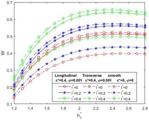
In Figure 2 the work load is plotted for various values of coupling number l* as the film thickness varies. The results when compared with non porous smooth surface [11] gives an enhanced result for the case of porous coupled with roughness. Also the graph shows a similar trend for both the longitudinal and transverse case. In Figure 3 a similar result is arrived at when considering the situation in the absence of MHD [14].
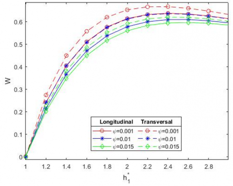
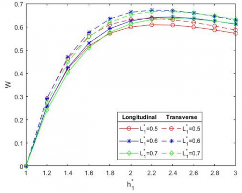
In Figure 4 the load decreases by increasing the value of permeability parameter. Due to the lubricant seeping into the porous region, the pressure drops in the film region. Because of this the load carrying capacity decreases when increasing the permeability parameter. And in Figure 6 the load increases by increasing the value of entry bearing length $L_1^*$.
By varying the surface roughness parameter c* in Figure 5, the load increases with transversal roughness and decreases with longitudinal roughness. The lubricants fill the valleys and ridges of the surface which is rough allowing the lubricants to stay there for a longer time than compared with the smooth solid backing. This accumulation of lubricant helps to carry more load than in the smooth cases and thereby reduces the coefficient of friction between the sliding surfaces.
Figure 2. Sketch of W with $h_1^*$ for different values of l* when M=4
Figure 3. Sketch of W with $h_1^*$ for different values of l* when M=0
Figure 4. Sketch of W with $h_1^*$ for different values of ψ when M=4
Figure 5. Sketch of W with $h_1^*$ for different values of c* when M=4
The Table 1 brings out the numerical comparison between the smooth surface and the rough-porous surface. It can be viewed that the work load is considerably high as in the current work than compared to the smooth surface. In the presence of MHD the load carrying capacity is greater than the absence of MHD.
Table 1. The work load W is tabulated between rough-porous step slider bearing is non rough-porous slider step bearing for varies values of couple-stress parameter l*=0.2, 0.4 and the Hartmann number M=0, 4
|
M |
$h_1^*$ |
L.R |
T.R |
L.R |
T.R |
ψ=0 c*=0 |
|
|
l*=0.2 |
l*=0.2 |
l*=0.4 |
l*=0.4 |
l*=0.2 |
l*=0.4 |
||
|
0 |
1.5 |
0.2729 |
0.2933 |
0.3385 |
0.3678 |
0.1942 |
0.2421 |
|
2 |
0.2795 |
0.2913 |
0.3218 |
0.3367 |
0.1969 |
0.2271 |
|
|
2.5 |
0.2303 |
0.2362 |
0.2531 |
0.2599 |
0.1613 |
0.1775 |
|
|
4 |
1.5 |
0.3987 |
0.4169 |
0.4673 |
0.4925 |
0.3027 |
0.3566 |
|
2 |
0.5358 |
0.5519 |
0.6169 |
0.6382 |
0.4127 |
0.477 |
|
|
2.5 |
0.5607 |
0.5724 |
0.6386 |
0.6536 |
0.4358 |
0.4978 |
|
Figure 6. Sketch of W with $h_1^*$ for different values of $L_1^*$ when M=4
3.2 Dimensionless frictional force
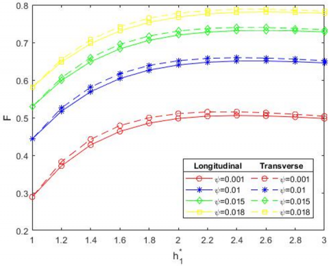
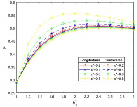
In Figure 7 the frictional force is plotted for various values of coupling number l* as the film thickness varies. The results when compared with non porous smooth surface [11] gives an enhanced result for the case of porous coupled with roughness. Also the graph shows a similar trend for both the longitudinal and transverse case. In Figure 8 a similar result is arrived at when considering the situation in the absence of MHD [14]. In Figures 9, 10 and 11 the variation of non-dimensional Frictional force F with height $h_1^*$ and with the presence of MHD (M=4) for different values of permeability parameter ψ, surface roughness parameter c* and bearing length $L_1^*$ respectively are plotted. The frictional force increases by increasing the values of permeability parameter ψ and entry bearing length $L_1^*$. By varying the surface roughness parameter c*, the frictional force increases with transversal roughness and decreases with longitudinal roughness The values in the lower part of the Figures 7 and 8 represent the results obtained through literatures [11, 14]. This brings out that the frictional force is much enhanced in the present study when compared to the work already present.
The Table 2 brings out the numerical comparison between the smooth surface and the rough-porous surface. It can be viewed that the frictional force F is considerably high in the current work than compared to the smooth surface.
The frictional force increases by increasing the values of Hartmann number from 0 to 4.
Figure 7. Plot of F with $h_1^*$ for distinct values of l* when M=4
Figure 8. Plot of F with $h_1^*$ for distinct values of l* when M=0
Figure 9. Sketch of F with $h_1^*$ for different values of ψ when M=4
3.3 Dimensionless coefficient of friction
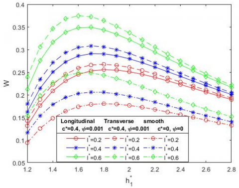
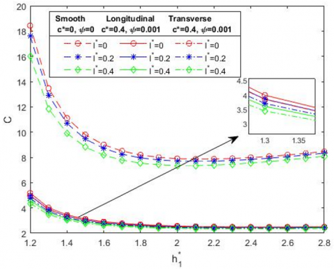
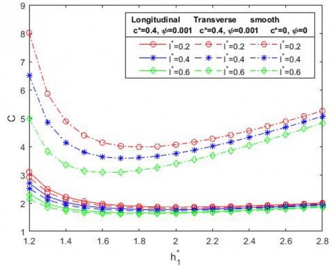
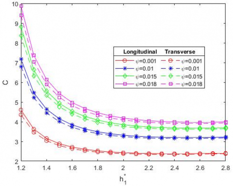
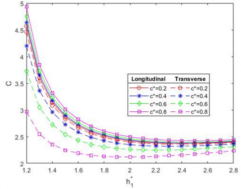
In Figure 12 the coefficient of friction C is plotted for various values of coupling number l* as the film thickness varies. The results when compared with non porous smooth surface [11] gives an enhanced result for the case of porous coupled with roughness. Also the graph shows a similar trend for both the longitudinal and transverse case. In Figure 13 a similar result is arrived at when considering the situation in the absence of MHD [14]. In Figures 14, 15 and 16 the variation of non-dimensional coefficient of frictional C with height $h_1^*$ and with the presence of MHD (M=4) for different values of porosity parameter ψ, surface roughness parameter c* and bearing length $L_1^*$ respectively are plotted. The coefficient of friction increases by increasing the value of permeability parameter ψ and bearing length $L_1^*$. By varying the surface roughness parameter c*, the coefficient of friction increases with longitudinal roughness and decreases with transversal roughness.
Figure 10. Sketch of F with $h_1^*$ for different values of c* when M=4
Figure 11. Sketch of F with $h_1^*$ for different values of $L_1^*$ when M=4
Table 2. The Frictional force F is compared between rough-porous slider step bearing and non rough-porous slider step bearing for distinct values of couple-stress parameter l*=0.2, 0.4 and the Hartmann number M=0, 4
|
M |
$h_1^*$ |
L.R |
T.R |
L.R |
T.R |
ψ=0 c*=0 |
|
|
l*=0.2 |
l*=0.2 |
l*=0.4 |
l*=0.4 |
l*=0.2 |
l*=0.4 |
||
|
0 |
1.5 |
0.1719 |
0.1788 |
0.1934 |
0.2036 |
0.0736 |
0.076 |
|
2 |
0.1645 |
0.1684 |
0.1785 |
0.1835 |
0.0739 |
0.0769 |
|
|
2.5 |
0.1424 |
0.1442 |
0.15 |
0.1521 |
0.0725 |
0.0749 |
|
|
4 |
1.5 |
0.4029 |
0.409 |
0.449 |
0.4574 |
0.267 |
0.2928 |
|
2 |
0.4486 |
0.4540 |
0.4991 |
0.5062 |
0.2906 |
0.3199 |
|
|
2.5 |
0.457 |
0.4609 |
0.5063 |
0.5113 |
0.3118 |
0.3436 |
|
The Table 3 brings out the numerical comparison between the smooth surface and the rough-porous surface. It can be viewed that the coefficient of friction C is considerably high as in the current work than compared to the smooth surface.
The coefficient of friction increases by increasing the values of Hartmann number from 0 to 4.
Tables 4, 5, 6 bring out the fact that values of W and F are high for the transversal roughness when compared with longitudinal roughness and the values are in a reciprocal trend for the analysis of C.
Figure 12. Sketch of C with $h_1^*$ for different values of l* when M=4
Figure 13. Sketch of C with $h_1^*$ for different values of l* when M=0
Table 3. The analysis of coefficient of friction C is compared with rough-porous slider step bearing by non rough-porous slider step bearing for varies values of couple-stress parameter l*=0.2, 0.4 and the Hartmann number M=0, 4
|
M |
$h_1^*$ |
L.R |
T.R |
L.R |
T.R |
ψ=0 c*=0 |
|
|
l*=0.2 |
l*=0.2 |
l*=0.4 |
l*=0.4 |
l*=0.2 |
l*=0.4 |
||
|
0 |
1.5 |
0.2729 |
0.2933 |
0.3385 |
0.3678 |
0.1942 |
0.2421 |
|
2 |
0.2795 |
0.2913 |
0.3218 |
0.3367 |
0.1969 |
0.2271 |
|
|
2.5 |
0.2303 |
0.2362 |
0.2531 |
0.2599 |
0.1613 |
0.1775 |
|
|
4 |
1.5 |
0.3987 |
0.4169 |
0.4673 |
0.4925 |
0.3027 |
0.3566 |
|
2 |
0.5358 |
0.5519 |
0.6169 |
0.6382 |
0.4127 |
0.477 |
|
|
2.5 |
0.5607 |
0.5724 |
0.6386 |
0.6536 |
0.4358 |
0.4978 |
|
Figure 14. Sketch of C with $h_1^*$ for different values of ψ when M=4
Figure 15. Sketch of C with $h_1^*$ for different values of c* when M=4
Figure 16. Sketch of C with $h_1^*$ for different values of $L_1^*$ when M=4
Table 4. The values of work load W, Frictional force F and coefficient of friction C are analysed by varying the value of roughness parameter c*
|
$h_1^*$ |
c*=0.2 |
c*=0.2 |
c*=0.4 |
c*=0.4 |
c*=0.6 |
c*=0.6 |
|
|
L.R |
T.R |
L.R |
T.R |
L.R |
T.R |
||
|
W |
1.2 |
0.2453 |
0.253 |
0.2433 |
0.2609 |
0.2404 |
0.2734 |
|
2 |
0.6196 |
0.6289 |
0.6169 |
0.6382 |
0.6132 |
0.6521 |
|
|
2.8 |
0.6284 |
0.6337 |
0.6269 |
0.6389 |
0.6248 |
0.6465 |
|
|
F |
1.2 |
0.3735 |
0.3761 |
0.3716 |
0.3826 |
0.3687 |
0.3979 |
|
2 |
0.5 |
0.5031 |
0.4979 |
0.5108 |
0.4944 |
0.5261 |
|
|
2.8 |
0.4987 |
0.5002 |
0.4976 |
0.5038 |
0.4959 |
0.5107 |
|
|
C |
1.2 |
4.5675 |
4.4602 |
4.6376 |
4.199 |
4.7569 |
3.7288 |
|
2 |
2.4211 |
2.4001 |
2.4356 |
2.35 |
2.4604 |
2.261 |
|
|
2.8 |
2.401 |
2.3893 |
2.409 |
2.3615 |
2.4228 |
2.3124 |
Table 5. The values of work load W, Frictional force F and coefficient of friction C are analysed by varying the value of porosity ψ
|
$h_1^*$ |
ψ=0.001 |
ψ=0.001 |
ψ=0.01 |
ψ=0.01 |
ψ=0.015 |
ψ=0.015 |
|
|
L.R |
T.R |
L.R |
T.R |
L.R |
T.R |
||
|
W |
1.2 |
0.2404 |
0.2734 |
0.2141 |
0.2399 |
0.2019 |
0.2246 |
|
2 |
0.6132 |
0.6521 |
0.5771 |
0.6114 |
0.5588 |
0.5909 |
|
|
2.8 |
0.6248 |
0.6465 |
0.6034 |
0.6237 |
0.5921 |
0.6116 |
|
|
F |
1.2 |
0.3716 |
0.3826 |
0.5172 |
0.5257 |
0.5988 |
0.6064 |
|
2 |
0.4979 |
0.5108 |
0.6401 |
0.6515 |
0.7197 |
0.7304 |
|
|
2.8 |
0.5017 |
0.5089 |
0.6488 |
0.6556 |
0.7308 |
0.7373 |
|
|
C |
1.2 |
4.5966 |
4.353 |
7.1817 |
6.8094 |
8.822 |
8.3781 |
|
2 |
2.4271 |
2.3795 |
3.3144 |
3.2418 |
3.8482 |
3.7616 |
|
|
2.8 |
2.4043 |
2.3779 |
3.2188 |
3.1785 |
3.6939 |
3.6459 |
Table 6. The values of work load W, Frictional force F and coefficient of friction C are analysed by varying the value of bearing length $L_1^*$
|
|
$h_1^*$ |
$L_1^*$=0.5 |
$L_1^*$=0.5 |
$L_1^*$=0.6 |
$L_1^*$=0.6 |
$L_1^*$=0.7 |
$L_1^*$=0.7 |
|
L.R |
T.R |
L.R |
T.R |
L.R |
T.R |
||
|
W |
1.2 |
0.2582 |
0.292 |
0.2563 |
0.2907 |
0.2404 |
0.2734 |
|
2 |
0.5991 |
0.6317 |
0.6256 |
0.6625 |
0.6132 |
0.6521 |
|
|
2.8 |
0.5864 |
0.6032 |
0.6251 |
0.645 |
0.6248 |
0.6465 |
|
|
F |
1.2 |
0.3191 |
0.3303 |
0.3477 |
0.3591 |
0.3716 |
0.3826 |
|
2 |
0.4341 |
0.4449 |
0.4724 |
0.4848 |
0.4979 |
0.5108 |
|
|
2.8 |
0.4298 |
0.4354 |
0.4723 |
0.4789 |
0.5017 |
0.5089 |
|
|
C |
1.2 |
3.6776 |
3.5038 |
4.0355 |
3.8338 |
4.5966 |
4.353 |
|
2 |
2.1677 |
2.134 |
2.2587 |
2.2194 |
2.4271 |
2.3795 |
|
|
2.8 |
2.1957 |
2.1771 |
2.2626 |
2.2408 |
2.4043 |
2.3779 |
The comparative work between two different kind of systems are carried out in this article. The existing system is a step slider which is non porous and smooth. This is compared with a porous rough step slider in the presence of MHD in the present work. The characteristics that influence the nature of the bearing namely permeability, coupling number, roughness parameter both longitudinal and transversal, magnetic field strength and the entry level bearing length are varied for their effect and the outputs have been both plotted as well as tabulated. These emanate the following result.
·The work load and frictional force increase when increasing the value of couple-stress parameter l*.
·The coefficient of friction decreases when increasing the value of couple stress parameter l*.
·The frictional force F and coefficient of friction C increases when increasing the value of permeability ψ, but it is inversely proportional to load carrying capacity.
·The load carrying capacity W, frictional force F and coefficient of friction C increases when increasing the value of entry level bearing length $L_1^*$.
·In the variation of surface roughness parameter c*, the force developed through interaction of surface and load carrying capacity increases with transversal roughness and decreases with longitudinal roughness, but it is inversely proportional to coefficient of friction.
·Considering the variation of Hartmann number M from 0 to 4, there is an enhancement in the load carrying capacity, frictional force and coefficient of friction.
·Work load is directly proportional to the surface roughness and bearing length but it is inversely proportional to permeability.
|
C |
Non dimensional coefficient of friction |
|
F |
Non dimensional frictional force |
|
L |
Bearing length (L1+L2) |
|
M |
Hartmann number |
|
U |
sliding velocity of the lower part |
|
W |
Non dimensional load carrying capacity |
|
Bo |
Strength of applied magnetic field |
|
h(x) |
mean film thickness |
|
hs |
stochastic film thickness measured from the nominal mean levels of the bearing surface |
|
l* |
non-dimensional couple stress parameter |
|
u, v, w |
velocity components in the (x, y, z)-directions respectively |
|
u*, v* |
modified Darcy velocity components in the x and y direction respectively |
|
pc |
non dimensional pressure at the step |
|
Greek symbols |
|
|
η |
material constant responsible for the couple stress fluid property |
|
μ |
lubricant viscosity |
|
ψ |
Permeability parameter |
[1] Wang, J.M., Jin, G.B. (1989). The optimal design of the Reyleigh slider bearings with a power law fluid. Wear, 129: 1-11. https://doi.org/10.1016/0043-1648(89)90274-3
[2] Naduvinamani, N.B., Siddangouda, A. (2007). A note on porous Rayleigh step bearing Lubricated with couplestress fluids. Journal of Engineering Tribology, 221(5): 615-621. http://dx.doi.org/10.1243/13506501JET206
[3] Archibald, F.R. (1950). A simple hydrodynamic thrust bearing. Transactions of the American Society of Mechanical Engineers, 72(4): 393-400. https://doi.org/10.1115/1.4016694
[4] Maiti, G. (1973). Composite and step slider bearings in micropolar fluid. Japanese Journal of Applied Physics, 12(7): 1058. https://doi.org/10.1143/JJAP.12.1058
[5] Al-Bender, F., De Moerlooze, K. (2010). On the relationship between normal load and friction force in pre-sliding frictional contacts. Part 1: Theoretical analysis. Wear, 269(3-4): 174-182. https://doi.org/10.1016/j.wear.2010.02.010
[6] Naduvinamani, N.B., Patil, S., Siddapur, S.S. (2017). On the study of Rayleigh step slider bearings lubricated with non-Newtonian Rabinowitsch fluid. Industrial Lubrication and Tribology, 69(5): 666–672. https://doi.org/10.1108/ILT-06-2016-0126
[7] Hughes, W.F. (1963). The magnetohydrodynamic inclined slider bearing with a transverse magnetic field. Wear, 6(4): 315-324. https://doi.org/10.1016/0043-1648(63)90164-9
[8] Hughes, W.F. (1963). The magnetohydrodynamic finite step slider bearing. Journal of Basic Engineering, 85(1): 129-136. https://doi.org/10.1115/1.3656508
[9] Snyder, W.T. (1962). The magnetohydrodynamic slider bearing. Journal of Fluids Engineering, 84(1): 197-202. https://doi.org/10.1115/1.3657252
[10] Kuzma, D.C. (1964). The magnetohydrodynamic parallel plate slider bearing. ASME Journal of Basic Enginnering, 87(3): 778-780. https://doi.org/10.1115/1.3650685
[11] Hiremath, A.G., Hanumagowda, B.N., Kashinath, B., Neela, D. (2020). Analysis of MHD effect on rayleigh step slider bearing lubricated with couple-stress fluids. International Journal of Mechanical and Production Engineering Research and Development, 10(3): 9055-9066. https://doi.org/10.24247/ijmperdjun2020860
[12] Naduvinamani, N.B., Ganachari, R. (2022). Double-layered porous rayleigh step slider bearings lubricated with couplestress fluids. Indian Journal of Science and Technology, 15(28): 1389-1398. https://doi.org/10.17485/IJST/v15i28.33
[13] Rahmani, R., Shirvani, A., Shirvani, H. (2009). Analytical analysis and optimisation of the Rayleigh step slider bearing. Tribology International, 42(5): 666-674. https://doi.org/10.1016/j.triboint.2008.09.002
[14] Ramanaiah, G., Sarkar, P. (1979). Slider bearings lubricated by fluids with couple stress. Wear, 52(1): 27-36. https://doi.org/10.1016/0043-1648(79)90193-5
[15] Shukla, S., Deheri, G. (2013). Effect of slip velocity on magnetic fluid lubrication of rough porous rayleigh step bearing. Journal of Mechanical Engineering and Sciences (JMES), 4: 532-547. https://doi.org/10.15282/JMES.4.2013.17.0050