Ali A. Abdulrasool*![]() | Mohammed W. Aljibory
| Mohammed W. Aljibory![]() | Abdalrazzaq K. Abbas
| Abdalrazzaq K. Abbas![]() | Muhsen M. Al-Silbi
| Muhsen M. Al-Silbi![]()
© 2023 IIETA. This article is published by IIETA and is licensed under the CC BY 4.0 license (http://creativecommons.org/licenses/by/4.0/).
OPEN ACCESS
Heat exchangers are still in high demand for the majority of industrial applications. A double pipe heat exchanger, also known as a DPHE, is a device that is used to transfer heat from hot to cold liquids, primarily water. It is therefore of great importance to discover new methods improving their thermal-hydraulic performance. In the current computational study, the focus will be on a helical turbulator constructed with small perforations and built inside the annulus of DPHE. First, our results are validated against their counterparts of an experiment conducted by others to examine the flow under the effect of a helical solid wire and/or global air blown inside the annulus. Second, four cases are introduced to the flow inside the helical tube only, two different mass flow rates for single and two phase flows. All findings suggest that the optimal performance comes from pumping some quantity of the working fluid inside the helical tube with roughly 600% and 45% increase in terms of overall heat transfer coefficient and thermal effectiveness, respectively, compared to that of non-perforated turbulator. Furthermore, for this proposed device, single-phase flow with or without oscillations outperforms two-phase and/or steady flow.
double-pipe heat exchanger (DPHE), perforated turbulator (PT), two methods of fluid injection, two-phase flow, oscillatory flow, thermal-hydraulic performance, exergy calculations
Heat exchangers have a dominated presence in various engineering fields, where the heat plays a significant role. These areas of application include, but are not limited to, power plants, chemical processing systems, food processing systems, automobile radiators, waste heat recovery units, heating and air conditioning systems, and refrigeration systems. For example, double-pipe heat exchangers are crucial when sensible fluid heating or cooling procedures are required and compact heat transfer zones are available. The oil cooler is an example of such a process. Thus, there have been numerous studies conducted to improve their design, performance, and types of working fluid inside them. The researches [1, 2] offer the most in-depth reviews of this topic. Obviously, the purpose of these devices is to transfer heat from one medium to another while no work other than the pumping power for fluids is imposed. Usually, to maximize the rate of heat transfer while maintaining the fluid pressure drop reasonably reduced appears to be a design challenge. Nevertheless, two categories can be found to enhance the thermal performance: active and passive. When a system needs to be supplemented with external power in order to achieve better outcomes, the technique is referred to as active. The passive method, however, such as manipulating with the geometry by inserting twisted tapes, wire coils, swirl flow generators, or mounting ribs, conical rings, wings, and so on, is still preferable.
The evaluation [3] was to the pressure drop and heat transfer rates for a horizontal DPHE incorporating wire coil. The inner pipe was 8.92 (mm) in diameter while the outer diameter was 9.52 (mm). The iron wire of one millimeter was inserted with a diameter of 7.8 (mm) inside the DPHE's shell. The experiments were conducted at mass flow rates that range from 0.01 to 0.07 (kg/s) and from 0.04 to 0.08 (kg/s) for cold and hot waters, respectively. The inlet cold and hot water temperatures were correspondingly between 15 and 20 and between 40 and 45℃. It was found that the coil-wire inserts significantly improve the heat transfer, particularly in the laminar flow regime.
The experimental work [4] studied the consequences of inserting wire coils together with twisted tapes under a uniform heat-flux in circular channel utilizing air as a working fluid. The findings revealed that the use of wire coils and twisted tapes combined results a double increase in heat transfer compared with employing the wire coil or twisted tape separately. Under the same circumstances, twisted tape and wire coils with smaller twist and coil pitch ratios are better than those with bigger ratios.
With respect to the shell-and-tube heat exchangers of porous passages, named helixchangers, helical baffles are more commonly used. They usually lead to reasonable pressure drop, vibration, and fouling effect with a greater heat transfer boost. The paper [5] provides a comprehensive survey of developments and advancements in helixchangers, including the combination of multiple shell-pass helixchangers, continuous or mixed helical baffles, and discontinuous helical baffles. They found that helixchangers outperform traditional segmental baffled heat exchangers in terms of flow and heat transfer, according to several experiments and computer simulations.
In the work [6], the wire coil was attached to the inner pipe interrupting the developed boundary-layer to increase turbulence activity and fluid mixing and thus the heat transfer. The achieved enhancements in the mean Nusselt numbers using the wire coil were found to be 110%, 116%, and 112%, respectively, in comparison to the plain pipe. Accordingly, the friction factor was around 11%, 10%, and 9% measured with respect to the plain case at the same Reynolds number.
The authors [7] provided a full survey on passive heat transfer enhancements. They determined that the twisted tape inserts perform better in the laminar flow than in the turbulent flow. Other techniques such as ribs, conical nozzles, and conical rings are generally more effective in the turbulent flow because the shorter pitch length leads to stronger swirling flow and longer residence time in the tube. Also, the helical screw tape can promote a higher heat exchange rate than the twisted tape. When the pressure drop loss is considered, the wire coil provides superior overall performance.
Experimental tests [8] to the double pipe heat exchanger in terms of heat transfer coefficient for Reynolds numbers between 4,000 and 14,000. The investigation was carried out in turbulent regime for both parallel and counter arrangements, where the cold fluid is inside the annulus. Turbulators were made of 2 (mm) diameter circular cross-section and were turned into coils with various pitches of 5, 6, 12, and 20 (mm). The introduction of coiled circular wire resulted in a significant increase to the heat transfer rate but also an elevation to the pressure drops, which is mostly dependent on spring pitches and wire thickness. The results demonstrated that higher coil pitch values and higher mass flow rates enhance the relative average Nusselt number of counter flow up to 450%, while higher coil pitch values and higher mass flow rates can improve the relative average Nusselt number of parallel flows up to 400%.
In order to improve the performance of heat exchanger, various turbulators were examined by Sheikholeslami et al. [9], including coiled tubes, extended surfaces (fin, louvered strip, winglet), rough surfaces (corrugated tube, rib), and swirl flow devices (twisted tape, conical ring, snail entry turbulator, vortex rings, coiled wire). The wire coil provides the highest overall performance when the pressure drop penalty is taken into consideration. The use of coiled square wire turbulators considerably increases heat transfer and friction loss when compared to smooth wall tubes. The pressure drop across the tube is a result of drag forces, flow obstruction, turbulence amplification, and rotating flow brought on by the helical rib. The thermal performance factor increases when a conical ring has more perforated holes.
It can be seen from the literature, for example, the paper [9], if the Prandtl number is high, the twisted tape will not serve as good as other inserts such as wire coil regarding the thermo-hydraulic performance. This is due to the fact that the wire coil induces more turbulence than the tape does when the Prandtl number is large, indicating that the hydrodynamic boundary layer is thick. The use of swirl flow devices enhances convective heat transfer in two ways: by swirling into the bulk flow and by breaking the boundary layer at the tube's surface. That is to say, such devices produce turbulence and superimpose vortex motion (swirl flow), which induces the boundary layer and, as a result, causes a larger Nusselt number and a better heat transfer coefficient.
Measurements were taken by San et al. [10] to the pressure drop, heat transfer, and water flow rate in a smooth pipe accompanied by coiled-wire inserts. The ratios of coil pitch to tube inner diameter and wire diameter to tube inner diameter, or e/d and dc/d, respectively, were from 0.0725 to 0.134 and 1.304 to 2.319. The Nusselt number rose directly with the e/d value and inversely with the dc/d value. It should be emphasized that the optimal settings were e/d = 0.101 and dc/d = 2.319 for air and e/d = 0.101 and dc/d = 1.739 for water, where these values were proved to be in favor of better thermal performance.
The researchers [11] carried out an experiment for heat exchanger with internal helical coil at a range of 14400 < Re < 42900, in the turbulent regime. They examined the effect of the Reynolds number, wire diameter, and coil pitch ratio on the Nusselt number and friction factor. Within these analyzed range of various parameters, the biggest achievements in the thermal performance were from 100 to 128%.
The paper [12] provides a detailed review of experimental and numerical studies conducted by various researchers in order to improve heat transfer through the use of roughness elements (vortex generator) of various shapes, sizes, and orientations. An effort was given to select the best roughness shape for maximum heat transfer with minimum pressure drop. Also, it was restated that the high rate of heat transfer with the existing of objects such as twisted tape, wire coils, ribs, and dimples is primarily due to the flow blockage, flow partitioning, and secondary flow.
A shell and coiled-tube heat exchanger were experimentally investigated by Panahi and Zamzamian [13] in which a wire was used inside the helically coiled tube as a turbulator. In the first mode, the fluid of coiled tube was water, and in the second mode, the fluid of coiled tube was air. Findings showed that this type of turbulator can be incorporated in the heat exchanger and significantly increase the overall heat transfer coefficient and obviously pressure drop.
In the study [1], the majority of data pertaining to the performance of heat exchanger with tabulator was compiled from the literature. They concluded that the twisted turbulators are evidently more functioned than others. Also, the devices that have perforated baffles are thermally superior among those without holes.
A passive enhancement approach used by Pérez-García et al. [14] was examined at Reynolds number ranging from 200 to 2000. The transition shape parameter (TSP), a new dimensionless measure, was utilized to classify the wire coils based on their hydraulic performance. This criterion can predict the friction factor alterations with Reynolds number in the transition region with and without inserting the wire coil. When compared to the high TSP group (TSP > 750), the low TSP group (TSP = 10) exhibited an abrupt transition. The intermediate TSP (between 10 and 750) had three wire-coil subgroups distinguished by the hydraulic behavior.
An experimental investigation was carried out by Maithani and Kumar [15] to determine the impact of helical perforated twisted tape on the thermal and hydrodynamic performance of heat exchanger. This study covers diameter ratio (tube per helical diameters), relative pitch ratio (perforated pitch per length of the tape), perforation index (perforated per total areas), and Reynolds number (Re). The best records were noted at diameter ratio of 0.65, relative pitch ratio of 0.086, and perforation index of 10%. For the range of parameters investigated, it was achieved a high thermal-hydrodynamic performance of 2.12.
The researcher [16] used a helical coil of a 19 (mm) pitch with an average helix diameter of 305 (mm). Adjustments were made for the temperature and water flow rate, in the annulus and helical coil side, at different values. The design of the heat exchanger was determined with a full range of data for outlet conditions as functions of inlets. The input parameters include the amount of constant heat flux, flow rate and temperature of primary and secondary fluids. Results showed that there is a rise in the overall heat transfer coefficient and thus heat transfer rate when the mass flow rate of cold water in the coil or hot water in the annulus is increased.
The experiment of Bhattacharyya and Paul [17] was for turbulent forced convection using circular-hole spring tape (CHST) placed in a circular tube. For a wide range of Reynolds numbers (from 10,000 to 50,000), the CHST inserts with varying hole and spring ratios were explored. Results indicated that using CHST can improve heat transfer by 35% and 51% when compared to other inserts and plain tube, respectively. Additionally, a study on entropy generation demonstrated that the irreversibility rises noticeably as the diameter ratio and Reynolds number increase. The thermo-hydraulic performance was roughly more than unity in all situations.
The work [18] was an experimental investigation for the effects of air bubble injection on the efficiency of a horizontal heat exchanger. The differences in the number of thermal units (NTU), energy loss, and efficiency caused by the injection of air bubbles at various air flow rates were assessed. As the air bubbles were injected, the heat exchanger's efficiency and NTU significantly increased. Thus, it is believed that the motion of air bubbles induces disturbances and then the level of turbulence in the shell side flow to rise, increasing the value of NTU and energy loss.
A shell and multi-tube heat exchanger using two air injection methods: parallel (upper and lower nozzles) and transverse (side nozzles) were installed within the experimental apparatus of El-Said and Abou Alsood [19]. In all test settings, the second approach (cross injection) had a greater impact on the heat exchanger efficiency, number of transfer units (NTU), and overall heat transfer coefficient (U) than the first way (parallel injection). In comparison to parallel injection, the cross injection resulted in a larger shell side pressure loss.
Multiple types of injectors were used by Heyhat et al. [20] to blow air into the annulus side of heat exchanger. Experimental data were collected for different annulus side and inner tube flow rates. Exegetic analysis was added to examine the impact of air flow rate and heat exchanger positioning angle on the overall performance. The collected data showed that the overall heat transfer coefficient could be raised by 10.3 to 149.5% by injecting air bubbles.
In the apparatus of the paper [21], a ring tube was located at the bottom of vertical annular pipe, which contains holes to allow air bubbles to flow into the annular space of heat exchanger. Due to the difference in density between the liquid and these tiny bubbles, there was high vibration, turbulence, and heat transfer. It was concluded that the heat exchanger performance can be enhanced by creating perforations on a plastic tube and then choosing the right number and dimension of holes. The Nusselt number and dimensionless exergy destruction were highly changed by roughly 57% and 30%, respectively.
Air was supplied to the coil side of a horizontal shell and coiled tube heat exchanger in the study by Khorasani et al. [22]. The findings showed that air bubbles injection into the heat exchanger enhanced the thermal effectiveness. In a T-junction of the instrument [23], outside the heat exchanger, hot water and air were mixed before moving inside the heat exchanger's inner tube. The flow rate of hot water was maintained at 2 (lit/min). Four potential flow rates: 3, 4, 5, and 6 (lit/min) were taken into consideration for the hot water flow rate. The results showed an increase in the heat transfer coefficient by 33%, and in the number of transfer units by 38%, respectively.
Researchers [24] studied the effect of air bubble injection on the thermal performance of a counter flow heat exchanger with vertical, helical coil tube. The effectiveness was increased due to the air bubbles to hot water, and at a flow rate of 3.5 (lit/min), the maximum effectiveness value reached 0.22. With compressing more air bubbles from 0.1 to 0.31 (lit/min) at a Reynolds number of 9823, the friction factor jumped to high values. The maximum enhancement ratio of Nusselt number was between 2.4 and 3.1 with air flow rate of 3.5 (lit/min) and Reynolds number between 9823 and 48028. With air bubble injection rate of 3.5 (lit/min), the maximum thermal performance factor was 1.33 whereas the exergy loss rose from 74 to 88%.
The study [25] tried the combined impact of twisted tape turbulators and air injection on the enhancement of heat transfer. It was reported that the air injection increases the pressure drop and heat transfer coefficient by up to 62 and 30.3%, respectively. The cost-benefit ratio was estimated to be acceptable at air and water flow rates of 1 and 5 (lit/min) with the best value of approximately 0.93. Other researchers, including [26], investigated the effect of rotating turbulators on forced convection to produce entropy and enhance heat transfer. With the entropy generation being significantly reduced while the thermal performance was noticeably improved, this supports the assumption that the rotating turbulator is more energetic.
The objective of the work [27] was to quantitatively analyze the relation between the use of twisted tape and the heat transfer rate and friction factor for double pipe heat exchanger. It was reported that the Nusselt number and friction factor for a plain-tube flow can be predicted more precisely by the turbulence model SST k-ω than by conventional standard k-ϵ, RNG k-ϵ, and Realizable k-ϵ. The twisted tape caused swirl flows in two areas: one that is adjacent to the twisted tape wall and another one is in the core region. The usage of triangular-cut twisted tape was found to improve fluid mixing because of swirl phenomena. To assess the thermal-hydraulic performance of two improved heat transfer tubes, Santos et al. [28] conducted a computational fluid dynamics analysis. They discovered that for the Nusselt number and friction factor prediction, the SST k-ω provides the best accuracy.
The experimental and numerical results were obtained by Andrzejczyk et al. [29, 30] for DPHE incorporating passive and active enhancement techniques, which were helical turbulator and air-bubble injection. The configurations of turbulator alone performed the highest heat transfer, pressure drop, and overall efficiency. The heat exchangers were made of copper pipes with the following diameters: d = 10, e = 2.4, dc = 13, D = 18 (mm) and wall thickness of 530 mm. The whole length of the heat exchanger was constant 530 (mm). Moreover, the shell-side Reynolds number (based on water inlet flow rate and shell-side hydraulic diameter) was changed from around 1000 to 4000 during the experiments.
In this paper, the solution data and geometry specifications of the studies [29-31] experiments are relied on for further investigation. The new technique to include perforations in a turbulator is evaluated herein. The use of a helical tube injecting fluid through holes increases swirls and mixes in the main flow, which is the main motivation behind conducting this investigation. Compared to other methods employed, such as twisted tape or rigid turbulator, the new layout thought to be more effective. The flow rates are provided to the turbulator with 10% of the annulus's water on some occasions or 0.0063 (kg/s) on others. Thus, four flow divisions are delivered to the turbulator using either the same cold water from the heat exchanger or air. In comparison to plain turbulators, there has been a 45% increase in thermal effectiveness and a 600% gain in overall heat transfer coefficient. Consequently, the pressure loss has now doubled to 100%. In the part on mathematical analysis, the problem description will be presented, and then the CFD analysis of mesh modeling, boundary conditions, and methodology. The details regarding the heat exchanger's performance will be given in results section.
According to past studies like [1, 2, 7, 9, 32] which revealed all forms of turbulators, the wire coil is the best choice for overall double-pipe heat exchanger performance. The current work considers a helical perforated turbulator, mimicking the study of Andrzejczyk et al. [29, 30] which used a rigid turbulator with helical shape only. All other specifications and measurements of these geometries are same. The device is a double pipe heat exchanger, or DPHE, which contains a cold water in the annulus while a hot water is supplied to the inner pipe. The annulus has a turbulator with cross-sectional diameter of 2.4 (mm) and helical wire diameter of 13 (mm). Two rows of holes, each with 48 counts and a 1 (mm) diameter, are produced.
Figure 1. The geometry model of the current study displaying the inside turbulator with a new idea of inserting small holes along the two sides of the axial direction: (a) entire double pipe heat exchanger (DPHE), (b) zoomed view of DPHE with turbulator, (c) zoomed view of one injection hole of 96 total
Table 1. The detailed geometry dimensions and boundary conditions for all parts of the heat changer combined with the helical tube
|
Parameter |
Inner pipe |
Outer pipe |
Helical tube |
|
Inner diameter (mm) |
8 |
18 |
2.2 |
|
Outer diameter (mm) |
10 |
20 |
2.4 |
|
Length (mm) |
530 |
530 |
48 turns × 11 (mm) pitch |
|
Turbulator diameter (mm) |
- |
- |
1 |
|
Material type |
copper |
copper |
brass |
|
Mass flow rate (kg/s) |
0.094 |
0.00887-0.094 |
variable |
|
Inlet Temperature (℃) |
50 |
9 |
9 |
The primary and secondary waters are assumed incompressible with constant physical properties. The subscripts of h, c and t denote for the hot, cold, and tabulator, respectively, where the hot water is the primary inside the inner pipe. The geometry is identical to that of the study [29] in terms of size, insert, and material types, with the exception of the portions related to the performed holes, as shown in Figure 1. The helical tube was positioned at 13 (mm) diameter to mimic that of the study [29]. The whole dimensions and other setting parameters are illustrated in Table 1. We are only interested in two of four cases of the study [29]'s experiment, which are a straight double pipe and a straight double pipe with wire solid coil, or called plain turbulator.
The first case is represented by a plain heat exchanger, while the second case involves air being blown into the shell house from the fluid surroundings. Regardless of the kind of methodology used here as well as other design changes, the main distinction is that, in contrast to the study [29], the current research addresses single and two-phase fluids with direct injection coming from the tabulator via perforations rather than from the devices' walls, as done in the work of Andrzejczyk et al. [29]. The number of holes is 96 distributed on the right and left sides of the helical tube, and these holes are perpendicular to the main flow stream. The calculations are specified for the annulus only which has an equivalent diameter (De) represented by
$D_e=\frac{4 V_{\mathrm{o}}}{\pi\left(D-d-d_t\right) L^{\prime}}$,
where, $V o=A o L$ is the volume of the outer pipe or annulus. The inner pipe and tabulator areas are subtracted from the outer pipe area as follows:
$A_o=\frac{\pi}{4}\left[D^2-\left(d^2+d_t^2\right)\right]$.
The Reynolds number is based on De and the inlet-mass flow rate $\dot{m}_c$ for the cold water only, i.e.,
$R e=\frac{G_c D_e}{\mu_w}$,
where, $G_c=4 \dot{m}_c / \pi D_e^2$. We suppose there is no work done or heat escapes the heat exchanger. The heat $\dot{Q}_h$ of the hot water equals $\dot{Q}_c$ received by the cold water, i.e., $\dot{Q}=\dot{Q}_h=\dot{Q}_c$, which is [20]
$\dot{Q}=\dot{m}_h C_p\left(T_{h, \text { in }}-T_{h, \text { out }}\right)$. (1)
The overall heat transfer coefficient can be calculated from
$U=\frac{\dot{Q} / A}{\left[\frac{\left(T_{h, \text { in }}-T_{C, \text { out }}\right)-\left(T_{h, \text { out }}-T_{C, \text { in }}\right)}{\ln \frac{\left(T_{h, \text { in }}-T_{C, \text { out }}\right)}{\left(T_{h, \text { out }}-T_{C, \mathrm{in}}\right)}}\right]}$, (2)
where, A is the total heat transfer area [20]. The effectiveness (ε) of heat exchanger is the ratio of actual (Qact) to maximum (Qmax) heat transfer rate, or $\varepsilon=\dot{Q}_{a c t} / \dot{Q}_{\max }$. The amount of Qmax is attained when there is enough area of heat transfer with lower specific heat capacity and maximum temperature difference. This heat is evaluated from [21]:
$\dot{Q}_{\max }=C_{\min } \Delta T_{\max }$,
where, $C_{\min }=f\left(C_h, C_c\right)$ and $\Delta T_{\max }=T_{h, \text { in }}-T_{c, \text { out }}$. The number of transfer units is [22]
$N T U=\frac{U A}{C_{\min }}$
For counter flow [33], the effectiveness can be sought from
$\varepsilon=\frac{1-\exp [-N T U \cdot(1-c)]}{1-c \cdot \exp [-N T U \cdot(1-c)]}\quad ,$ (3)
where, c=Cmin/Cmax. It is known that the counter flow type of heat exchanger has high effectiveness and low rates of exergy destruction. The exergy balance equation, as described by Akpinar [32], is written as
$\sum \dot{E} x_{\mathrm{in}}=\frac{\mathrm{d} E x_{\text {system }}}{\mathrm{d} t}+\sum \dot{E} x_{\text {out }}+\dot{E} x_{\mathrm{d}}$,
where, $\dot{E} x_{\mathrm{d}}$ is the rate of exergy destruction which is expressed with
$\dot{E} x_{\mathrm{d}}=T_0 \Delta S_{\text {gen }}=T_0 \dot{m} \Delta s$,
where, T0 is the environment temperature and Δs is the entropy change of the system [32], i.e.,
$\Delta s=\left(\mathrm{s}_{\mathrm{out}}-\mathrm{s}_{\mathrm{in}}\right)=c \ln \frac{T_{\mathrm{in}}}{T_{\mathrm{out}}}$.
Since there is no work done by the heat exchanger, the exergy developed by the pressure loss is neglected. The only exergy of the temperature change is accounted herein. Also, because the heat exchanger is insulated from the environment, the only exergies entering and leaving the system are taken as follows [32]:
$\begin{gathered}\dot{E} x_{\mathrm{d}}=\dot{E} x_{\mathrm{d}, \mathrm{c}}+\dot{E} x_{\mathrm{d}, \mathrm{h}}=\dot{m}_c c_c\left(T_0 \ln \frac{T_{\mathrm{c}, \text { in }}}{T_{\mathrm{c}, \mathrm{out}}}\right)+ \dot{m}_h c_h\left(T_0 \ln \frac{T_{\mathrm{h}, \text { in }}}{T_{\mathrm{h}, \text { out }}}\right) .\end{gathered}$ (4)
From Eq. (4), the amounts of exergy entering and leaving the system, rate of exergy destruction [34], can be obtained from
$\begin{gathered}\dot{W}_{\text {lost }} \approx \dot{m}_c c_c\left[\left(T_{\mathrm{c}, \text { in }}-T_{\mathrm{c}, \text { out }}\right)-T_0 \ln \frac{T_{\mathrm{c}, \text { in }}}{T_{\mathrm{c}, \mathrm{out}}}\right]+ \dot{m}_h c_h\left[\left(T_{\mathrm{h}, \text { in }}-T_{\mathrm{h}, \text { out }}\right)-T_0 \ln \frac{T_{\mathrm{h}, \text { in }}}{T_{\mathrm{h}, \text { out }}}\right] .\end{gathered}$ (5)
Table 2. The number of elements, nodes, and other mesh settings for all parts of the heat changer combined with the helical tube
|
Parameter |
Value |
|
Total number of elements |
7, 635, 314 |
|
Number of nodes |
15,059,606 |
|
Type of elements |
Tetrahedral |
|
Resolution factor |
1 |
|
Edge growth rate |
1.1 |
|
Minimum points on edge |
20 |
|
Points on longest edge |
40 |
|
Surface limiting aspect ratio Numbers of layers |
20 15 |
|
Layer factor |
0.2 |
|
Layer gradation |
1.05 |
The bubbly flow in the horizontal channel is mildly impacted by gravitational force. Bubbles are scattered throughout the liquid as a result of buoyancy, with a higher concentration in the upper part of the channel. Hence, this phenomenon of bubbles often occurs at greater flow rates. The percentage of the channel volume occupied by the gas phase is called void fraction (α) of two-phase fluid flow. The change in flow patterns and the influence of the buoyancy force acting on the gas phase are the main factors of how pipe orientation affects the void fraction. The correct estimation of the two-phase mixture density, and consequently the two-phase hydrostatic pressure drop and the convective heat transfer coefficient, relies greatly on the accuracy of the void fraction prediction.
Let's assume that there is a void fraction for the cross-sectional area of the pipe that is occupied by the gas phase as follows [29]:
$\alpha \equiv \frac{A_g}{A_g+A_{\ell}}$.
The bubbles split up into smaller, more dispersed bubbles, as the continuous fluid's velocity rises. This is referred to as a dispersed or finely distributed bubbly flow when one phase is widely dispersed as bubbles in another continuous fluid. The Discrete Phase Method (DPM) model can be used to simulate the multiphase fluid if the concentration of the dispersed phase is less than approximately 10%; otherwise the mixture model can be used. The quality (x) is the fraction of gas to mixture mass flow rate, or $x=\dot{m}_a /\left(\dot{m}_a+\dot{m}_c\right)$.
Similar to single-phase flow, the static and momentum pressure drops can be estimated using the homogeneous mixture density, which is [29]
$\rho \equiv \alpha \rho_g+(1-\alpha) \rho_{\ell}$
The most problematic term is the frictional pressure drop ($\Delta p_{\text {frict }}$), which is based on the single-phase pressure drop multiplied by the two-phase correction factor (homogeneous friction multiplier). By this approach, the total pressure drop of the two-phase is [29]
$\Delta p=\Delta p_{\text {static }}+\Delta p_{\text {mom }}+\Delta p_{\text {frict}}$. (6)
The geometry model for the current computational analysis was built in Ansys Design Modeler (version 2022 R1). It was imported into ANSYS Workbench and meshed separately for each part. Many attempts were given to the mesh to be optimized such as using tetrahedral elements with inflation near the walls or refinement zones that are subjected to intense flow changes due to the added geometry holes.
The mesh details are listed in Table 2. Figure 2 presents four sections displaying: (a) whole domains, (b) section planes of whole domains (c) cold water domain, and (d) helical tube domain. The difficulty of creating a good quality mesh comes from the helical tube. The mesh was construed with taking into account the most refined meshes for the small holes with small flow passages. The mesh independence tests were started with a mesh covering the description provided by Andrzejczyk et al. [30]. Then, the number of elements was increased 50% three times for each: coarse, fine, and refined mesh. The residuals of the main parameters were set at 10-5, and the pressure drops and temperatures were monitored at each level of refinement. For steady state computations, and after passing the initial transient period of iterations, these variables were almost fixed for the fine and refined meshes. It has been determined that the fine mesh of 7, 635, 314 elements with other details written in Table 2 is sufficient for the current study. The same mesh was also employed for simulations of oscillatory flow with time step of 10-3. The time step was also tested to be independent from alternating the results.
Figure 2. The employed mesh constructed using different treatments especially the partitions near the turbulator: (a) whole geometry, (b) three-quarters section, (c) cold-fluid section, and (d) turbulator section
The simulations begun after imposing the inlet conditions for each entrance including air if considered. The inlet mass-flow-rate was used and changed several times for the cold water side. The hot water was fixed at one mass flow rate, and the injected fluid was taken constant sometimes and 10% change other times. The study covers a range of Reynolds number, which was between 800 and 9000. The inlet temperature of cold water was 9℃, and hot water enters at 50℃. The solid materials were made of copper while the turbulator was a brass. All external walls were insulated. In the case of fluid injection, the helical tube was supplied with steady and unsteady conditions by specifying a constant or a transient pressure profile at the outlet. The inlet temperature was also 9℃ for both cases of flow pumped inside the helical tube. Note that the inlets of both the annulus and turbulator are at the same side of the heat exchanger.
First, the simulations were performed for experimental validations, where the turbulator was solid coil. Second, the flow was setup to split into two flows in both the annulus and the helical tube in the cases of perforated turbulator, or PT-1, 2, and 3. The PT-1 stands for the first case when the mass flow rate of turbulator is 10% of that of annulus. If the mass flow rate is fixed at one value, say 0.0063 (kg/s), the case is symbolled as PT-2. The last case, PT-3, is when the oscillations are introduced to the flow inside the turbulator only. The SST K-ω turbulence model was used in Fluent setting. The computations were divided into two groups: single-phase flow and two-phase flow. The multiphase mixture model was chosen for the dispersed air bubbles that are distributed into the continuous, cold water. Thus, the primary phase is cold water in the annulus while the dispersed phase is air coming from the helical tube.
6.1 Pressure drop
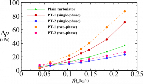
Figure 3 is dedicated for a comparison between the current results and those of references [29, 30] experiment. The two curves for each case, plain DPHE (green), DPHE with air injection (blue), DPHE built with solid, plain turbulator (red), are plotted for the purpose of validation only. The pressure gradient increases with the Reynolds number for all cases. However, unlike other situations where there is no turbulator, the turbulator's effect on flow changes quickly with the Reynolds number. The pressure losses are lower than those in the turbulator condition if two-phase is only considered inside the shell without a turbulator. The discrepancies between the given data are evident between the two approaches of investigation, especially for air injection case. This may be a result of the common experimental uncertainties that arise during measuring tasks. Another reason is that although the SST K-ω turbulence model is assumed to be adequate for our flows, there are still some deviations from reality. Another factor that contributes to better accuracy is two-phase modeling, in which the parameters of the flow as well as the flow conditions are greatly influenced by the void fraction. The pressure drops are calculated and presented in Figure 4 after combining that is related to the shell side (annulus) and that is within the helical tube (turbulator). All curves go higher if $\dot{m}_c$ increases owing to the high flow momentum. At very low flow rates shown in the figure (≤0.05 (kg/s)), the flow behaves differently regarding using the perforated turbulator (PT).
Figure 3. Pressure drops varying with Reynolds number in the annular. The current computational results with circles and solid lines are shown against the experimental results of the study [29] with deltas and dashed lines. The data of air injection case are from the study [30]’s experiment, where the air was blown from the annulus’ walls
That most likely may be explained by the same concept of preferring barriers causing swirls, such as perforated turbulators, in the turbulent regime while they act as twisted tapes in the laminar regime, such as plain turbulators. That also is confirmed by the amounts of gap between the data, where they are uneven and become more divergent as the flow rate increases. It is obvious that air causes more pressure than the water as seen through the profiles of orange and pink dashed lines than those represent water with red and blue solid lines. As a result, single-phase flows are more advantageous from a hydraulic standpoint, and using a turbulator with a flow rate of 0.0063 (kg/s) (PT-2 example) is also more affordable than using a solid, plain turbulator itself and 10% of the $\dot{m}_c$ case, or PT-1. In fact, the scenario of PT-2 (single phase) performs the best in terms of pressure losses, as shown by the blue solid line, because the flow enters the helical tube and helps its pressure to eliminate.
Figure 4. Current computational pressure drops with respect to mass flow rate of cold water ($\dot{m}_c$) inside a helical tube-based annulus with and without in-line horizontal perforations (PT) discharging either a single-phase water flow or two-phase bubbly flow
The Δp of PT-1 (two-phase) case is relatively the worst that significantly surpasses others and even that of the solid, plain turbulator (green curve).
6.2 Heat transfer rates
It can be seen from Figure 5 that all heat exchanger configurations work with higher heat transfer rates than that of solid, helical tube alone. There is significant increase in heat transfer between those of single-phase fluid entering both the shell and helical tube and those of other heat transfer treatments. When the flow is split into 10% $\dot{m}_c$ (PT-1) and enters the turbulator, it causes more heat transfer process. The quantity of heat transfer can be improved by pumping air into the cold fluid flow, however not as significantly as mixing the cold fluid flow itself by using some small jets. Air injection case can enhance the heat transfer better than depending on the solid turbulator alone, since the bubbles tend to gather upside and make some turbulence that can help promoting more heat transfer. Nevertheless, air is less in density and heat capacity making it undesired for two-liquid heat transfer process except for generating bubbles.
Figure 5. The heat transfer rate ($\dot{Q}$) calculated by Eq. (1) with respect to mass flow rate of cold water ($\dot{m}_c$) inside a helical-tube-based annulus with and without in-line horizontal perforations (PT) discharging either a single-phase water flow or two-phase bubbly flow
6.3 Overall heat transfer coefficient
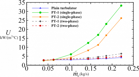
In Figure 6, the trend of improving the thermal performance due to perforated turbulator injecting a single-phase fluid is manifested again. The percentage increase is about 700% for case PT-1 (single phase) against that of solid, plain turbulator case. It is still of great interest that injection 10% of the mass flow rate of secondary fluid can enhance the thermal performance higher than it would if the mass flow rate was constant. The heat transfer changes remarkably with the mass flow rate for PT-1 and PT-2 cases of single-phase fluid. The black and red dashed lines appearing in the figure are for the two-phase injected fluid. They give an indication that the performance of PT-1 and PT-2 cases for two-phase fluid is still greater than that of the solid, plain turbulator with 52% for PT-1 and 17% for PT-2 approximately.
Figure 6. The overall heat transfer coefficient (U) defined by Eq. (2) with respect to mass flow rate of cold water ($\dot{m}_c$) inside a helical-tube-based annulus with and without in-line horizontal perforations (PT) discharging either a single-phase water flow or two-phase bubbly flow
Figure 7. The exergy destruction rate ($\dot{W}$) calculated by Eq. (5) with respect to mass flow rate of cold water ($\dot{m}_c$) inside a helical-tube-based annulus with and without in-line horizontal perforations (PT) discharging either a single-phase water flow or two-phase bubbly flow
6.4 Exergy calculation
The power lost due to the additional obstacles can be compensated by flowing more cold water inside the outer pipe. From design standpoint, the new arrangement adds more costs to the original heat exchanger, and the benefits should worth the change, thus the performance factor is usually used [9, 16, 24]. The quantity of exergy destruction rate, which gives an indication of how much the entropy increases with respect to its surroundings, is plotted in Figure 7 for the five cases of current interest. It has been determined from Figure 7 that the process of air injection blown from the small injectors appears to be more affordable than the cases of plain turbulator as well as PT-1 and PT-2 for single phase flow. While $\dot{W}$ of PT-1 and PT-2 with the single phase is higher than that of the turbulator alone, those for PT-1 and PT-2 with the two phase flows are the lowest. That means the irreversibilities caused by the turbulator and its injected fluid can be reduced if the air is introduced instead of the secondary fluid itself.
6.5 Oscillatory motion
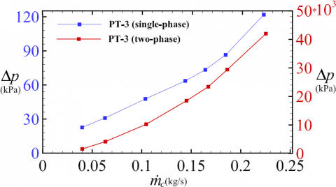
Figure 8. The computational pressure drops inside both the annulus and perforated turbulator (PT) exhibiting fluid injection with an oscillation for both water, PT-3 (single-phase) plotted on the left with blue curve, and mixture, PT-3 (two-phase) plotted on the right with red curve
Figure 9. The overall heat transfer coefficient ( ) defined by Eq. (2) for four cases named at the legend. The highest thermal performance is reached by injecting a fluid through small holes of the turbulator with oscillations
The injected fluid, water or air, is supposed to flow in the entire helical tube with a temporally constant pressure and steady state mass flow rate at the entrance. The flow starts at a high speed and gradually misses its momentum until it reaches the helical tube end. In the same setting, the outlet pressure is assumed constant and opens to the atmosphere. In the unsteady case, or PT-3, with amplitude Λ and frequency ω, the pressure fluctuates at the outflow around an equilibrium value (p0) of 101325 (Pa). In Figure 8, the pressure losses are comparatively doubled in the case of single phase and climb to big values when the air is introduced. Note that the oscillation is only for the turbulator flow, and the pressure losses in Figure 8 are for both annulus and turbulator flows. This should be taken into consideration before looking for thermal performance improvements. The flow becomes bidirectional due to oscillations in the helical tube, and thus the flow experiences bi-waves from both directions. These waves elevate the friction which leads to high flow losses.
There is a big amount of improvement in terms of overall heat transfer coefficient with approximately 1000% if the turbulator's flow of single phase oscillates (PT-3 case) with Λ = 5 (Pa) and ω =10 (rad/s). That is obvious in Figure 9, where $\dot{m}_c$ is for the annulus fluid while $\dot{m}=\Lambda(\omega t)$ is for the turbulator fluid which is unsteady. The second effective technique is PT-3 (two-phase) that shows high values of U compared to PT-1 (single phase) and solid, plain turbulator cases, although PT-1 showed the best performance of all previous tests.
6.6 Temperature and velocity distribution
The temperature distribution depicted in Figure 10 reveals some of the cooling process in the heat exchanger with perforated turbulator. The first part (a) exhibits temperature contour for the plain heat exchanger, and that of the second part (b) is for PT-1 with single phase fluid. When the hot water inlet temperature is 50℃, its outlet temperature can reach 20℃ if the turbulator flow is injected with relatively high velocity. This evokes other desires like make more holes around the helical tube to lower the exit temperature further. For plain DPHE, it is known that the flow experiences some residence-time delay since the two fluids are in counterflow directions. This flow gains even more additional time for heat transfer if the perforated tube is used with efficient obstructions from the tube itself and from the injected flows.
Figure 11 also displays both geometries, plain and modified one with perforated turbulators. It shows the flow patterns in terms of velocities. It can be noted from the legends that the velocity becomes very high at the holes, and their magnitudes decline as the flow goes down of the heat exchanger. This can lead to more turbulence which mixes the fluid and delays its residence time to escape more heat. Last but not least, there are various options for how the flow inside the helical tube can be driven, such as using the opposite side (hot water side entrance) as an inlet. In the latter case, turbulence can be doubled up, which improves thermal performance even further.
Figure 10. Temperature contours of both plain and perforated DPHE for single phase fluid (PT-1 case) when $\dot{m}_c$ = 0.22 (m/s), $\dot{m}_t=10 \% \dot{m}_c$. The planes are between z = 0.325 and 0.45 (m) in length, and x represents the transverse direction. The inlet cold water is 10℃ while the inlet hot water is 50℃, and the temperature gradient changes rapidly in the perforated DPHE
6.7 Heat exchanger effectiveness
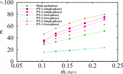
The effectiveness defined by Eq. (3) is plotted in Figure 12 for the highest flow rates tested in this study. The oscillatory flow, case PT-3 (single phase), achieves a percentage gain of 55% in comparison to the plain and other flow considerations. The ratio $\mathrm{c}=c_{\min } / C_{\max }$ was calculated taking into account that it is a variable. It is shown that the most dominated case is that related to the single phase flow, whether is it steady or unsteady. Not only the effectiveness increases, but also the NTU for the single phase fluid flow. In contrast, the two-phase flows with steady conditions are not beneficial, compared to others including the plain turbulator case. The air injection appears to be more effective on the performance when the flow is oscillating.
Figure 11. Velocity contours of both plain and perforated DPHE for single phase fluid (PT-1 case) when $\dot{m}_c$ = 0.22 (m/s), $\dot{m}_t=10 \% \dot{m}_c$. The planes are between z=0.325 and 0.45 (m) in length, and x represents the transverse direction. The inlet hot water mass flow rate is 0.094 (kg/s)
Figure 12. Heat exchanger effectiveness calculated with Eq. (3) for all cases investigated herein in terms of annulus mass flow rate ($\dot{m}_c$). It emphasizes the benefits of using perforated helical turbulator in DPHE with and without employing an oscillatory flow, especially that divides the secondary flow into annulus and 10% turbulator quantities
In earlier studies, helical turbulators were found to have the ultimate effect on the double pipe heat exchanger's performance. This study focuses on a new flow arrangement that creates holes around the turbulator to further increase the thermal effectiveness. These perforations in the helical tube bring more benefits to the plain turbulator. They can contain both steady and oscillatory flows, which will result in more disturbances, and they can produce vortices in a variety of directions. Despite the fact that it allows for more modifications in place, size, or fluid type, this kind of configuration is not found in the literature.
It is possible to divide the annular fluid into two amounts ensuring supplying the helical tube. The most successful modification is discovered to be the same fluid being injected through the perforations at different flow rate percentages. There has been a 600% increase in the overall heat transfer coefficient and a 45% improvement in the effectiveness with respect to those of the plain turbulator. The pressure loss, however, has also been doubled to 100%. The fluid may be combined with air in an effort to create additional turbulence. To give results that are meaningful, it must be blown at high pressure or pumped as an oscillatory flow. Although the oscillating flow has a big influence on heat transfer, its flow losses are quite expensive. If the turbulator does not exist, the same original flow amounts can be supplied, or additional flow quantities can be added to the perforated turbulator for good outcomes. It may be even better in the future to use different perforations with varying positions or to add more perforations all around the helical tube.
The authors would like to acknowledge the University of Kerbala (UoK) (the Iraqi Ministry of Higher Education and Scientific Research) for providing a financial support during this research.
|
A |
Total heat transfer area in mm2 |
|
c |
Ratio between $c_{\min }$ and $c_{\max }$ |
|
D |
Annulus diameter in mm |
|
d |
Inner pipe diameter in mm |
|
e |
Cross-section diameter of the helical tube in mm |
|
L |
Heat exchanger whole length in mm |
|
p |
Pressure in Pa |
|
Q |
The rate of heat transfer in kW |
|
Re |
Reynolds number |
|
t |
Time of oscillation in seconds |
|
T |
Static temperature in ℃ |
|
$\dot{Q}$ |
Heat transfer rate |
|
U |
Overall heat transfer coefficient in kW/$\mathrm{m}^2$. ℃ |
|
$\dot{W}$ |
Exergy destruction rate kW |
|
v |
Velocity magnitude in m/s |
|
x |
Transverse coordinate in mm |
|
z |
Axial coordinate in mm |
|
Greek symbols |
|
|
$\alpha$ |
Void fraction |
|
$\Delta p$ |
Pressure drop calculated for the outer pipe only in kPa |
|
$\epsilon$ |
Heat exchanger effectiveness |
|
$\Lambda$ |
Oscillation amplitude of mass flow rate in kg/s |
|
$\mu$ |
Dynamic viscosity in Pa.s |
|
$\omega$ |
Oscillation frequency in rad/s |
|
$\rho$ |
Fluid density in kg/m3 |
|
Subscripts |
|
|
$A_o$ |
Cross-sectional area of annulus in mm2 |
|
$A_{\ell}$ |
Cross-sectional area of liquid phase in mm2 |
|
$A_g$ |
Cross-sectional area of gas phase in mm2 |
|
$C_p$ |
Specific heat capacity in j/g ℃ |
|
$C_{\min }$ |
Minimum of specific heat capacity in j/g ℃ |
|
$D_e$ |
Equivalent diameter in mm |
|
$d_t$ |
Helical tube diameter in mm |
|
$E \dot{x_d}$ |
Exergy destruction rate in kW |
|
$G_c$ |
Parameter appears in Reynolds number in kg/m2s |
|
$\dot{ma}$ |
Air mass flow rate in kg/s |
|
$\dot{mc}$ |
Cold water mass flow rate in kg/s |
|
$\dot{mh}$ |
Hot water mass flow rate in kg/s |
|
$\dot{mt}$ |
Turbulator’s fluid mass flow rate in kg/s |
|
$p_0$ |
Atmospheric pressure in Pa |
|
$Q_{act}$ |
Actual Heat transfer rate in kW |
|
$Q_{\max }$ |
Maximum Heat transfer rate in kW |
|
$T_c$ |
Cold water temperature in ℃ |
|
$T_h$ |
Hot water temperature in ℃ |
|
$T_{\max }$ |
Maximum temperature in ℃ |
|
$\rho_g$ |
Gas density in kg/m3 |
|
$\rho_{\ell}$ |
Liquid density in kg/m3 |
|
Acronyms |
|
|
DPHE |
Double pipe heat exchanger |
|
DPM |
Discrete phase method |
|
HE |
Heat exchanger |
|
NTU |
Number of transfer units |
|
PT-1 |
Perforated turbulator with $\dot{m}=10 \% \dot{m_c}(\mathrm{~kg} / \mathrm{s})$ |
|
PT-2 |
Perforated turbulator with $\dot{m}=0.0063(\mathrm{~kg} / \mathrm{s})$ |
|
PT-3 |
Perforated turbulator with$\dot{m}=\Lambda(\omega t)(\mathrm{kg} / \mathrm{s})$ |
[1] Katkade, S.D., Barjibhe, R.B. (2018). A review on heat transfer enhancement with turbulators. In AIP Conference Proceedings, 2018(1): 020007. https://doi.org/10.1063/1.5058244
[2] Omidi, M., Farhadi, M., Jafari, M. (2017). A comprehensive review on double pipe heat exchangers. Applied Thermal Engineering, 110: 1075-1090. https://doi.org/10.1016/j.applthermaleng.2016.09.027
[3] Naphon, P. (2006). Effect of coil-wire insert on heat transfer enhancement and pressure drop of the horizontal concentric tubes. International Communications in Heat and Mass Transfer, 33(6): 753-763. https://doi.org/10.1016/j.icheatmasstransfer.2006.01.020
[4] Promvonge, P. (2008). Thermal augmentation in circular tube with twisted tape and wire coil turbulators. Energy Conversion and Management, 49(11): 2949-2955. https://doi.org/10.1016/j.enconman.2008.06.022
[5] Wang, Q., Chen, G., Chen, Q., Zeng, M. (2010). Review of improvements on shell-and-tube heat exchangers with helical baffles. Heat Transfer Engineering, 31(10): 836-853. https://doi.org/10.1080/01457630903547602
[6] Dincer, I., Zamfirescu, C. (2014). Chapter 1 - Fundamentals of thermodynamics. Advanced Power Generation Systems, pp. 1-53. https://doi.org/10.1016/B978-0-12-383860-5.00001-8
[7] Liu, S., Sakr, M. (2013). A comprehensive review on passive heat transfer enhancements in pipe exchangers. Renewable and Sustainable Energy Reviews, 19: 64-81. https://doi.org/10.1016/j.rser.2012.11.021
[8] Zohir, A.E., Habib, M.A., Nemitallah, M.A. (2015). Heat transfer characteristics in a double-pipe heat exchanger equipped with coiled circular wires. Experimental Heat Transfer, 28(6): 531-545. https://doi.org/10.1080/08916152.2014.915271
[9] Sheikholeslami, M., Gorji-Bandpy, M., Ganji, D.D. (2015). Review of heat transfer enhancement methods: Focus on passive methods using swirl flow devices. Renewable and Sustainable Energy Reviews, 49: 444-469. https://doi.org/10.1016/j.rser.2015.04.113
[10] San, J.Y., Huang, W.C., Chen, C.A. (2015). Experimental investigation on heat transfer and fluid friction correlations for circular tubes with coiled-wire inserts. International Communications in Heat and Mass Transfer, 65: 8-14. https://doi.org/10.1016/j.icheatmasstransfer.2015.04.008
[11] Sharafeldeen, M.A., Berbish, N.S., Moawed, M.A., Ali, R.K. (2017). Experimental investigation of heat transfer and pressure drop of turbulent flow inside tube with inserted helical coils. Heat and Mass Transfer, 53: 1265-1276. https://doi.org/10.1007/s00231-016-1897-z
[12] Suri, A.R.S., Kumar, A., Maithani, R. (2018). Convective heat transfer enhancement techniques of heat exchanger tubes: A review. International Journal of Ambient Energy, 39(7): 649-670. https://doi.org/10.1080/01430750.2017.1324816
[13] Panahi, D., Zamzamian, K. (2017). Heat transfer enhancement of shell-and-coiled tube heat exchanger utilizing helical wire turbulator. Applied Thermal Engineering, 115: 607-615. https://doi.org/10.1016/j.applthermaleng.2016.12.128
[14] Pérez-García, J., García, A., Herrero-Martín, R., Solano, J.P. (2018). Experimental correlations on critical Reynolds numbers and friction factor in tubes with wire-coil inserts in laminar, transitional and low turbulent flow regimes. Experimental Thermal and Fluid Science, 91: 64-79. https://doi.org/10.1016/j.expthermflusci.2017.10.003
[15] Maithani, R., Kumar, A. (2020). Effect of helical perforated twisted tape parameters on thermal and hydrodynamic performance in heat exchanger circular tube. Heat and Mass Transfer, 56(2): 507-519. https://doi.org/10.1007/s00231-019-02716-9
[16] Sikandar, M.U. (2019). Design of helical coil heat exchanger for a mini powerplant. International Journal of Scientific & Engineering Research, 10: 303-313.
[17] Bhattacharyya, S., Paul, A.R. (2021). The effect of circular hole spring tape on the turbulent heat transfer and entropy analysis in a heat exchanger tube: An experimental study. Experimental Heat Transfer, 34(6): 493-512. https://doi.org/10.1080/08916152.2020.1787560
[18] Khorasani, S., Dadvand, A. (2017). Effect of air bubble injection on the performance of a horizontal helical shell and coiled tube heat exchanger: An experimental study. Applied Thermal Engineering, 111: 676-683. https://doi.org/10.1016/j.applthermaleng.2016.09.101
[19] El-Said, E.M., Abou Alsood, M.M. (2018). Experimental investigation of air injection effect on the performance of horizontal shell and multi-tube heat exchanger with baffles. Applied Thermal Engineering, 134: 238-247. https://doi.org/10.1016/j.applthermaleng.2018.02.001
[20] Heyhat, M.M., Abdi, A., Jafarzad, A. (2018). Performance evaluation and exergy analysis of a double pipe heat exchanger under air bubble injection. Applied Thermal Engineering, 143: 582-593. https://doi.org/10.1016/j.applthermaleng.2018.07.129
[21] Pourhedayat, S., Sadighi Dizaji, H., Jafarmadar, S. (2019). Thermal-exergetic behavior of a vertical double-tube heat exchanger with bubble injection. Experimental Heat Transfer, 32(5): 455-468. https://doi.org/10.1080/08916152.2018.1540504
[22] Khorasani, S., Moosavi, A., Dadvand, A., Hashemian, M. (2019). A comprehensive second law analysis of coil side air injection in the shell and coiled tube heat exchanger: An experimental study. Applied Thermal Engineering, 150: 80-87. https://doi.org/10.1016/j.applthermaleng.2018.12.163
[23] Sinaga, N., Nisar, K.S., Kaood, A. (2021). Second law efficiency analysis of air injection into inner tube of double tube heat exchanger. Alexandria Engineering Journal, 60(1): 1465-1476. https://doi.org/10.1016/j.aej.2020.10.064
[24] Ghashim, S.L., Flayh, A.M. (2021). Experimental investigation of heat transfer enhancement in heat exchanger due to air bubbles injection. Journal of King Saud University-Engineering Sciences, 33(7): 517-524. https://doi.org/10.1016/j.jksues.2020.06.006
[25] Moria, H. (2021). Compound usage of twisted tape turbulator and air injection for heat transfer augmentation in a vertical straight tube with upward stream. Case Studies in Thermal Engineering, 25: 100854. https://doi.org/10.1016/j.csite.2021.100854
[26] Goh, L.H.K., Hung, Y.M., Chen, G.M., Tso, C.P. (2021). Entropy generation analysis of turbulent convection in a heat exchanger with self-rotating turbulator inserts. International Journal of Thermal Sciences, 160: 106652. https://doi.org/10.1016/j.ijthermalsci.2020.106652
[27] Khalil, E.E., Hwary, A., AboHedaima, S., ElShabrawy, M. (2021). Numerical Investigations of Heat Transfer enhancement in double pipe heat exchanger using twisted tape insert. In AIAA Scitech 2021 Forum, p. 1923. https://doi.org/10.2514/6.2021-1923
[28] Santos, H., Li, W., Kukulka, D. (2023). Numerical study of thermal-hydraulic performance improvement of enhanced surface tubes. Heat Transfer Engineering, 44(2): 103-124. https://doi.org/10.1080/01457632.2022.2034082
[29] Andrzejczyk, R., Muszynski, T., Kozak, P. (2019). Experimental investigation of heat transfer enhancement in straight and U-bend double-pipe heat exchanger with wire insert. Chemical Engineering and Processing-Process Intensification, 136: 177-190. https://doi.org/10.1016/j.cep.2019.01.003
[30] Andrzejczyk, R., Muszynski, T., Kozak, P. (2021). Experimental and computational fluid dynamics studies on straight and U-bend double tube heat exchangers with active and passive enhancement methods. Heat Transfer Engineering, 42(3-4): 167-180. https://doi.org/10.1080/01457632.2019.1699279
[31] Mohapatra, T., Padhi, B.N., Sahoo, S.S. (2019). Analytical investigation and performance optimization of a three fluid heat exchanger with helical coil insertion for simultaneous space heating and water heating. Heat and Mass Transfer, 55(6): 1723-1740. https://doi.org/10.1007/s00231-018-02545-2
[32] Akpinar, E.K. (2006). Evaluation of heat transfer and exergy loss in a concentric double pipe exchanger equipped with helical wires. Energy Conversion and Management, 47(18-19): 3473-3486. https://doi.org/10.1016/j.enconman.2005.12.014
[33] Dincer, I., Zamfirescu, C. (2014). Chapter 1 - Fundamentals of thermodynamics. Advanced Power Generation Systems, pp. 1-53. https://doi.org/10.1016/B978-0-12-383860-5.00001-8
[34] Ghajar, A.J. (2020). Two-phase gas-liquid flow in pipes with different orientations. Springer International Publishing. https://doi.org/ 10.1007/978-3-030-41626-3