Evgeniy N. Neverov* | Igor A. Korotkiy| Pavel S. Korotkih| Maksim Y. Mokrushin
© 2022 IIETA. This article is published by IIETA and is licensed under the CC BY 4.0 license (http://creativecommons.org/licenses/by/4.0/).
OPEN ACCESS
Refrigerating machines are used in many areas to produce artificial cold. In the course of its operation, each refrigeration unit generates a lot of heat by compressing the refrigerant, which is not used in any way in the future, and during condensation is released into the environment in the form of water vapor. The use of chlorine-containing refrigerants destroys the ozone layer. To reduce environmental damage, a water reuse system was created and a technology for using low-temperature heat that is released during the operation of the refrigeration machine was developed. This paper offers various design solutions aimed at the comprehensive modernization of the cooling system of the ice palace "Puck" in Sochi to reduce its impact on the environment. In the course of the research, a refrigeration unit was developed allowing utilization, accumulation, and channeling of condensation heat for the secondary use of thermal energy by other engineering systems at the facility, thereby reducing emissions of harmful substances into the Earth's atmosphere and increasing the technological capabilities of cooling. Methods that allow making the necessary calculations and selecting equipment for the implementation of the developed systems on ice arenas are also proposed.
coolant, greenhouse effect, heat recovery, heat transfer, refrigeration machine
People normally use cold for their needs, but it's seldom understood that the use of artificial cold harms the planet and mainly manifests itself in the destruction of the ozone layer and the greenhouse effect.
For the operation of the refrigeration unit, a refrigerant is used, which is compressed in the compressor, cooled in the condenser, expanded in the throttle device, and evaporated in the evaporator. To get compressed gas, you have to deal with the release of a large amount of heat. Gas temperature after compression in the compressor can be in wide ranges and reach 210°C and more. The heat from freon is transferred to the heat carrier and due to heat exchange during condensation, water vapor is formed, which in turn is released into the Earth's atmosphere.
In addition to this, the main requirement today for refrigerants of any enterprise using artificial cold is their environmental friendliness. The transition to modern ozone-safe refrigerants is an important task in refrigeration technology to ensure a reduction in the level of pollution on the planet.
1.1 Object of study
This research proposes a project aimed at minimizing the negative impact of refrigeration units on the hot water environment through the use of waste heat from refrigeration units for hot water accumulation. The object of the study is the cooling system of the ice palace "Puck" in the city of Sochi.
In the course of the research, it was revealed that in many refrigeration units there is no technical solution for heat utilization, which leads to a decrease in their efficiency and an increase in harmful emissions during their operation.
The creation of a heat recovery system formed by refrigeration unit compressors is the basis of this development. Using the allocated heat, the efficiency of the refrigerating machine as a whole increases, and this also leads to a reduction in the load on the condenser of the refrigerating machine, which helps to reduce the greenhouse effect by reducing unnecessary emissions of thermal energy into the environment. Since the ice arena was designed for the Winter Olympic Games in Sochi, and its transfer to another region is impossible due to technical features, a problem arose with the operation of the arena in the summer season. The condensing temperature of the refrigeration unit is very high (around 60°C), which leads to a decrease in the efficiency of the refrigeration unit and sometimes to a stop. To ensure stable operation, it is required to spray air condensers with water during the summer period to reduce the condensing temperature, which leads to high costs of supplied water and deterioration of the heat exchange surface of the condensers. During the modernization, the goal was not only to increase the efficiency of the arena by reducing the load on the capacitors but also to comply with all modern standards and improve the environmental safety of the city of Sochi.
As a result of the design work, a technology for reusing water from ice chips and a condensation heat recovery system were developed. In the work, problems were studied and eliminated during the operation of the refrigeration unit of the ice arena in the summer.
The structure of the work reflects the analysis of the ice palace "Puck" and its problems in cold supply, provides design solutions, shows the schemes and the principle of operation of the modernized system of cold and water supply based on the use of waste heat, and also discusses the results of modernization in the field environmental component.
The cost of compression requires a lot of energy, and the main way to get it is through thermal power plants. In the process of obtaining energy, a lot of carbon dioxide is released, which increases its concentration in the atmosphere. The release of greenhouse gases into the environment, such as carbon dioxide, methane, or water vapor, detains infrared radiation from the Earth, which can eventually lead to climatic changes on the Earth [1]. Freons used in refrigeration units lead to the destruction of the ozone layer of the Earth, as they contain chlorine, which, reacting under atmospheric conditions converts ozone into oxygen. Due to this, experts are beginning to ask questions related to the environmental situation. Everyone claims that it is necessary to take care of the surrounding world and create installations that will meet the standards but not every invention can be called environmentally safe.
Almost all refrigeration units produce a significant amount of heat during operation, which is often not used furthermore. However, the use of waste heat has a great energy potential, therefore, the creation of devices for the utilization of thermal energy is an important environmental and economic task, which is being researched in all developed countries of the world [2].
In recent years, technical solutions to reduce the impact on the environment have become increasingly relevant [3, 4]. At various industrial enterprises, new technologies are being introduced more and more often and methods aimed at the secondary use of energy resources are being improved. The use of refrigeration units with heat recovery is relevant, as the use of heat recovery allows reducing heat emissions into the atmosphere and at the same time utilizing this heat in other processes, which ultimately increases energy efficiency by reducing electricity consumption for these needs. It is important to note that heat recovery systems can be used not only on new installations but also implemented on those already put into operation [5].
Analyzing various ice arenas, we can conclude that despite the constant increase in the use of secondary heat from refrigeration machines its use is limited by the absence of permanent and energy-intensive consumers of low-grade heat near these sources. The use of recycling systems increases the cost of equipment, so all solutions are reduced to the most simplified use of heat, which is less efficient, or are used in large enterprises due to the high cost of implementation.
The disadvantage of the developed technologies is the lack of systems for returning water, which is formed during the melting of ice chips. For melting and heating water from ice chips, it is supposed to use the heat of condensation of refrigeration machines, which allows heating water with significant energy savings. The energy efficiency of ice arenas can be made up of several factors but reusing water and recovering waste heat brings the greatest economic benefit.
At the moment, careful management of water resources and water processing are also the future for many enterprises, in particular, for ice arenas, but there are few necessary systems and ready-made solutions on the market, or they do not affect the specifics of water consumption of ice fields [6].
As a result of research, computational and analytical work, at Kemerovo State University, together with the educational foundation "Talent and Success", a technology for heat recovery of condensation of ice arena cooling systems and air conditioning was developed. This development was based on a previously patented prototype of a steam compression refrigeration unit for efficient utilization of condensation heat, developed by the Department of Heat and Cooling Engineering.
The project is based on the development of working documentation, technical specifications of the customer, architectural and planning drawings, and in accordance with the rules and regulations for the design of new and reconstructed buildings, structures, and premises for various skating sports. Provisions of the code of rules apply to the design of ice fields with artificial frozen (ice) surfaces. As well implementation of the project provides for the development of design solutions for related sections on heating, ventilation and air conditioning, heating, water supply, and sewerage systems, considering regulations of fire alarm, power supply, and power electrical equipment, as well as the norms and rules in force in the territory of the Russian Federation.
During the design work, the cooling system of the entire ice palace was analyzed. Based on the results, a new schematic diagram of the cooling supply was developed, taking into account various factors and the possibility of introducing a heat recovery system [7, 8]. In the first section, several tasks were carried out on the introduction of a system for condensation heat utilization into the existing refrigeration unit of the ice arena and its subsequent use for technological needs. This section is aimed at creating joint work of heat recovery systems and water preparation for ice pouring. To implement the recycling system in the working unit, calculations were made according to the developed methodology. This includes the determination of the refrigerating machine operation cycles, its parameters, the flow rate, and the amount of heat that can be disposed of from the compressors to be used further on for the selection of heat exchangers. The selection is carried out according to the thermal load, based on the obtained calculations of the parameters of the refrigeration machine [9].
To fulfill the tasks of heat removal, AlfaLaval ACH112 plate three-circuit heat exchangers having two circuits for freon and one for water were chosen. Six heat exchangers, installed in three pieces on each refrigerating machine to ensure the removal of heat from different temperature levels are provided. To unify the equipment for all heat circuits, the same heat exchangers with a load of 200 kW were provided. The selected heat exchangers have the necessary heat exchange surface area and provide the required heat removal from refrigerating machines. To accumulate hot water and supply it to consumers, a battery tank is provided. Based on the calculation of the cycle, the amount of high-potential heat from one compressor of the refrigerating machine is Q = 80 kW. Then the amount of heat removed for one refrigeration machine of the arena's cooling system will be more than 320 kW, which will allow heating water in the volume of 15 m3 at 20°C (from 45°C to 65°C) in less than an hour.
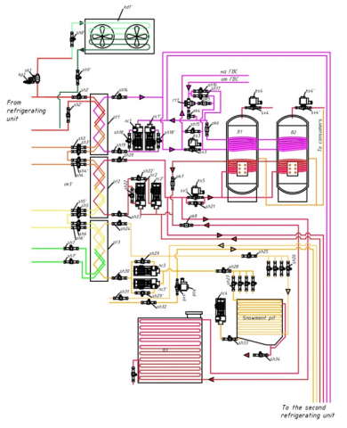
Based on the calculation, two battery tanks with a volume of 7.5 m3 each were engaged. According to the data obtained, it was concluded that the total accepted volume of 15 m3 tanks is sufficient to provide hot water to all consumers. The use of two tanks, instead of one, allows for a more stable and uniform supply of consumers. Figure 1 shows a diagram of the node of the heat recovery system, consisting of heat exchangers, battery tanks, pumps, and shut-off valves.
Removing medium-potential waste heat from the refrigerant in the heat exchanger for heat storage by heating water in three tanks will allow utilizing 212 kW of heat. Energy consumption spent on heating water for filling the ice cover will also be reduced. At the same time, the water is heated from 20°C to 40°C; this temperature range is optimal when mixing water supplied from the city water supply and allows one to achieve a minimum temperature difference between the two sources. The final water temperature when using mean potential heat is 40°C. Further heating to the temperature of pouring ice is carried out using high-potential heat.
To receive an excess of ethylene glycol, formed during liquid thermal expansion, it is necessary to provide expansion tanks. This equipment is necessary so that the properties of the coolant do not affect the efficiency of the disposal system and to prevent problems associated with the rupture of pipelines and other elements. In this installation, five expansion tanks with a volume of 1,500 liters were adopted.
To increase the energy and environmental efficiency of the ice arena, the developed project involves the reuse of water obtained as a result of ice cutting during the operation of ice filling combines for ice pouring.
In the course of the research, a drawing of the snowmelt pit was designed and a methodology was developed for its structural and thermal calculation, which allows the reuse of melt water in the technological cycle [10, 11]. This technique allows selecting auxiliary equipment and calculating the required design dimensions for the use of waste heat for heating the pit.
It is suggested to reuse the water obtained as a result of cutting ice during the operation of the resource facers. The resulting water will be used to pour ice cover.
The melting of ice chips occurs in the snowmelt pit with low-potential waste heat removed by the disposal system from refrigerating machines in the amount of 318 kW. This heat is enough to melt about three cubic meters of ice chips, then heat the resulting water to 20°C.
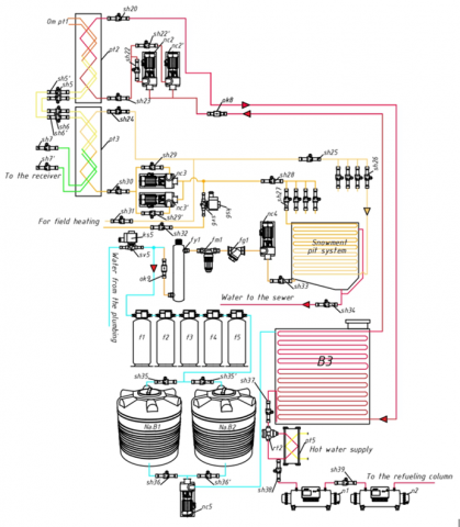
An additional filtration and water treatment system is also provided, shown in Figure 2, which will allow the reuse of meltwater in the technological cycle, significantly reducing the cost of wastewater disposal.
The principle of operation of the heat recovery and water reuse systems nodes according to the changes made is as follows: in the first of the three plate heat exchangers (pt1), high-potential heat is removed from the refrigeration machine compressors. The withdrawn high-potential heat from the freon coolant is fed through a ball valve (sh14) to a heat exchanger for hot water supply and sent to a heat point. When the solenoid (sv4) with a coil (ks4) is triggered, the heat is fed to the first section of the battery tanks (Ak.B1, Ak.B2) to heat the water. The remaining heat after heat exchange with the hot water heat exchanger through the temperature controller (rt1) is mixed with the flow of high-potential heat, passing through the check valve (ok5), excluding the reverse flow of the liquid.
The heat coming from the heat exchanger is fed to the tanks for heating, or sent through the check valve (ok4) bypassing them, depending on the temperature of the coolant. Regulation of the amount of incoming heat is carried out automatically using solenoids, but the scheme also provides ball valves (sh16, sh17), so it is possible to change the operating mode manually.
After heat exchange in the accumulator tanks, the coolant is fed through the check valve (ok6) by pumps (nc1 and nc1') back to the first stage heat exchanger (pt1) forming a closed independent circuit. Fresh water enters the tanks from the municipal water supply when the solenoid (sv5, sv5') is opened with a coil (ks5, ks5') at a temperature from 15 to 20 degrees.
Then it is heated up to 60 degrees and directed to heating, air conditioning system heating, and other consumers of thermal energy.
In the second heat exchanger (pt2), the average potential heat is removed. The reclaimed heat is sent through a ball valve (sh20) to the water treatment tank (B3), which is necessary for refueling ice-filling machines, and when the solenoid (sv6) is opened with a coil (ks6), the heat is used to heat water in the second section of the battery tanks (B1, B2). After heat exchange in all storage tanks, the coolant is fed back to the second stage heat exchanger through check valves (ok7, ok8) by pumps (nc2 and nc2'), forming a second closed independent circuit of heat circulation from the refrigerating machine to the storage tank.
The remaining low-potential heat is removed by a heat exchanger (pt3) and fed through a ball valve (sh31) to heat the ice field or supplies heat to the snowmelt pit through a ball valve (sh25). Low-potential heat is used to heat the snowmelt pit. The withdrawn heat from the freon enters through the inlet collector (sh26) to four coil heat exchangers in the snowmelt pit, where it is used to melt ice, cut from the field, and thrown into the pit by an ice filling machine, as well as for subsequent heating of this water. Having given up its heat, the coolant is pumped out through the outlet manifold (sh27) and the ball valve (sh28) using pumps (nc3 and nc3') and fed back to the intermediate heat exchanger, forming a third independent heat circulation circuit. Collectors can also be used to regulate the supply of the required amount of heat to the snowmelt pit by disconnecting one or more coil heat exchangers.
After the water in the pit reaches the temperature of about 20 degrees, it is pumped out of the pit by a pump (nc4) for filtration through a pipeline that is installed at 2/3 of the depth of the pit to exclude large ingress of contaminants that settle at the bottom. Before the main filtration, the water passes through coarse (fg1) and fine mechanical filters (fm1), as well as an ultraviolet filter (fy1). Then this water from the snowmelt pit is pumped through a check valve (ok9) to the central water supply pipeline. The latter supplies water when the solenoid (sv8) is opened with a coil (ks8), that is sent to the water treatment system through sedimentary ion exchange filters and a reverse osmosis unit (f1, f2, f3, f4, f5) installed sequentially, where it is completely cleaned. After filtration, the prepared water with a temperature of about 20 degrees through ball valves (sh35, sh35') enters two storage tanks (Na.B1, Na.B2) with a volume of 3 m3 each, creating the necessary water supply. From the storage tanks, when ball valves (sh36, sh36') are open, water is supplied by a pump (nc5) to a 3 m3 accumulator tank for prepared water (B3). There it is heated to the temperature of 60 degrees using a second heat circulation circuit from a refrigerating machine and can be used in the technological process for refueling resurfacers. If the water does not reach the required temperature, then, passing through the temperature controller (rt1), it is heated using a plate heat exchanger (pt5), in which the water is mixed with that from the hot water supply, or passes it if the water temperature is 60 degrees. Then it enters through a ball valve (sh38) into electric water heaters (n1, n2), which turn on and warm up the water to the required temperature, if it is less than 60 degrees, consuming electricity.
The issue of heating the ice field plate was not ignored, the low-potential heat circuit was embedded in the existing field heating system, thereby replacing hot heating. Field heating is designed to prevent freezing of the ground or to defrost the ice cover. Respectively, its use will take place during the absence of ice filling, thereby it will not affect the efficiency of melting ice chips in the snowmelt pit [12-16].
Based on the calculations carried out, design decisions were made, working documentation was developed for the device of heat condensation recovery systems and the necessary equipment was selected.
After that, considering all the changes and innovations, the equipment necessary for the implementation of the recycling system in the working installation was applied to the working drawings of the building layout. Namely, heat exchangers of the required capacity, battery tanks, water treatment tank, pumps, coarse and fine cleaning filters, UV filter, and shut-off valves. The plan for the compressor shop was finalized. These materials on the work done were included in the working documentation of the project as drawings and explanatory notes.
After the design, the hydraulic calculation of the new and modified circuits was performed, which made it possible to determine the pressure loss in the pipeline when moving the liquid over a distance, determine the optimal pipeline diameters and select the pump power. The data of these calculations make it possible to eliminate power shortage, plan a rational heat distribution device and save on materials for pipeline installation. Thus, the design and calculation of pipelines made it possible to optimize the heating system in terms of constructively and costs.
At the ventilation and air conditioning design stage, the selection of heat exchangers for the existing ventilation installations was carried out, which will contribute to improving the energy efficiency of the arena. This, in its turn, will lead to more rational consumption of electricity, allowing the heat to be disposed of from the ice field refrigerating machines to the entire building. This will lead to an improvement in the climate on the premises of the building. At the moment, fog formation periodically occurs on the ice field, resulting in visibility deterioration and a decrease in the climatic comfort of people visiting the arena. To solve the technical problem, 31 standard heat exchangers were selected. These devices will be placed in the basement, on the first, second, and third floors and introduced into the existing supply ventilation system according to technical specifications. Condensate drainage is provided from each implemented heat exchanger. Condensate can be collected in a drainage receiver for further use for technological purposes, which also leads to a reduction in water consumption and sewerage.
Also, according to the same method, one three-circuit heat exchanger was introduced into the scheme of the air conditioning system refrigeration machine to remove the heat of condensation and supply it to the heat point.
To increase the level of efficiency and mobility, optimize the production process, and free employees from performing labor-intensive operations manually, comprehensive refrigeration unit automation was carried out according to the decisions made to change its working conditions due to modernization.
The system provides for complex automation of ice field refrigerating machines and air conditioning systems, covering all tasks of control, management, and protection. In addition, the developed system allows a rational use of water at the facility, automatically filling the tanks with water from the snowmelt pit or water pipe, which allows for maintaining the accumulated heat constantly, thereby smoothing the unevenness of its supply to consumers. All the conditions for integration into the existing Siemens Desigo Insight 4.1 SCADA system were met.
The design and documentation development were carried out in accordance with the technical specification for the design, the current norms, rules, and State Standards of the Russian Federation.
The solutions included in the draft provide for the safe operation of the cooling system in compliance with the applicable intersectoral rules on labor protection during the operation of freon refrigeration units Intersectoral Labour Protection Rules POT RM 015-2000 [17-22].
The analysis of the state of the ice arena in Sochi and the study of the problems associated with its operation allowed us to propose grounds for the modernization of the ice complex cooling system.
In the course of the research, two methods were developed, one of which allows making calculations for the heat recovery system, while the other is applied to the thermal and constructive calculation of the snowmelt pit required capacity, depending on the available waste heat of the ice object.
The proposed modernization of the ice arena's cold supply is aimed at reducing the dependence of engineering and technological systems of facilities on urban heating and water supply systems. In addition, the developed technology will significantly reduce the thermal load on the condensers of the arena cooling system with the help of implemented intermediate heat exchangers thus eliminating the consumption of water, currently used for irrigation of air condensers to reduce condensation pressure and prevent an emergency shutdown of ice arena refrigerating machines. Also, the refrigerating machine is capable of completely or partially disconnecting the condenser from the system using a three-way valve, redirecting the entire heat flow. This allows the complete minimization of thermal energy emissions into the atmosphere. The refrigerating machine allows using three-way valves to switch heat exchangers to ensure different condensation temperatures in the condenser, thereby allowing adjustment of the installation cooling capacity as a whole.
The refrigerating machine runs on ozone-safe freons that do not contain chlorine atoms, which minimizes the potential of ODP and GWP. This installation is environmentally friendly, meets all modern requirements and standards, reduces the concentration of heat emissions, and helps to minimize the destruction of the ozone layer and the creation of the greenhouse effect [23]. The installation provides the facility not only with artificial cold but also allows using the released heat for various technological needs of the enterprise, which leads to significant savings in general. The project also covers the areas of wastewater disposal and sewerage through the accumulation and reuse of water. Application of these solutions leads to decreased water consumption and the available wastewater discharge emitted by such a water-intensive facility as the ice palace is significantly reduced.
As a result of the design work, a water reuse technology and a condensation heat recovery system were developed.
The received developments were included in the project for the ice arena "Puck", which involve the creation of joint work of heat recovery systems and water treatment for ice pouring.
Based on the calculations performed, design decisions were made and equipment was selected for the device of condensation heat recovery and reuse of water.
The removal of heat from refrigerating machines will fully ensure the heating of the snowmelt pit for melting ice, also allowing heat to accumulate by heating water in the installed accumulator tanks.
In addition to the listed measures aimed at improving the energy performance and resource intensity of ice arenas operation, the proposed systems were comprehensively automated and working documentation was created.
The designed cooling system ensures the utilization and transportation of heat to various consumers of thermal energy, which increases the energy efficiency of the refrigeration machine by removing heat from heat exchangers, and also reduces environmental pollution during operation.
The proposed technical solutions and methods can underlie the calculations and design of similar water recovery and reuse systems in other ice arenas.
The next steps on this topic are the study of various operating modes of the heat recovery system and the use of this system at other refrigeration and industrial facilities that have the opportunity of heat recovery.
The research is conducted as part of the comprehensive scientific and technical program of a complete innovative cycle "Development and implementation of a complex of technologies in the fields of exploration and extraction of minerals, ensuring of industrial safety, bioremediation, creation of new products of deep processing of coal raw materials with consecutive amelioration of ecological impact on the environment and risks to human life", approved by the Decree of the Government of the Russian Federation from 11.05.2022 №1144-r.
[1] Denisov-Vinsky, N.D. (2011). Heat compressor units. MegaPascal, 2: 8-16.
[2] Buchin, S., Smagin, S. (2010). Heat recovery systems in refrigeration units. The World of Climate, 62: 74-77.
[3] Piancastelli, L. (2022). Continuous, high efficiency defrosting of air-to-air heat pumps. Power Engineering and Engineering Thermophysics, 1(1): 2-7. https://doi.org/10.56578/peet010102
[4] Wang, L., Deng, S.H. (2022). Optimal operation control of composite ground source heat pump system. Power Eng. Eng Thermophys., 1(1): 64-75. https://doi.org/10.56578/peet010107
[5] Pinchuk, O.A., Kostko, A.F., Karavan, S.V. (2020). Complexate water treatment in small water circulation cooling systems. Bulletin of the International Academy of Cold, 3: 3-9. https://doi.org/10.17586/1606-4313-2020-19-3-3-9
[6] Neverov, E.N., Korotkiy, I.A., Mokrushin, M.Y., Prib, I.A., Goleshov, D.I. (2020). The project solution of the refrigeration machine scheme with the heat utilization of condensation. IOP Conference Series: Materials Science and Engineering, 2020(941): 012055-021055. http://dx.doi.org/10.1088/1757-899X/941/1/012055
[7] Korotkiy, I.A., Neverov, E.N., Korotkikh, P.S., Lonshakov, V.G. (2021). Developing a scheme for the utilization system of condensation heat from refrigerating machines to decrease the dependency of ice arena on municipal systems of heating and hot water supply. Journal of International Academy of Refrigeration, 2021(1): 34-39. https://doi.org/10.17586/1606-4313-2021-20-1-34-39
[8] Bondarevich, E., Kotsyurzhinskaya, N., Leskova, O., Mikhailova, L., Samoylenko, G. (2021). Monitoring the level of the air contamination by chemical elements impoundment in the snow melt of the snow blanket. Ecology and Industry of Russia, 25(8): 47-53. https://doi.org/10.18412/1816-0395-2021-8-47-53
[9] Korotkiy, I.A., Neverov, E.N., Prib, I.A., Mokrushin M.Yu., Goleshov, D.I., Lonshakov, V.G. (2020). Design solution to the scheme of a refrigerating machine with condensation heat utilization. Refrigerating Equipment, 109(6): 30-33. https://doi.org/10.17816/RF104056
[10] Institute of Public Buildings. (2007). Set of rules SP 31 112 2007. Part 3. Indoor ice arenas. System of regulatory documents in construction, Moscow.
[11] Gosstroy of Russia. (2003). Sanitary norms and rules SNiP 41 01 2003. Heating, ventilation and air conditioning. FGUP TSPP, Moscow.
[12] Caliskan, H., Lee, D., Hong, H. (2019). Enhanced thermodynamic assessments of the novel desiccant air cooling system for sustainable energy future. Journal of Cleaner Production, 211: 213-221. http://dx.doi.org/10.1016/j.jclepro.2018.11.174
[13] Danilov-Danilyan, V., Rosenthal, O. (2022). Methodology for reliable assessment of water quality. III. Assessment of water quality in conditions of variability of monitored indicators. Ecology and Industry of Russia, 26(5): 44-49. https://doi.org/10.18412/1816-0395-2022-5-44-49
[14] Israphilov, D.I., Mukhamatdinov, I.A. (2017). Ecology of refrigeration plants. Science Yesterday, Today, Tomorrow, 8(42): 58-62.
[15] Baranenko, А.V., Bukharin, N.N., Pekarev, V.I., Sakun, I.A., Timofeevsky, L.S. (1997). Refrigeration machines. Polytechnic, St. Petersburg.
[16] Shakirova, G.G. (2015). Recuperation of thermal energy removed by the compressor unit cooling system. Modern Innovations: Fundamental and Applied Research, 1(1): 6-7.
[17] Ministry of Regional Development of Russia. (2013). Set of rules SP 131.13330.2012. Construction climatology. Updated version of sanitary norms and rules SNiP 23 01 99. Ministry of Construction of Russia, Moscow.
[18] Guan, B., Liu, X., Wang, X., Zhang, T., Zhou, Z. (2022). Regeneration energy analysis on desiccant wheel system in curling arena for the Winter Olympics. Building and Environment, 214: 108960-108960. https://doi.org/10.1016/j.buildenv.2022.108960
[19] Tu, R., Li, J., Hwang, Y. (2020). Performance analysis of desiccant wheels assisted fresh air humidifiers in winter using natural gas boilers: Applied in cold and dry climate regions. International Journal of Refrigeration, 119: 24-36. http://dx.doi.org/10.1016/j.ijrefrig.2020.08.003
[20] Neverov, E.N., Korotky, I.A., Raschepkin, A.N., Ibragimov, M.I. (2020). Technological scheme for solid carbon dioxide production. Bulletin of the International Academy of Refrigeration, 1: 22-26. https://doi.org/10.17586/1606-4313-2020-19-1-22-26
[21] Belsky, Y.D. (2012). Modern society, Education and science. OOO "Consulting Company Ucom", Tambov, 16-17.
[22] Neverov, E.N., Korotkiy, I.A., Korotkih, P.S., Lifenceva, L.V. (2019). The method of carbon-dioxide recovery in fish-processing industry. IOP Conference Series: Earth and Environmental Science, 224: 012039-012039. http://dx.doi.org/10.1088/1755-1315/224/1/01203
[23] GOST 33662-2017. (2017). Refrigeration systems and heat pumps. Safety and environmental requirements. Standartinform, Moscow.