Jun Yao | Yuan Wang* | Di Feng
© 2022 IIETA. This article is published by IIETA and is licensed under the CC BY 4.0 license (http://creativecommons.org/licenses/by/4.0/).
OPEN ACCESS
In water-rich karst area, the lining structure of diversion tunnels is prone to cracking and gushing water problems under high water pressure, so water drainage design is often adopted for these diversion tunnels, that is, to drill holes on the lining structure and install drainage equipment to lower the external water pressure of the lining, therefore, accurately calculating the external water pressure of the lining is a very important work for the safety of the lining structure of tunnels. Based on the method of equivalent permeability coefficient, this paper regarded the drainage capacity of drainage equipment installed on the lining and the permeability of lining itself as a whole, and used the virtual equivalent permeability coefficient of the lining to describe it; then, this paper proposed a method for determining the equivalent permeability coefficient of lining and used it to analyze the drainage effect. Main conclusions of this paper are: 1) By designing tests for the drainage model of the tunnel drainage equipment and theoretically analyzing the seepage field of hydraulic tunnel, the equivalent permeability coefficient of the lining was determined and its accuracy was verified via numerical calculation; 2) Analytical calculation results and numerical simulation results of the tunnel were analyzed, and their conclusions about the effect of drainage capacity on the external water pressure of the lining were consistent; 3) The tunnel drainage design is an effective measure to reduce the external water pressure of the lining, the pressure reduction effect is obvious when k<1×10⁻⁶, and the groundwater level around the tunnel could be reduced at the same time. This paper provides a useful evidence for the design of high-pressure water diversion tunnels.
diversion tunnel, equivalent permeability coefficient, external water pressure of lining, volume of gushing water, drainage capacity, grouting circle, karst
In many countries and regions, the water diversion projects are an important measure to alleviate the shortage of water resource in water-deficient areas, in China, a large number of water diversion tunnels have been built for this purpose. A common situation encountered during tunnel construction is to pass through the water-rich karst area. When the tunnel runs through such area, the high permeability of surrounding rock would aggravate groundwater seepage, leading to the generation and expansion of rock cracks, even the penetration of rock mass. The large amount of groundwater gathering at the back of the tunnel lining can increase the external water pressure on the lining structure of the tunnel, and the large amount of gushing water can trigger engineering accidents such as water burst, lining cracking, and water seepage. Therefore, during tunnel construction and operation, the treatment of tunnel groundwater in karst area is one of the most important issues for the safety of tunnel structures [1].
To solve the high external water pressure of the lining structure, the design of diversion tunnels often adopts the principle of combining water plugging with drainage methods, that is, to set drainage equipment or drainage holes on the lining structure, so the stagnant water behind the lining could be discharged into the tunnels and the external water pressure of the lining could be reduced. Therefore, the drainage design of tunnels (namely the equivalent permeability of lining) is of great significance for reducing external water pressure and improving stress conditions of the lining structure [2], and the in-depth research about the influence of tunnel drainage design on the features of the seepage field of the tunnel and surrounding rock is worthy of the efforts [3].
As mentioned above, the water plugging and drainage design of tunnels is a primary means to solve the high external water pressure and large-volume gushing water of tunnel lining structure. Field scholars used model test and numerical simulation methods to analyze the law of using tunnel drainage design to reduce the external water pressure of the lining structure. For instance, Chen et al. [4] adopted the composite element method to build an explicit unit model for drainage holes which makes it feasible to easily mesh the complex geotechnical structure with a large number of drainage holes, and the computational mesh can remain unchanged and lower simulation difficulty when the number, position, and direction of drainages holes are adjusted. Xu and Chen [5] applied the composite element method to seepage analysis, in the paper, the drainage holes were regarded as a type of porous medium with large permeability, the permeability coefficient was used to describe the drainage function of drainage holes, and the drainage effect of drainage holes in the tunnels were simulated. Chen et al. [6] proposed a hierarchical composite element algorithm for drainage holes in rock mass. According to the variation principle, a control equation for solving the water potential of nodes was established, and the features of seepage in the composite unit elements containing drainage holes were analyzed. Cheng [7] used model test to prove that the lining pressure cannot be reduced under the totally enclosed condition, if drainage measures are adopted, the water pressure in the tunnel will be significantly reduced, and the external water pressure of the lining would drop linearly with the increase of the volume of discharged water. Feng et al. [8] performed numerical analysis on seepage, studied the distribution of uplift pressure and hydraulic gradient of dam sections and dam base, attained the relationship between the volume of inlet water and water pressure at the outlet of drainage holes, and proposed criteria for the flow control of drainage holes in the seepage control system at the Xiangjiaba Hydropower Station. Liu et al. [9] used the equivalent continuous medium model and the discrete fracture network model to calculate the seepage field in the study area and figured out the integrity, permeability and crack development of rocks, the research showed that the external water pressure was lower when the seepage control system was running and in this way the normal operation of the reservoir could be guaranteed. Xu et al. [10] used an iterative algorithm to determine the free surface, the author simplified the drainage hole as a straight line to simulate the function of the drainage hole and analyze the influence of drainage system on the seepage field. Zhao et al. [11] used numerical simulation and model test to study three waterproof and drainage optimization schemes, and analyzed the influence of different locations of drainage ditch on the external water pressure of the lining structure. In summary, field scholars mostly use numerical calculation and model test methods to study the drainage process of drainage holes and the variation laws of the seepage field, but few of them have concerned about the influence of the drainage capacity of drainage system on the external water pressure of the lining structure.
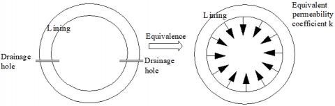
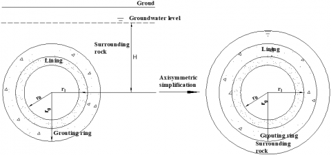
To figure out the influence of the drainage capacity of lining structure on external water pressure, in this paper, the drainage capacity of drainage equipment installed on the lining and the permeability of lining itself were taken as an integrated whole, and a virtual equivalent permeability coefficient of the lining was proposed to describe it, as shown in Figure 1. The equivalent permeability coefficient of lining was determined based on physical model experiment and analytical method. Through numerical simulation and analytical calculation, the reliability of the equivalent permeability coefficient of lining was verified, and the relationship between the equivalent permeability coefficient of lining and the external water pressure of lining was determined. At last, the law of the influence of drainage capacity on external water pressure was analyzed through numerical simulation.
Figure 1. Schematic diagram for determining the equivalent permeability coefficient of the lining structure of diversion tunnels
2.1 Design of tunnel drainage equipment
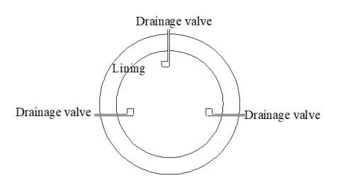
The drainage design of diversion tunnels is mainly to drill drainage holes on the lining or set professional drainage equipment to drain the water behind the tunnel lining into the tunnel, so as to reduce the external water pressure of the lining. Considering that there’re pressure water flowing in the diversion tunnel during operation period, the water in the tunnel might leak through the drainage holes, causing water resource waste, so in this paper, the pressure-reducing drainage valve has been chosen as the drainage equipment [12, 13]. The pressure-reducing drainage valve is a type of non-return valve that can discharge the water at the back of the lining into the tunnel to avoid internal water seepage, so its drainage capacity (the volume of water discharged) has a great influence on the external water pressure of the lining. The pressure-reducing drainage valves need to be installed on the lining, see Figure 2. The drainage capacity of pressure-reducing drainage valves is directly related to the diameter of the drainage pipeline, the layout on the lining, and the size of external water pressure, usually, the calculation is quite complicated, but we can use the equivalent permeability coefficient of the concrete lining structure with the same water permeability and no drainage equipment to describe its drainage capacity [14]. Therefore, the permeability coefficient of the lining can be used to study the drainage and pressure-reducing performance of the drainage equipment.
Figure 2. Layout of drainage valves in the diversion tunnel
2.2 Tunnel drainage test
(1) Design of test structure
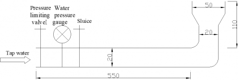
The test devices include the water pressure loading part, drainage pipe, and pressure-reducing valve, as shown in Figure 3. The drainage equipment was connected to tap water through high-pressure water pipe. The design water pressure was realized by the pressure-limiting valve. In the test, the water pressure was adjusted by the pressure-limiting valve to reach the water head required for the test to simulate the short-term unchanged state of groundwater level. A water pressure meter and a valve were installed at the water inlet of the drainage equipment, and a container was arranged at the water outlet to measure the volume of discharged water with an accuracy of 2.5.
During the test, the static test water pressure of tap water pipeline in the laboratory was 0.3MPa and water temperature was 21℃. To ensure the stability of water head during test, the test water pressure was chosen to be 0.23MPa~0.1MPa. When the design water pressure was reached by controlling the pressure-limiting valve, the drainage test started, and the design water pressure and corresponding volume of discharged water were recorded.
(2) Test process
At first, the drainage pipeline was assembled, the water inlet was connected with tap water in the laboratory through the high-pressure pipeline, a pressure-reducing valve and a water pressure meter were installed at the water inlet. Then, the tap water was turned on, the water flowed out from the end of the drainage pipeline for 2 min to discharge the air in the pipeline. After that, the pressure-limiting valve was adjusted, after the water pressure reached the design water pressure and stabilized, the water flow was kept running for 1 min; then, after the flow rate was stabilized, the flowing water pressure P at the pipe mouth and water volume Q of per unit time were recorded, the test results are listed in Table 1.
Figure 3. Drainage test devices
Table 1. Baseline test of water pressure and volume of the drainage equipment
|
No. |
Pressure at water inlet/MPa |
Volume of discharged water/cm3⋅s-1 |
|
1 |
0.23 |
77.5 |
|
2 |
0.20 |
70.0 |
|
3 |
0.18 |
64.9 |
|
4 |
0.16 |
61.6 |
|
5 |
0.14 |
56.9 |
|
6 |
0.1 |
52.6 |
(3) Test results and analysis
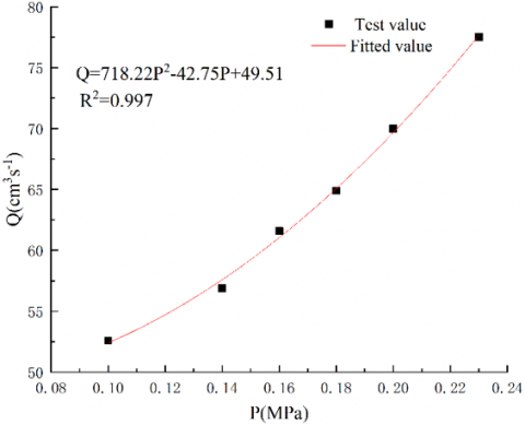
During the test, the pressure at the water inlet was fixed by adjusting the pressure-reducing valve, six feature values between 0.1MPa and 0.23MPa were selected, and the volume of water discharged from the drainage equipment was measured. The test data indicated that the higher the pressure at water inlet, the greater the volume of water discharged from the outlet. From 0.1MPa to 0.23MPa, the volume of discharged water increased by 47.4%. Higher water pressure and greater volume of discharged water can effectively reduce the external water pressure of the lining, which had met the requirement of tunnel drainage design.
Through the test, the relationship between design water pressure and the volume of discharged water could be attained. By fitting the data of water pressure and discharged water volume in Table 1, Formula 1 was attained. Then the error between the test data and the fitting values was analyzed, and the least square method was adopted for parameter estimation. After calculating the ratio of the regression sum of squares to the sum of squares of total deviations, it’s attained that R2=0.997, which indicated that the fitting accuracy was relatively high, and the fitting values were basically equal to the test values, as shown in Figure 4. Since the pressure of inlet water provided by tap water was limited, it’s difficult to simulate the volume of discharged water of the drainage equipment at higher water head, so this fitting formula can be used to predict the volume of discharged water under other inlet water pressure values.
$Q=-42.75 P+718.2 p^2+49.51$ (1)
where, Q is the volume of discharged water, its unit is cm3/s; p is the pressure at the water inlet, and its unit is MPa.
Figure 4. Relationship between water outlet pressure and volume of discharged water of the drainage equipment
2.3 Analytical calculation of tunnel seepage field
To analyze the tunnel seepage and calculate the gushing water volume and external water pressure of the lining, it’s assumed that: the cross-section of the tunnel is circular, the water heat H is far greater than the size of the tunnel, the surrounding rock of the tunnel is homogeneous in all directions and conforms to the equivalent continuous medium model, the Darcy theorem, and the continuity equation, Figure 5 gives a diagram of the analytical calculation. In the figure, k is the equivalent permeability coefficient of tunnel lining; kg is the permeability coefficient of grouting circle; km is the permeability coefficient of surrounding rock; ro is the inner diameter of tunnel; rl is the outer diameter at the back of the grouting circle; rg is the outer diameter of grouting circle; Φ1 is the total water head at the tunnel state; Φ2 is the total water head of surrounding rock at the back of the lining; H is the total water head of far field [15].
Figure 5. A diagram for simplifying the diversion tunnel as axially symmetric
(1) When the seepage velocity in the fractured rock mass is relatively small, the seepage exhibits as laminar flow, and it satisfies v=ki. According to the basic concepts of hydraulic gradient and seepage velocity, within the scope of the seepage field, there is [16]:
$\frac{d \phi}{d r_j}=\frac{Q}{2 \pi r_j k}$ (2)
where, ϕ=z+p/rw is the total water head; k is the elevation head; rw is the weight of per unit volume water; p is the pore water pressure; Q is the volume of gushing water in the tunnel; the direction of water flowing into the tunnel is positive, and the direction of water flowing out of the tunnel is negative.
(2) After tunnel excavation and before lining construction, there is:
$Q_1 / 2 \pi r=k_m d \phi_1 / d r$ (3)
Variables in Formula 3 were separated, $\frac{Q_1}{r} d r=2 \pi k_m d \phi_1$, according to the boundary conditions: r=r1, ϕ1=0; r=H, ϕ1=H [17].
Perform integral operation on both sides of Formula 3 to get:
$Q_1=\frac{2 \pi H k_m}{\ln \frac{H}{r_1}}$ (4)
(3) After the lining of the tunnel was built, the hydraulic field of the surrounding rock of the tunnel was changed from the unlined state ϕ1 to ϕ2, within the thickness range of the lining (r=r0∼r1), there is:
$Q_2 / 2 \pi r=k_l d \phi_{2 l} / d r$ (5)
The boundary conditions are r=r0, ϕ2l=0.
Variables in Formula 5 were separated, $Q_2 \frac{1}{r} d r=2 \pi k_l d \phi_{2 l}$, perform integral operation on both sides to get:
$\phi_{2 l}=\frac{Q_2}{2 \pi k_l} \ln \frac{r}{r_0}$ (6)
Within the grouting range (r=r1∼rg), there is:
$Q_2 / 2 \pi r=k_g d \phi_{2 g} / d r$ (7)
The boundary conditions are: $r=r_g, \phi_{2 g}=\phi_{2 g'}$.
Variables in Formula 7 were separated to get:
$Q_2 \frac{1}{r} d r=2 \pi k_{\mathrm{g}} d \phi_{2 g}$ (8)
Perform integral operation on both sides to get:
$\phi_{2 g}=\phi_{2 g^{\prime}}-\frac{Q_2}{2 \pi k_g} \ln \frac{r_g}{r_0}$ (9)
Within the range of surrounding rock (r=rg∼H), $Q_2 / 2 \pi r=k_m d \phi_{2 m} / d r$.
The boundary conditions are: r=H, ϕ2m=H, on the r=rg boundary, the boundary between grouting circle and surrounding rock, according to the continuity of hydraulic potential, there is $\phi_{2 g^{\prime}}=\phi_{2 m}$, and the hydraulic potential in the grouting circle is [18]:
$\phi_{2 g}=H-\frac{Q_2}{2 \pi k_m} \ln \frac{H}{r_g}-\frac{Q_2}{2 \pi k_g} \ln \frac{r_g}{r}$ (10)
According to the continuity equation, when r=r1, the flow rate at the back of the lining Q2 can be attained as follows:
$Q_2=\frac{2 \pi H k_m}{\ln \frac{H}{r_g}+\frac{k_m}{k_g} \ln \frac{r_g}{r_l}+\frac{k_m}{k_l} \ln \frac{r_l}{r_0}}$ (11)
Since Q2 can be determined by the drainage test, then the equivalent permeability coefficient k can be expressed as:
$k=\frac{k_m \ln \frac{r_l}{r_0}}{\frac{2 \pi H k_m}{Q_2}-\ln \frac{H}{r_g}-\frac{k_m}{k_g} \ln \frac{r_g}{r_r}}$ (12)
At this point, the Q2 and other related parameters could be determined according to the test, and the equivalent permeability coefficient k of the lining at different buried depths can be calculated.
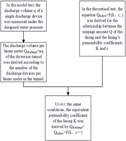
Based on model test and theoretical analysis, the equivalent permeability coefficient of the lining of diversion tunnels under different conditions was calculated, and the specific steps are:
(1) In the designed model test, pressure-reducing drainage valves of 1:1 ratio were fabricated, and the water discharge volume of each single valve was measured under the design water pressure, as shown in Figure 4; then, according to the layout of pressure-reducing drainage valves in the tunnel, the per unit time water discharge volume for each linear meter in the diversion tunnel was calculated, and the specific test process is introduced in Section 2.3.
Figure 6. Flow for determining the equivalent permeability coefficient of hydraulic tunnel lining
(2) In the theoretical analysis, based on simplified axisymmetric calculation model, it’s assumed that the groundwater flow conforms to the Darcy's law and the water flow continuity equation, then, according to the permeability coefficient of lining, the permeability coefficient of surrounding rock, the permeability coefficient of grouting circle, and the size of tunnel lining, the seepage volume and external water pressure of tunnel lining were derived, as detailed in Section 2.4.
(3) The water discharge volume of the tunnel measured in the model test was equal to the gushing water volume of the lining attained in theoretical analysis, then, the calculated permeability coefficient of lining was the equivalent permeability coefficient of lining of the set drainage system, the specific flow is shown in Figure 6 [19].
To verify the accuracy of the equivalent permeability coefficient of lining, the same diversion tunnel model was solved respectively by the analytical method and the numerical calculation method, then the external water pressure values of the lining were compared to judge the reliability of the equivalent permeability coefficient of lining.
Basic information of the diversion tunnel: the water head at the center of the tunnel is H=30 m; the diameter of drainage holes is 0.02m, there’re three drainage equipment on each cross-section, the permeability coefficient of surrounding rock km is shown in Table 2; the permeability coefficient of grouting circle is kg=1.0×10⁻⁶m/s; the lining is impermeable, and its equivalent thickness is 0.4 m; the equivalent inner diameter of lining is r0=6.7m; the equivalent outer diameter of lining is rl=8.4 m; the outer diameter of grouting circle rg=11.4 m.
A 2D seepage-stress coupling model was built in ABAQUS to simulate the excavation and grouting process. The model is 50 m wide and 60 m high; the buried depth of the tunnel is 30m and the tunnel diameter is 8.4m; the permeability coefficient of surrounding rock is given in Table 2; the permeability coefficient of grouting circle is 1.0×10⁻⁶m/s; the equivalent permeability coefficient is taken as the permeability coefficient of the lining; boundary water heads are added to both sides of the model; the groundwater level line is at the top of the model, the equivalent permeability coefficient of the lining calculated based on Formula 12 is shown in Table 2.
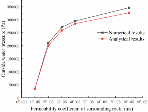
Table 2 compares the results of the external water pressure of lining calculated by the numerical calculation method and analytical calculation method. According to the table data, it’s known that, under the condition of different permeability coefficients of surrounding rock, as the permeability coefficient of surrounding rock increases, the equivalent permeability coefficient of lining decreases, the external water pressure of lining increases, the results of the external water pressure calculated by numerical calculation method and analytical calculation method are close, and the numerical calculation result is slightly larger, as shown in Figure 7, the error of the calculation results of the two methods is within 5%, which has verified the feasibility of the equivalent permeability coefficient method, and it also indicates that the equivalent permeability coefficient can describe the drainage process of drainage equipment. This equivalent permeability coefficient method can simplify the calculation process of the influence of drainage equipment on the seepage field and effectively calculate the external water pressure of the lining [20].
Table 2. Comparison of calculation results of different calculation methods
|
km(m⋅s-1) |
k(m⋅s-1) |
Numerical calculation result (Pa) |
Analytical calculation result (Pa) |
|
1×10⁻⁵ |
8.13e-6 |
3.591e4 |
3.47e4 |
|
2×10⁻⁵ |
1.41e-6 |
2.107e5 |
2.01e5 |
|
3×10⁻⁵ |
1.09e-6 |
2.711e5 |
2.58e5 |
|
4×10⁻⁵ |
9.91e-7 |
2.953e5 |
2.85e5 |
|
8×10⁻⁵ |
8.64e-07 |
3.463e5 |
3.268e5 |
Figure 7. Relationship between external water pressure of lining and permeability coefficient of surrounding rock
1. Through model test, this paper simulated the drainage equipment and the drainage process of tunnel lining under the design water pressure, calculated the volume of discharged water, figured out the relationship between the water pressure at the water inlet of the drainage equipment and the volume of water discharged from the outlet, and then predicted the water discharge volume of the tunnel under the action of design external water pressure.
2. Through theoretical analysis, this paper studied the seepage field of surrounding rock of hydraulic tunnel, derived the formulas of the external water pressure of the lining and the volume of gushing water, and analyzed the influence of the permeability coefficient of lining, permeability coefficient of surrounding rock and permeability coefficient of grouting circle on the external water pressure of the lining and the volume of gushing water.
3. This paper introduced the concept of equivalent permeability coefficient to analyze the influence of tunnel drainage process on the seepage field of the lining; combining drainage test and theoretical analysis, the paper derived the formula for determining the equivalent permeability coefficient, based on which the equivalent permeability coefficient of the lining could be solved quickly. After that, this paper combined numerical calculation method with analytical calculation method and verified the accuracy of the equivalent permeability coefficient.
This paper was supported by the Key Project of Natural Science Research Project of Higher Education Institutions in Anhui Province (Grant No.: KJ2019A0822).
[1] Xu, Z., Wang, X., Li, S., Gao, B., Shi, S., Xu, X. (2019). Parameter optimization for the thickness and hydraulic conductivity of tunnel lining and grouting rings. KSCE Journal of Civil Engineering, 23(6): 2772-2783. https://doi.org/10.1007/s12205-019-1509-9
[2] Liu, Y., Feng, Y., Xu, M., Zhang, Y., Long, H., Zhu, H. (2019). Effect of an incremental change in external water pressure on tunnel lining: a case study from the Tongxi karst tunnel. Natural Hazards, 98(2): 343-377. https://doi.org/10.1007/s11069-019-03692-3
[3] Wang, X., Li, S., Xu, Z., Hu, J., Pan, D., Xue, Y. (2019). Risk assessment of water inrush in karst tunnels excavation based on normal cloud model. Bulletin of Engineering Geology and the Environment, 78(5): 3783-3798. https://doi.org/10.1007/s10064-018-1294-6
[4] Chen, S., Xu, Q., Jing, H. (2004). Composite element method for seepage analysis of geotechnical structures with drainage hole array. Journal of Hydrodynamics, 16(3): 260-266. https://doi.org/10.1016/j.jfluidstructs.2003.09.001
[5] Xu, G.S., Chen, S.H. (2005). Study on the composite element method for modeling drainage holes. Journal of Hydrodynamics, 2: 214-220.
[6] Chen, S.H., Qin, N., Xu, G.S., Shahrour, I. (2010). Hierarchical algorithm of composite element containing drainage holes. International Journal for Numerical Methods in Biomedical Engineering, 26(12): 1856-1867. https://doi.org/10.1002/cnm.1271
[7] Cheng, Z. (2012). Study on water pressure characteristics of Xiamen Xiang'an subsea tunnel. Engineering Sciences, 14(11).
[8] Feng, S., Jiang, Z., Zhong, H., Zeng, X., Ding, P. (2017). Control criterion of water inrush for drainage hole in the base of xiangjiaba gravity dam. Shuili Xuebao/Journal of Hydraulic Engineering, 48(1): 21-30. https://doi.org/10.13243/j.cnki.slxb.20151357
[9] Liu, Z. J., Huang, Y., Zhou, D., Ge, H. (2017). Analysis of external water pressure for a tunnel in fractured rocks. Geofluids. https://doi.org/10.1155/2017/8618613
[10] Xu, Z., Liu, Y., Huang, J., Wen, L., Chai, J. (2019). Performance assessment of the complex seepage-control system at the Lu Dila hydropower station in China. International Journal of Geomechanics, 19(3): 05019001. https://doi.org/10.1061/(ASCE)GM.1943-5622.0001363
[11] Zhao, D., Fan, H., Jia, L., Song, Y. (2021). Research on waterproofing and drainage optimization scheme for karst tunnel lining in water-rich areas. Environmental Earth Sciences, 80(4): 1-18. https://doi.org/10.1007/s12665-021-09466-0
[12] Huang, F., Tan, Z., Wang, M., Wang, X. (2009). Analytical solutions for water inflow into an underwater tunnel and its application. Engineering Sciences, 11(7): 66-70. https://doi.org/10.1016/S1874-8651(10)60059-2
[13] Sharifzadeh, M., Karegar, S., Ghorbani, M. (2013). Influence of rock mass properties on tunnel inflow using hydromechanical numerical study. Arabian Journal of Geosciences, 6(1): 169-175. https://doi.org/10.1007/s12517-011-0320-9
[14] Huang, Y., Yu, Z., Zhou, Z. (2013). Simulating groundwater inflow in the underground tunnel with a coupled fracture-matrix model. Journal of Hydrologic Engineering, 18(11): 1557-1561. https://doi.org/10.1061/(ASCE)HE.1943-5584.0000455
[15] Zhao, X., Yang, X. (2019). Experimental study on water inflow characteristics of tunnel in the fault fracture zone. Arabian Journal of Geosciences, 12(13): 1-14. https://doi.org/10.1007/s12517-019-4561-3
[16] Zhou, J.Q., Liu, H.B., Li, C., He, X.L., Tang, H., Zhao, X.J. (2021). A semi-empirical model for water inflow into a tunnel in fractured-rock aquifers considering non-Darcian flow. Journal of Hydrology, 597: 126149. https://doi.org/10.1016/j.jhydrol.2021.126149
[17] Arjnoi, P., Jeong, J.H., Kim, C.Y., Park, K.H. (2009). Effect of drainage conditions on porewater pressure distributions and lining stresses in drained tunnels. Tunnelling and Underground Space Technology, 24(4): 376-389. https://doi.org/10.1016/j.tust.2008.10.006
[18] Hassani, A.N., Farhadian, H., Katibeh, H. (2018). A comparative study on evaluation of steady-state groundwater inflow into a circular shallow tunnel. Tunnelling and Underground Space Technology, 73: 15-25. https://doi.org/10.1016/j.tust.2017.11.019
[19] Barani, O.R., Khoei, A.R. (2014). 3D modeling of cohesive crack growth in partially saturated porous media: a parametric study. Engineering Fracture Mechanics, 124: 272-286. https://doi.org/10.1016/j.engfracmech.2014.04.016
[20] Zhao, J., Liu, W., Shen, J., Xu, M., Sasmito, A.P. (2022). A real-time monitoring temperature-dependent risk index for predicting mine water inrush from collapse columns through a coupled thermal–hydraulic-mechanical model. Journal of Hydrology, 607: 127565. https://doi.org/10.1016/j.jhydrol.2022.127565