Kawa Abdulghany Abdullah* | Ramzi Raphael Ibraheem Barwari
© 2022 IIETA. This article is published by IIETA and is licensed under the CC BY 4.0 license (http://creativecommons.org/licenses/by/4.0/).
OPEN ACCESS
The variable refrigerant flow (VRF) system is extensively utilized for the purpose of space cooling and heating in residential and commercial buildings. The VRF outdoor units are frequently placed on balconies of multi-storey buildings, and the aluminum louvers conceal them to keep the aesthetic architecture appearance. This type of installation will cause the thermal plume influence of the dissipated heat discharged from condensing units to cause high suction temperature, high energy consumption, and low coefficient of performance of the system. The numerical results showed that the discharged heat from condensing units will lead to rising thermal plume influence, causing greater suction temperatures for VRF outdoor units on top floors, even overriding the operating temperature range. It also shows that removing the inward louver in front of the discharge duct on each floor is an efficient method to deteriorate the thermal plume influence for VRF air conditioners and enhance the thermal efficiency of the entire system. For the proposed design, the average suction temperatures could be reduced by 8%, 15%, and 19% for VRF outdoor units for floors 10th, 11th, & 12th, respectively. This work aims to provide guidelines for the placement of VRF air conditioners in buildings in the designing stage.
CFD simulation, energy consumption, outdoor air temperature, thermal plume, VRF system
A variable Refrigerant Flow (VRF) air-conditioning system is a kind of recently mostly utilized system because of its flexibility and high energy efficiency in part-load operations compared with conventional central air-conditioning systems [1]. There is often more than one variable-speed compressor in a VRF air-conditioning system to be able to adjust the capacity by varying the frequency of the compressor to fit the variation of the thermal load. The indoor units in a VRF system can be separately controlled by changing the refrigerant flow rate to satisfy the heating or cooling needs in each space, so the VRF system is particularly suitable for the type of building with various functional spaces and complex load conditions, like market buildings and office buildings [2]. The VRF system transfers heat between an outdoor heat exchanger unit and multi-indoor units located within or close to the conditioned area through refrigerant copper piping placed in the building as shown in Figure 1 [3].
The main advantage of the VRF air conditioner compared to traditional air conditioning systems is their great response to instabilities in room load conditions. They use a direct current inverter to the compressor to sustain varying motor speeds and hence variable refrigerant flows instead of just performing on/off work. VRF air conditioners operate exclusively at the required rate, permitting substantial power savings at load necessities. Power savings of up to 55% are expected as compared with individual units. This even results in more significant management of the facility's indoor temperature by the facility's residents, as shown in Figure 2 [4]. VRF systems can be classified into two broad categories: heat pumps and heat recovery systems. In a heat pump (HP), a two-pipe system, the entire space should either be entire in heating or entire in cooling. Heat recovery (HR) systems can cool some areas while heating others; this is typically accomplished using a three-pipe configuration. These pipes consist of a suction gas pipe, a discharge gas pipe, and a liquid pipe. The additional third pipe enables the system to carry the waste thermal energy of an indoor unit (produced from the main mode, whether cooling or heating) to the rest of the system [5].
The performance of the VRF systems greatly depends on the suction temperature of the condensing units. However, the coefficient of performance of the VRF systems declines by approximately 3% when the condensing units’ suction temperature is increased by 1.0℃. Also, architectural restrictions permanently guide the placement of the outdoor units in the closed spaces on the building balconies. Disappearing the outdoor units in the building balconies with louvers significantly decreases the system's performance and creates a potential issue for the AC systems.
Figure 1. VRF systems with multiple indoor evaporator units
Figure 2. Components of VRF systems
With this secure installation space, the heat dissipated by the outdoor units is not well discharged to the environment, which raises the suction temperatures of the condensing units. This high suction temperature results in a significant deterioration in the performance of the VRF system, particularly for the units on the top floors. Occasionally, it results in the operational stoppage of the units. Consequently, appropriate and adequate ventilation space of the outdoor units with good organization of the outdoor units in the building balconies is the essential parameter for the performance and power consumption of the air conditioner units.
Hence, to analyze the temperature and airflow distribution of outdoor units, it is very essential to know the mechanism of the effect of thermal plume air for VRF condensing units in cooling mode. However, owing to the complexity of the system of practical engineering, the theoretical solution of the outdoor airflow condition is difficult to obtain. This paper aims to investigate the thermal plume flow distribution of air for layer-based VRF units by using (CFD) simulation to know whether outdoor units might cause high pressure or temperature problems or not [6]. In addition, an explanatory example of an actual VRF system is carried out in a 23-floor office building in Erbil city, and the influence of louver parameters on VRF condensing units is displayed. The suction temperature distributions are investigated to reveal the thermal plume influence caused by the dissipated heat from condensing units. In addition, it will cause a drop in cooling capacity, high energy consumption, and a low coefficient of performance of the system. The main objective of this research is to investigate the thermal plume influence to recommend the best location for the VRF outdoor units installed in multi- storey buildings.
Many researchers have studied the thermal environment and the improvement of the working temperature of VRF air conditioning systems. Chow and Lin [7] implement computer simulations using CFD software to analyze the performance of split air conditioners regarding the temperature upgrade of outdoor units placed in building re-entrant. It was seen that the CFD method is the proper approach to study the thermal plume influence on the efficiency of the air conditioner units that condition the various stories of the building. Furthermore, it was predicted that the suction temperature of condensing units would rise by approximately 7.0℃ for the upper stories of tall commercial buildings in China. Chow et al. [8] performed some analyses on various re-entrant layouts utilizing the CFD simulation methods with building energy evaluation samples. The results display no basis that the modern re-entrant layouts will have negative impacts compared to the traditional shapes. Chow et al. [9] revealed numerical approaches to investigate the influence of airflow features surrounding the outdoor units on the characteristics of the air conditioner. Two different airflow modes were analyzed. They mentioned that installing the condensing units like that by discharging the cooling air from outdoor units into the building air shaft, was the best way to prevent reverse flow phenomena. This was associated with the thermal plume formed by the exhausted hot air that will push airflow. Furthermore, it was indicated that the steady-state grid model fits well with the CFD technique results. They found that exhausting the condensing units' air into the building`s air shaft results in more reliable performance of the unit and consumes less electricity approximately % 10 in comparison with the state of placing the condensing units in a building re-entrant. Bojic et al. [10] predict the velocity vector and temperature distributions of an ascending thermal plume created by a recessed area in a 30-floor tall building utilizing the CFD approach. Then, creating the two depths of the building with five window-type air conditioners were analyzed for each floor. The results showed that the air volume flow rate and the temperature of the rising airflow in the recessed area are not seriously influenced by its width. A deeper recessed area results in a rise in the temperature of the airflow surrounding the condensing units and a drop in the temperature of the air surrounding the units. Xue [11] investigated numerical simulation of airflow and temperature distribution in an enclosed area of a 16-floor tall commercial building. It has been noticed that the space between the outdoor unit and the wall is a significant factor influencing temperature rise. To maintain a temperature increase of less than 10℃, a minimum distance of 7 m is required for a 16-floor tall building. Increasing the speed of the fans on outdoor units results in a greater temperature in the enclosed area due to the adverse effect on natural convection caused by the thermal plume influence. Pean and Yau [12] studied the influence of climate variability on a ducted type AC split unit in a commercial building located in Malaysia. According to the findings, each 1°C increase in ambient temperature reduces the system's total cooling capacity and energy efficiency ratio by 2%. Choi et al. [13] analyzed the increase in the working temperature of the condensing units with an increase in the environmental wind speed. The case of installing the outdoor units in the mechanical room was expected. They stated that the wind direction and wind speed significantly influence the thermal plume influence. It was also seen that the side wind results in an increase in working temperature by approximately 2°C and that frontal winds increase the temperature by approximately 6℃ for 40-storey buildings.
Avara and Daneshgar [14] investigated the effect of the distance between the two sidewalls of the condensing units on the suction temperature of the units utilizing CFD simulation. They suggested several good spaces between the AC condensing unit and the sidewall in various situations. In the matter of placing the condensing units on the roof, the influence of the height of the outdoor units on the suction temperature was studied to guide the best height. The results showed that the planned electric facility capacity of the building must be increased by 10% to accommodate the demand with real working conditions. Bruelisauer et al. [15] conducted experimental measurements of the temperature surrounding the stack of condensing units in a 24-floor commercial building in the Republic of Singapore utilizing a wireless temperature sensor network. It was observed that the temperatures rose with the elevation of the building by 10–13℃, evidencing the notable thermal plume influence rising from the heat dissipated from the condensing units. Furthermore, it was also observed that the louvers creating the stuck of the thermal air caused another rise in the air temperature surrounding the condensing units by 9℃. For instance, ambient temperatures of 50℃ surrounding the condensing units for the 10th floor and above were noticed, resulting in a decrease in the air conditioner's efficiency by approximately 32%.
As shown in the previous literature, the suction air temperature has a significant influence on the thermal performance of VRF outdoor units located in semi-closed spaces of multi-storey buildings. The main objective of this study is to investigate the thermal plume air flow of the VRF systems through CFD ANSYS FLUENT software simulation. Furthermore, a practical example of VRF system in a 23-storey office building in Erbil is conducted and two different designs are presented. This study is anticipated to help provide a reference for optimization arrangement design for VRF outdoor unit placement in semi-closed spaces.
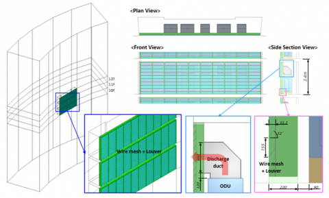
In the current work, the Ansys Fluent 19.2 was utilized to simulate the temperature and velocity distribution of airflow of Samsung brand VRF outdoor units in a practical business office building located in the Empire world project in Erbil City. The (23-floor) Empire business towers comprise four buildings, two of which have already been finished, and the remaining two buildings are under construction. The VRF outdoor units are installed on the balconies and are protected by a louver and wire mesh. Each floor is served by five outdoor units with different capacities. The hot discharge air is exhausted to the environment by the outdoor units’ air direction adjuster, fresh air come into the units through the louver inlet on the front side. Figure 3 presents the layout of the isometric view of the building with different views. The front view describes a wire mesh fence and aluminum louvers that hide the outdoor units. But the side view shows the louvers angle (about 51°) and the openings inlet dimensions for airflow.
Figure 3. Isometric view of a 23-floor office commercial building and the VRF outdoor unit with discharge duct
For such large buildings, the layer-based VRF air conditioning systems are specially designed for zone cooling in summer as the VRF outdoor unit systems are placed separately on every floor and installed on the balconies together. For the current project, each floor consists of five offices with different sizes and cooling load capacities. There are five VRF outdoor units installed on each floor with a capacity of 2*10, 12, 14, 16 hp, except for the first floor, where there are additional indoor units (two units with 14 kW) that serve the reception zone. The outdoor units for the first floor will be 10*2, 12, 2*16 hp. All specification data for the chosen models are available in the product Databook catalog as shown in Table 1 [16].
Table 1. VRF outdoor unit specifications and models
|
Model |
QL (kW) |
CMM |
COP |
QH (kW) |
|
AM100HXVFGH |
28 |
205 |
3.87 |
35.23 |
|
AM120HXVFGH |
33.6 |
255 |
4 |
42 |
|
AM140HXVFGH |
40 |
255 |
3.82 |
48.9 |
|
AM160HXVFGH |
45 |
255 |
3.81 |
56.81 |
The thermal performance of the VRF outdoor units mainly depends on the suction air temperature of condensing units. In terms of that, the efficiency of cooling operations reduces with an increase in coil air temperature. Moreover, due to placing the condensing units on each floor in the same location of balconies, the high temperature of the dissipated heat could result in thermal plume influence. So, the steadily rising heat will consequently increase the temperature of the outdoor air for the top floors` systems, leading to an air short-circuit phenomenon for the outdoor units on those floors. This phenomenon occurs when exhaust air from the outdoor unit is drawn back into the suction vent of the upper units. When the suction temperature reaches the operating limit value (i.e., 54℃ in this issue), a high-pressure cut-off will occur (operation stops).
Figure 4. Effect of condensing air temperature on the cooling capacity and input power
Figure 4 displays the effect of the ambient air temperature on the cooling capacity and power input of the VRF system during the cooling season. As the outdoor temperature increases, there will be a significant drop in capacity, especially when it rises above 35℃ (standard conditions). The heat from the outdoor unit is dissipated into the surrounding environment, which cools it down and condenses the flowing refrigerant from vapor to liquid. The rate of heat and the amount at which it transfers depend upon the temperature variation between the ambient air and the refrigerant. The higher the temperature of the ambient air, the less heat is dissipated to the environment by the outdoor condensing unit, and consequently, the less cooling effect is produced by the evaporators. The average coefficient of performance (COP) will be reduced by 3.25% of its value for each 1℃ increase in the suction temperature as displayed in Figure 5. Since the increase in the suction temperature leads to a drop in the cooling capacity and consumes more power input, consequently the coefficient of performance decreases.
Figure 5. Effect of condensing air temperature on the coefficient of performance
The estimation of the total heat dissipated from the VRF outdoor unit was done by using the performance of refrigerator equations. The purpose of a refrigerator is to keep the refrigerated zone at a low temperature by extracting heat from it. The performance of refrigerators and heat pumps is described in reference to the coefficient of performance (COP), and expressed as [17]:
$\mathrm{COP}=\frac{\text { Desired output }}{\text { Required input }}=\frac{\text { Cooling effect }}{\text { Work input }}=\frac{\mathrm{Q}_{\mathrm{L}}}{\mathrm{W}_{\mathrm{in}}}$ (1)
The work input to the compressor is given by
$\mathrm{W}_{\text {in }}=\frac{\mathrm{Q}_{\mathrm{L}}}{\operatorname{COP}}$ (2)
The total heat dissipated by the condensing units is given by
$\mathrm{Q}_{\mathrm{H}}=\mathrm{Q}_{\mathrm{L}}+\mathrm{W}_{\text {in }}$ (3)
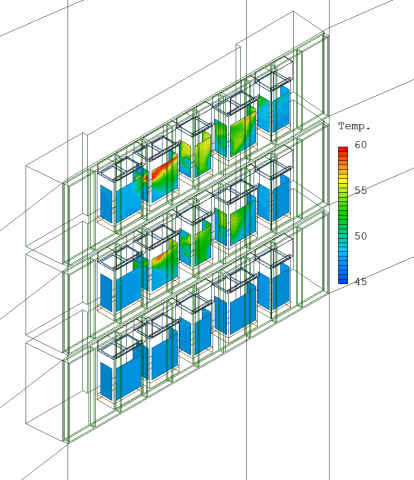
In the current work, the Ansys Fluent 19.2 was utilized to simulate the temperature and airflow distribution in the cooling mode of outdoor units in an office building. The building is designed with 115 outdoor units placed on 23 floors of the building. The geometry was created in a three-dimensional cad drawing. The geometry was later meshed and solved by Ansys fluent in the current and proposed design. The steady-state incompressible Reynolds-averaged Navier–Stokes (RANS) method is applied due to the computational estimate and modeling accuracy. The standard k − epsilon two-equation turbulence model has been utilized for this research. In the current design, the discharge air of the outdoor units is exhausted downward by the inclined louver and then sucked into the upper outdoor units due to the buoyancy effect to increase the suction temperature of the outdoor units. The higher the floor, the higher the suction temperature, as shown in Figure 6 and Figure 7.
Figure 6. Outdoor air temperature distributions on top floors (F10-12) for VRF outdoor units for the current design
Figure 7. Outdoor air temperature distributions on top view for (F11) for VRF outdoor units for current design
In the proposed design, when the front louver of the discharge duct is removed, the discharge air can flow directly into the atmosphere without any resistance, as shown in Figure 8 and Figure 9. Therefore, the short-circuit of the discharge air is reduced and the on-coil air temperature of the condensing units is also lowered.
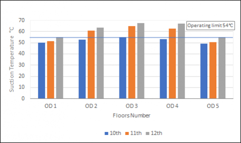
For the current design, even on the 10th floor, the suction temperature of the condensing unit exceeds the operating range, and the suction temperature of all outdoor units on the 12th floor exceeds the operating range. But for the proposed design, even if the outdoor units of three floors operate at the same time, the suction temperature of all outdoor units is lower than the operating range as seen in Figure 10 and Figure 11.
Erbil is an arid province, with hot weather most of the year. Despite an ambient temperature of 48℃ in summer in Erbil, the maximum suction temperature of the condenser unit will reach 67.5℃. Most of the outdoor units exceed the operating limit of 54℃. Moreover, the suction air temperature of the outdoor units located on the right and left sides is lower than the outdoor units located in the center. This is indicated that some hot air is recirculated due to the secure installation space for ventilation in both designs as shown in Figure 12 and Figure 13. The louvers represent not only in their design function as observable barriers but also as an obstacle to airflows.
Figure 8. Outdoor air temperature distributions on top floors (F10-12) for VRF outdoor units for the proposed design
Figure 9. Outdoor air temperature distributions on top view for (F11) for VRF outdoor units for proposed design
Figure 10. Intake air temperature distributions of the VRF air conditioners for current design on top floors (F10-12)
Figure 11. Intake air temperature distributions of the VRF air conditioners for proposed designs on top floors (F10-12)
Figure 12. Comparison of Suction temperature distributions for each outdoor units in current design
Figure 13. Comparison of Suction temperature distributions for each outdoor units in proposed design
A numerical analysis of the performance of VRF air conditioners is carried out for various designs of placing the condensing units on building balconies. Two conditions of design were analyzed: current design and proposed design. The aim of this study is to provide the guidelines for installing condensing units on the building balconies in order to optimize the performance of units and power consumption. The results of the airflow analysis conducted for the outdoor units to be installed at Empire Business Towers in Iraq are as follows:
1. Current design: The discharge air of the outdoor units cannot be exhausted far to the outside by the downward inclined louver, but moves downward and is sucked into the upper outdoor units by the buoyancy effect. Therefore, the suction air temperature of the condensing units rises, and the higher the floor, the higher the suction air temperature of the outdoor units. From the 3rd floor, the on-coil air temperature of entire outdoor units exceeds the operating range.
2. Proposed design: If the front louver of the discharge duct is removed, the discharge air is exhausted farther outward and less is sucked into the upper outdoor units. Because the discharge duct is short and high, the discharge air rises upward, and part of the discharge air is sucked into the upper floor outdoor unit. The higher the floor, the higher the on-coil air temperature of the condensing units. To reduce the short-circuit of the discharge air, either the length of the discharge duct should be increased or the height of the discharge duct should be decreased.
3. The cooling capacity of the condensing unit was decreased by 21% when raising the suction air temperature from the standard condition of 35 to the maximum summer ambient temperature of 48℃ that reaches in Erbil weather, while the input power consumption was increased by approximately 3%.
4. The coefficient of performance was decreased by 25% when raising the condenser suction air temperature from 35 to 48℃. Therefore, it is very important to select the VRF outdoor unit for Erbil City as 48℃ in all projects to overcome these losses and reductions in performance.
It is recommended to place the outdoor units in open spaces with sufficient ventilation to avoid high suction condenser temperatures that have significant detrimental effects on the working of the systems` efficiencies and energy consumption in practical operation. The results of the CFD simulation could be used to come up with design ideas that will keep performance and predict possible failures without having to reinstall or make countermeasures.
Future research can be suggested to implement more parameters like wind speed, humidity, louver opening and angles, and building characteristics to investigate the thermal plume effect. Also, a field test is essential to compare and validate the CFD simulation results.
The author of this study would like to acknowledge the staff of the Mechanical and Mechatronic Engineering department/Salahaddin University-Erbil for their generous assistance and support.
|
AC |
Air conditioer |
|
COP |
Coefficeint of performance |
|
CFD |
Computational fluid dynamics |
|
CMM |
Air flow rate m3. min-1 |
|
DC |
Direct current |
|
HP |
Heat pump |
|
HR |
Heat Recovery |
|
K |
Turbulence kinetic energy |
|
QL |
Evaporator heat absorption kJ/s-1 |
|
GH |
Condenser heat dissipation kJ/s-1 |
|
Win |
Compressor power input kJ/s-1 |
|
T |
Temperature °C |
|
V |
Velocity m. s-1. |
|
Greek symbols |
|
|
ε |
Dissipation rate |
|
Subscripts |
|
|
L |
Heat absorption |
|
H |
Heat dissipation |
|
in |
Input power |
[1] Yau, Y.H., Amir, M. (2020). Energy use analysis of the variable refrigerant flow (VRF) system versus the multi-split unit using TRNSYS. Heat and Mass Transfer, 56: 671-690. https://doi.org/10.1007/s00231-019-02726-7
[2] Zhang, Y., Wei, Z.Y., Long, E.S., Zhang, X., Guo, S.R. (2017). Outdoor air thermal plume simulation of layer-based VRF air conditioners in high-rise buildings. Energy Procedia, 142: 3787-3792. https://doi.org/10.1016/j.egypro.2017.12.277
[3] Handbook, A.J.A.S.O.H., Refrigerating and A.-C.E. Inc, HVAC Systems and Equipment, Room air distribution equipment. 2016: p. 20.1-20.15. t, Room air distribution equipment. 2016: p. 20.1-20.15. https://www.ashrae.org/, accessed on Jun. 10, 2022.
[4] Thornton, B. and A.J.P.N.N.L.R. Wagner, WA, USA, Variable refrigerant flow systems. 2012. https://www.15000inc.com/wp/wp-content/uploads/VRF-Report-by-GSA.pdf, accessed on Jun. 11, 2022.
[5] Systems, A.J.U.L., ASHRAE handbook: HVAC systems and equipment. 2016: pp. 17.1-17.10. https://www.ashrae.org/, accessed on Jun. 18, 2022.
[6] Chow, T., Lin, Z., Wang, Q.W. (2000). Effect of building re-entrant shape on performance of air-cooled condensing units. Energy and Buildings, 32(2): 143-152. https://doi.org/10.1016/S0378-7788(99)00048-1
[7] Chien, N.B., Dung, N.V., Dung, T.Q., Cuong, N.T., Le, K.H. (2020). CFD simulation of multi-outdoor unit configuration design for a building. IOP Conference Series: Earth and Environmental Science, 505(1): 012007. https://doi.org/10.1088/1755-1315/505/1/012007
[8] Chow, T., Lin, Z., Wang, Q.W. (2001). Flow analysis of condenser cooling air delivery via building light well. Applied Thermal Engineering, 21(8): 831-843. https://doi.org/10.1016/S1359-4311(00)00084-3
[9] Chow, T.T., Lin, Z. (1999). Prediction of on-coil temperature of condensers installed at tall building re-entrant. Applied Thermal Engineering, 19(2): 117-132. https://doi.org/10.1016/S1359-4311(98)00042-8
[10] Bojic, M., Lee, M., Yik, F. (2002). Influence of a depth of a recessed space to flow due to air-conditioner heat rejection. Energy and Buildings, 34(1): 33-43. https://doi.org/10.1016/S0378-7788(01)00078-0
[11] Xue, H., Xu, B., Wu, J., Wei, Y. (2007). Prediction of temperature rise near condensing units in the confined space of a high-rise building. Building and Environment, 42(7): 2480-2487. https://doi.org/10.1016/j.buildenv.2006.06.011
[12] Yau, Y., Pean, H.L. (2014). The performance study of a split type air conditioning system in the tropics, as affected by weather. Energy and Buildings, 72: 1-7. https://doi.org/10.1016/j.enbuild.2013.12.010
[13] Choi, S.H., Lee, K.S., Kim, B.S. (2005). Effects of stacked condensers in a high-rise apartment building. Energy, 30(7): 968-981. https://doi.org/10.1016/j.energy.2004.08.004
[14] Avara, A., Daneshgar, E. (2008). Optimum placement of condensing units of split-type air-conditioners by numerical simulation. Energy and Buildings, 40(7): 1268-1272. https://doi.org/10.1016/j.enbuild.2007.11.011
[15] Bruelisauer, M., Meggers, F., Saber, E., Li, C., Leibundgut, H. (2014). Stuck in a stack—temperature measurements of the microclimate around split type condensing units in a high rise building in Singapore. Energy and Buildings, 71: 28-37. https://doi.org/10.1016/j.enbuild.2013.11.056
[16] Samsung DVM Desert, Technical Data Book 2013. https://www.samsunghvac.com/commercial/dvm-s, accessed on Jun. 20, 2022.
[17] Cengel, Y.A., Boles, M.A., Kanoglu, M. (2011). Thermodynamics: An Engineering Approach. McGraw-Hill New York.