Zhe Li | Xiaoqiang Ren* | Hongming He
© 2022 IIETA. This article is published by IIETA and is licensed under the CC BY 4.0 license (http://creativecommons.org/licenses/by/4.0/).
OPEN ACCESS
The effect of thermo-mechanical coupling is a key factor that needs to be fully considered during the construction, operation, and maintenance of tunnels in high ground temperature areas so that measures could be taken to reduce the frequency of damages and accidents. However, research methods and theoretical results for tunnel support structures under high temperature conditions and layered soft rock environment are insufficient, therefore, to fill in this research blank, this paper aims to study the damage deterioration mechanism of tunnel structure under thermo-mechanical coupling effect and its maintenance. In the second chapter, this paper gave a diagram showing the coupling mechanism of several physical fields, including the stress field, the seepage field, and the temperature field, and proposed control equations for the coupling of these fields during the damage deterioration process of the tunnel structure. In the third chapter, this paper applied two yield failure criterions, namely the Mohr-Coulomb criterion and the maximum tensile stress strength criterion to the analysis of the evolution of compression shear failure and tensile failure, and built scientific evolution equations for the permeability coefficient and the thermal conductivity coefficient. At last, experimental results verified the effectiveness of the constructed model and the analysis method.
thermo-mechanical coupling, tunnel structure, surrounding rock, damage deterioration, maintenance
Tunnel projects are facing more engineering challenges as the tunnels are becoming longer, bigger, deeper, and clustered these days [1-9]. Under the condition of high ground temperature, the stress on tunnel support structure and surrounding rock is even more complex under the multiple and simultaneous actions of temperature, stress, internal water pressure, and ground stress, etc. [10-15]. The actions of multiple stresses on the tunnel support structure are interrelated and mutually affected, not just simply superimposed. During the construction and operation of the deep-buried long big tunnels, the thermal and mechanical physical fields are combined significantly [16-22]. Under the impact of large temperature difference of “hot inside and cold outside”, high-gradient temperature field would appear in the tunnel, which can cause serious deformation to lining concrete of the tunnel support structure, and it might damage the tunnel structure in severer cases [23-26]. At the same time, the surrounding rock of the tunnel support structure is subjected to high stress, which can lead to phenomena as such as cracking, hydraulic cracking, and instability, bringing threats to the safe operation of the tunnel. Therefore, the effect of thermo-mechanical coupling needs to be fully considered during the construction, operation, and maintenance of tunnels in high ground temperature areas so that measures could be taken to reduce the frequency of damages and accidents.
Scholars Zhang et al. [27] took the operating heat-supply tunnels in Beijing as the subject to study the durability of its lining structure under the action of large thrust and thermal effect. Their work was done from two aspects: using ESEM-EDS to analyze the disease composition of the lining structure, and the indoor durability experiment. The ESEM-EDS results suggested high carbon content in the field specimens, and carbonization was the main durability problem of the concrete lining structure of the heat-supply tunnel. Wu et al. [28] proposed that subway tunnels and their surrounding geotechnical media could be regarded as an entirety, and the tunnel geo-material system (TGS), and the stability and durability of the subway tunnels are subjected to the responses of the TGS to the thermal, hydraulic and mechanical loadings and their coupled effects. Combining equilibrium, motion, constitutive and compatibility equations, they developed a numerical model for coupling the THM processes in the TGS, which considered the full coupling between the thermal (temperature variation), hydraulic (water seepage), mechanical (subsidence) processes and changes in the material properties, such as stress-strain relation, viscosity, thermal conductivity, and hydraulic conductivity. By comparing results of field tests, laboratory experiments and numerical simulations, they verified the developed model, and the good agreement between the modeling results and the comparison data proved that the developed model can well describe the THM behavior of subway tunnels in TGS and its evolution.
Currently, there’re quite a few studies on the damage deterioration mechanism of tunnel support structures, the physical models, and the monitoring, and they have attained many research results, however, the existing studies are mostly limited to normal temperature status, the research objects are generally tunnel support structures made of homogeneous materials, and the research methods and theoretical results for tunnel support structures under high temperature conditions and layered soft rock environment are insufficient, therefore, to fill in this research blank, this paper studied the damage deterioration mechanism of tunnel structure under thermo-mechanical coupling effect and its maintenance. In the second chapter, this paper gave a diagram showing the coupling mechanism of several physical fields, including the stress field, the seepage field, and the temperature field, and proposed control equations for the coupling of physical fields during the damage deterioration process of the tunnel structure. In the third chapter, this paper applied two yield failure criterions, namely the Mohr-Coulomb criterion and the maximum tensile stress strength criterion to the analysis of the evolution of compression shear failure and tensile failure, and built scientific evolution equations for the permeability coefficient and the thermal conductivity coefficient. At last, experimental results verified the effectiveness of the constructed model and the analysis method.
Figure 1. Longitudinal section of the tunnel
Figure 2. The coupling mechanism of physical fields
Figure 1 gives a diagram of the longitudinal section of the tunnel. In the figure, the strength and deformation of tunnel support structure and surrounding natural rock mass have certain random features, and such randomness is a main driving factor for the micro cracks in the tunnel support structure and surrounding rock after subjected to the action of high stress. In order to describe the effect of such randomness on the mechanical behavior of the tunnel support structure and surrounding rock, in this paper, assuming: MO represents the elastic modulus of the tunnel support structure and surrounding rock; z represents the cohesion force; ψ represents the internal friction angle; φp represents the tensile strength; a represents (MO, z, ψ, φp); n represents the shape parameter of the distribution function describing the uniformity of the parameters; δ represents the position parameter of the distribution function describing the mean values of the parameters, then the four physical and mechanical parameters meet the following formula:
$g(a)=\left\{\begin{array}{l}0, a<0 \\ \frac{n}{\delta}\left(\frac{a}{\delta}\right)^{n-1} e^{-\left(\frac{a}{\delta}\right)^n}, a \geq 0\end{array}\right.$ (1)
Figure 2 gives a diagram showing the coupling mechanism of physical fields. The paragraph below constructed control equations for the coupling of physical fields during the damage deterioration process of the tunnel structure, including the stress field, the seepage field, and the temperature field.
In terms of the stress field, assuming: H represents the shear modulus; C represents the damage variable function of shear modulus; ρij represents the total strain; ρpll represents the elastic strain; ρell represents the plastic strain; φij represents the total stress; e represents the pore water pressure; ξij represents the Kronecker coefficient; ρOll represents the temperature strain; α represents the thermal expansion coefficient; O represents the current temperature; O0 represents the initial temperature; μ represents the Lamé coefficient; C represents the damage variable function; ρll represents the total volume strain; ρell represents the plastic volume strain; ρOll represents the volume strain caused by temperature; μr represents the plastic multiplier; g represents the plastic potential function; this paper introduced the effect of damage deterioration based on pore water pressure and temperature stress and constructed the constitutive equation below:
$\phi_{i j}+e \xi_{i j}=2 H(C)\left(\rho_{i j}-\rho_{i j}^\lambda-\rho_{i j}^s\right)+\mu(C)\left(\rho_{i j}-\rho_{i j}^E-\rho_{i j}^O\right) \xi_{i j}$ (2)
where,
$\rho_{i j}=\rho_{i j}^p+\rho_{i j}^e+\rho_{i j}^O$ (3)
$\rho_{i j}^e=\mu_r \frac{\partial g}{\partial \phi_{i j}}$ (4)
$\rho_{i j}^T=\alpha\left(O-O_0\right) \xi_{i j}$ (5)
As can be known from above formulas, ρpll, ρell, and ρOll constitute the total strain φij, that is, the constitutive equation takes into account the coupling between seepage, temperature, damage, and stress. Assuming: σ represents the density of surrounding rock; gi represents volume force component of the rock mass medium, then the following formula gives the equilibrium equation of elasticity:
$\phi_{i j, j}+\sigma g_i=0$ (6)
By combining the constitutive equation with the equilibrium equation, an equilibrium equation considering the seepage, temperature, and elasticity could be constructed:
$\left\{2 H(C)\left(\rho_{i j}-\rho_{i j}^e-\rho_{i j}^O\right)+\mu(C)\left(\rho_{l l}-\rho_{l l}^e-\rho_{l l}^O\right) \xi_{i j}-e \xi_{i j}\right\}_j+\sigma g_i=0$ (7)
In terms of the seepage field, a seepage control equation considering the coupling seepage, temperature, damage and stress could be constructed as follows:
$\frac{1}{N} \frac{\partial e}{\partial o}+\frac{m}{r} \frac{\partial r}{\partial o}=\frac{1}{r}\left(-w(C)_{i, i}+w_u\right)-\beta \frac{\partial \rho_{l l}}{\partial o}+\alpha \frac{\partial O}{\partial o}$ (8)
Assuming: l represents the permeability coefficient of rock mass; wu represents the fluid source term; α represents the undrained coefficient of thermal expansion; N represents the Biot modulus; o represents the time; m represents the porosity of rock mass; r represents the saturation of rock mass; w(C)i represents the seepage flow, and it satisfies w(C)i=l(C)(e-ε0ha)i.
Figure 3. Heat transfer process in the tunnel
Heat convection and heat transfer would occur during the construction, operation and maintenance of tunnels in high ground temperature areas. Figure 3 shows the heat transfer process in the tunnel. In terms of the temperature field, the following formula gives a temperature control equation considering the effects of the damage deterioration of the tunnel support structure and the heat transfer of the surrounding rock mass:
$S H^T \frac{\partial O}{\partial o}+\nabla \bullet w(C)^T+\sigma_0 S H_q L T_q \bullet \nabla O-L T_u^T=0$ (9)
Assuming: O represents the temperature; σ0 represents the fluid density; SHq represents the specific heat capacity of the fluid; LTq represents the specific flow rate of the fluid; LTuT represents the volume heat source strength; SHT represents the equivalent specific heat capacity, and it satisfies SHT=σSHu+mrσ0SHq; σ represents the density of the rock mass; SHu represents the specific heat capacity of the rock mass; w(C)T represents the heat flux; C represents the damage variable function, and it satisfies w(C)T =μ(C)Oμ; μ represents the thermal conductivity of the rock mass.
When a tunnel is constructed, the stress field of the tunnel support structure and the surrounding natural rock mass will be re-adjusted, and the superposition of temperature tensile stress, internal water pressure, and seepage pressure will act on the surrounding rock; under high stress, the surrounding rock will yield and produce damage deterioration. When judging whether the tunnel support structure and surrounding rock yield or not, two yield failure criterions, the Mohr-Coulomb criterion and the maximum tensile stress strength criterion, were adopted to analyze the evolution of compression shear failure and tensile failure. Assuming: φ1 represents the first principal stress; φ3 represents the third principal stress; D represents the cohesion force of the rock mass; ψ represents the friction angle of the rock mass; φo represents the tensile strength of the rock mass, then there are:
$\left\{\begin{array}{l}g^r=\phi_1-\phi_3 M_\psi+2 D \sqrt{M_\psi} \\ M_\psi=\frac{1+\sin \psi}{1-\sin \psi}\end{array}\right.$ (10)
$g^o=\phi_o-\phi_3$ (11)
Since the tunnel support structure and surrounding rock subjected to high stress will yield and produce damage deterioration, its overall performance will decline greatly, and its four physical and mechanical parameters MO, z, ψ, φo will decrease accordingly. In order to construct a coupling model that can fully consider the effect of damage deterioration of the surrounding rock, this paper introduced the equivalent plastic strain ρe and take the deterioration of parameters z, ψ, and φo into account. Assuming: MO0, z0, ψ0, and φo0 respectively represent the initial values of the four parameters; MOc, zc, ψc, and φoc respectively represent the corresponding residual values; ρ^eMO, ρ^ez, ρ^eψ, and ρ^eφo respectively represent the equivalent plastic strain when the four parameters reach the residual values, then the following formulas give the deterioration equations of the strength parameters of the surrounding rock mass of the tunnel support structure:
$\rho^e=\sqrt{\frac{2}{3}\left(\rho_1^e \rho_1^e+\rho_2^e \rho_2^e+\rho_3^e \rho_3^e\right)}$ (12)
$M O=\left\{\begin{array}{l}M O_0-\frac{\hat{\rho}^e}{\hat{\rho}_{M O}^e}\left(M O_0-M O_d\right), 0 \leq \hat{\rho}^e \leq \hat{\rho}_{M O}^e \\ M O_c, \hat{\rho}^e \geq \hat{\rho}_{M O}^e\end{array}\right.$ (13)
$z=\left\{\begin{array}{l}z_0-\frac{\hat{\rho}^e}{\hat{\rho}_d^e}\left(z_0-z_c\right), 0 \leq \hat{\rho}^e \leq \hat{\rho}_d^e \\ z_c, \hat{\rho}^e \geq \hat{\rho}_d^e\end{array}\right.$ (14)
$\psi=\left\{\begin{array}{l}\psi_0-\frac{\hat{\rho}^e}{\hat{\rho}_\psi^e}\left(\psi_0-\psi_c\right), 0 \leq \hat{\rho}^e \leq \hat{\rho}_\psi^e \\ \psi_c, \hat{\rho}^e \geq \hat{\rho}_\psi^e\end{array}\right.$ (15)
$\phi_o=\left\{\begin{array}{l}\phi_{o 0}-\frac{\hat{\rho}^e}{\hat{\rho}_{\varepsilon_o}^e}\left(\phi_{o 0}-\phi_{o c}\right), 0 \leq \hat{\rho}^e \leq \hat{\rho}_{\varepsilon_o}^e \\ \varepsilon_{o c}, \hat{\rho}^e \geq \hat{\rho}_{\varepsilon_o}^e\end{array}\right.$ (16)
For tunnel support structure and surrounding rock after subjected to high stress, micro cracks would appear, and the permeability coefficient and thermal conductivity would change accordingly. In order to quantitatively describe the damage evolution process of each physical and mechanical parameter, this paper used the damage variable C to define the damage deterioration of the tunnel support structure and surrounding rock, and Formula 17 gives its damage evolution equation:
$C=\left\{\begin{array}{l}\frac{M O_0-M O}{M O_0-M O_d}, 0 \leq \hat{\rho}^e \leq \hat{\rho}_{M O}^e \\ 1, \hat{\rho}^e \geq \hat{\rho}_{M O}^e\end{array}\right.$ (17)
According to above formula, the tunnel support structure and its surrounding rock in the plastic state will begin to show damage deterioration. When ρe is less than ρ^eMO, the damage of tunnel support structure and surrounding rock increases linearly; when it is greater than ρ-EP, the damage values of the tunnel support structure and its surrounding rock are both 1, that is, the damage deterioration trend slows down.
After subjected to high stress, micro cracks would appear on the tunnel support structure and its surrounding rock, since the damaged positions might develop continuously and turn into macro cracks, this will greatly affect its seepage field and temperature field. In order to construct a scientific evolution equation for permeability coefficient, this paper integrated the porosity, stress state, and crack opening degree of the tunnel support structure and surrounding rock into a damage influence factor and defined a corresponding influence coefficient. Assuming: l0 represents the initial permeability coefficient of surrounding rock; βl represents the influence coefficient of damage deterioration on l; C represents the damage variable, then there is:
$l=l_0 e^{\beta_l C}$ (18)
In order to construct a scientific evolution equation for thermal conductivity, similar to the evolution equation of permeability coefficient, this paper integrated the various factors of the thermal conductivity of surrounding rock and also defined a corresponding influence coefficient. Assuming: μ represents the thermal conductivity of the damaged tunnel support structure; μ0 represents the initial thermal conductivity; βμ represents the influence coefficient of the damage on thermal conductivity; C represents the damage variable, then there is:
$\mu=\mu_0 e^{\beta_\mu C}$ (19)
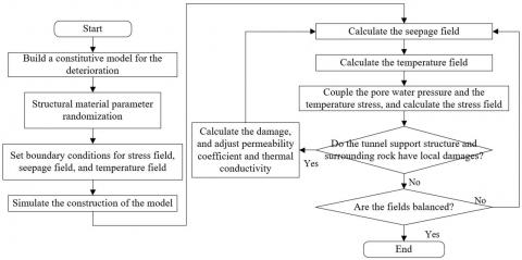
To investigate the damage deterioration mechanism of the tunnel structure, this paper employed the sequential coupling strategy to integrate the calculation modes of the three fields, finally, the constructed thermo-mechanical coupling model control equations were numerically solved, and the calculation steps are shown in Figure 4.
Figure 4. Calculation steps
Table 1. Parameters of the thermo-mechanical coupling analysis model of the tunnel
|
Name |
Material |
Elastic modulus |
Poisson's ratio |
Density specific heat capacity |
Thermal conductivity |
Thickness |
Cohesion force |
Internal friction angle |
|
Soil layer A |
Miscellaneous soil |
1.57 |
0.0369 |
1857 |
1248 |
3 |
7 |
29 |
|
Soil layer B |
Sandy soil |
1.69 |
0.05 |
1629 |
926 |
6 |
1 |
32 |
|
Soil layer C |
Pebble gravel |
1.24 |
0.01 |
2514 |
942 |
25 |
8 |
36 |
|
Surrounding rock |
Granite |
2.9×10¹⁰ |
17 |
2869 |
257 |
- |
- |
- |
|
Lining |
Concrete |
2.0×10¹⁰ |
15 |
2741 |
223 |
- |
- |
- |
|
Support structure |
Q235 steel |
13.9 |
214 |
7485 |
475 |
- |
- |
- |
Ignoring the distribution difference of temperature in the longitudinal direction of the tunnel structure and combining with the high ground temperature conditions of the tunnel construction site and the geological survey report, this paper set the parameters of the thermo-mechanical coupling analysis model as shown in Table 1.
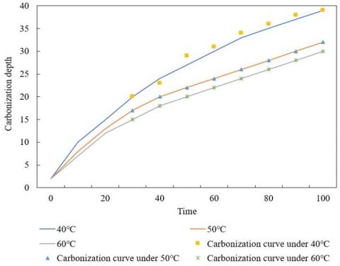
In order to determine the influence coefficient of the environmental temperature of tunnel support structure and surrounding natural rock mass, the change trend of carbonization depth under different stress conditions was investigated. Figure 5 shows the fitting curves of the carbonization depth under different temperatures. According to the figure, the fitting error between the carbonization depth collection points and the fitting curves was relatively small, indicating that selected fitting coefficient was scientific.
Charts a and b in Figure 6 respectively give the longitudinal strain and the hoop strain at each monitoring point on the lining concrete of the target tunnel, showing the actually measured conditions of the influence of thermo-mechanical coupling effect on the lining concrete of the tunnel. As can be seen from Figure 6, both the longitudinal strain and the hoop strain decreased with the increase of the distance from the center of the support structure. Within the range of 5-6 meters, the longitudinal strain and the hoop strain of the lining bottom plate of the tunnel decreased by 50%-60%, therefore, for the target tunnel, during the operation period, attention needs to be paid to the tunnel lining within 6 meters of the fixed brackets of the tunnel support structure. In the figure, the boxes show the bottom plate strain of different sections, and it can be found that the actually measured results were basically consistent with the numerical simulation results, which had further verified that the proposed thermo-mechanical coupling model control equations were scientific and effective.
Figure 7 shows the changes of the volume loss of tunnel support structure and surrounding rock caused by damage. According to the trend of the curve, we can see that the three physical fields of stress field, seepage field, and temperature field exhibited radial distribution, which was consistent with the distribution of the positions of damage deterioration. Compared with other intact positions with the same radius, the seepage pressure at the positions of damage deterioration was higher and the temperature was lower. The damage degree of the damage deterioration position and high seepage pressure would develop deeper into the surrounding rock with the passage of the operation time.
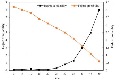
Then, the damage variable function of tunnel support structure and surrounding rock was used to calculate the reliability degree and failure probability of tunnel damage deterioration, and Figure 8 gives the changes of these two indexes. As can be seen from the figure, after operating for 50 years, under the constraint of an allowable deformation of 10 mm, the reliability degree of damage deterioration of the target tunnel is 8.014, and the failure probability is 0.524. According to the specifications and engineering experience in high ground temperature areas, we can know that the reliability of the target tunnel is ideal.
Figure 5. Fitting curves of carbonization depth under different temperatures
Figure 6. Strain change of lining concrete
Figure 7. Changes of the volume loss of tunnel support structure and surrounding rock
Figure 8. Changes of reliability degree and failure probability of tunnel damage deterioration
This paper studied the damage deterioration mechanism of tunnel structure under the effect of thermal coupling and its maintenance. At first, this paper gave a diagram showing the coupling effect of physical fields including the stress field, seepage field and temperature field, and constructed control equations for the coupling of these fields during the damage deterioration of the tunnel structure. Then, this paper applied two yield failure criterions, the Mohr-Coulomb criterion and the maximum tensile stress strength criterion to the analysis of the evolution of compression shear failure and tensile failure, and built scientific evolution equations for the permeability coefficient and the thermal conductivity. After that, combining with experiment, this paper plotted fitting curves of carbonization depth under different temperatures, gave the changes of the longitudinal strain and hoop strain at each monitoring point on the lining concrete of the target tunnel, measured the actual conditions of the effect of the thermo-mechanical coupling on the lining concrete of the tunnel, and the verified that the proposed thermo-mechanical coupling model control equations were scientific and effective. At last, this paper gave the changes of the volume loss of the tunnel support structure and surrounding rock caused by damage and the reliability degree of tunnel damage deterioration. Based on the specifications and engineering experience in high ground temperature areas, it’s judged that the reliability of the target tunnel is relatively ideal.
[1] Cheng, R., Wang, H., Dimitriou, D., Jiang, Z., Cheng, C.K., Tsai, T.Y. (2022). Central femoral tunnel placement can reduce stress and strain around bone tunnels and graft more than anteromedial femoral tunnel in anterior cruciate ligament reconstruction. International Journal for Numerical Methods in Biomedical Engineering, 38(5): e3590. https://doi.org/10.1002/cnm.3590
[2] Liu, Y., Zhang, Q., Liu, R., et al. (2022). Compressive stress-hydrothermal aging behavior and constitutive model of shield tunnel EPDM rubber material. Construction and Building Materials, 320: 126298. https://doi.org/10.1016/j.conbuildmat.2021.126298
[3] Choi, C., Sukegawa, H., Mitani, S., Song, Y. (2017). Investigation of ramped voltage stress to screen defective magnetic tunnel junctions. Semiconductor Science and Technology, 33(1): 015006. https://doi.org/10.1088/1361-6641/aa99bb
[4] Castro, S.O., Soler, J.P., Andrade, C.F., Delucchi, H.A. (2000). Rock mass stress release in the alfalfal main water tunnel: Evidence and remedial actions. In ISRM International Symposium, Melbourne, Australia.
[5] Sun, H.S., Wang, L.W., Chen, Y.D., Dong, Y., Zhang, J.H., Sun, W.B. (2018). Nonlinear analysis of tunnel deformation and mechanisms of stress transfer caused by basement excavation. Soil Mechanics and Foundation Engineering, 55(5): 298-304. https://doi.org/10.1007/s11204-018-9540-2
[6] Wang, S., Li, D., Li, C., Zhang, C., Zhang, Y. (2018). Thermal radiation characteristics of stress evolution of a circular tunnel excavation under different confining pressures. Tunnelling and Underground Space Technology, 78: 76-83. https://doi.org/10.1016/j.tust.2018.04.021
[7] Yang, J.H., Jiang, Q.H., Zhang, Q.B., Zhao, J. (2018). Dynamic stress adjustment and rock damage during blasting excavation in a deep-buried circular tunnel. Tunnelling and Underground Space Technology, 71: 591-604. https://doi.org/10.1016/j.tust.2017.10.010
[8] Zhu, B., Fan, J., Shi, X., Liu, P., Guo, J. (2022). Study on rockburst proneness of deep tunnel under different geo-stress conditions based on DEM. Geotechnical and Geological Engineering, 40(3): 1373-1386. https://doi.org/10.1007/s10706-021-01969-8
[9] Shrestha, P., Hill, J., Simmons, D., Meritt, R.J. (2022). Comparison between Computational and Experimental Wall-Shear Stress and Pressure Measurements in a Supersonic Wind Tunnel. In AIAA AVIATION 2022 Forum. https://doi.org/10.2514/6.2022-3677
[10] Xu, T., Yu, L., Cai, M. (2018). Construction simulation and stress characteristics of large span tunnel crossing fault fracture zone. IOP Conference Series: Earth and Environmental Science, 189(2): 022004. https://doi.org/10.1088/1755-1315/189/2/022004
[11] Qiu, J., Shen, Y., Zhang, X., Zhang, Y., Gan, Y., Zhou, X. (2022). Simplified method for predicting time-dependent behavior of deep-buried tunnel considering tunnel excavation rate and stress release effects. International Journal of Applied Mechanics, 14(5): 2250043. https://doi.org/10.1142/S1758825122500430
[12] Jegadeesh Kumar, T., Muttharam, M. (2022). Numerical Study on the Influence of In-Situ Stress Ratio on Stress and Deformation Characteristics of Rock Tunnel. In Stability of Slopes and Underground Excavations, pp. 247-258. https://doi.org/10.1007/978-981-16-5601-9_21
[13] Yang, Y., Zhang, D., Li, S., Yang, L., Jin, L. (2022). In-situ stress test and rockburst analysis in Micang Mountain tunnel. Energy Sources, Part A: Recovery, Utilization, and Environmental Effects, 44(1): 2321-2330. https://doi.org/10.1080/15567036.2019.1649748
[14] Chen, Z., Wang, Z., Su, G., Gao, S., Hu, X. (2022). Construction technology of micro bench cut method for weak rock tunnel with high in-situ stress. Geotechnical and Geological Engineering, 40(3): 1407-1415. https://doi.org/10.1007/s10706-021-01971-0
[15] Savino, P., Tondolo, F. (2021). A new approach for displacement and stress monitoring of tunnel based on iFEM methodology. Smart Materials and Structures, 31(1): 015013. https://doi.org/10.1088/1361-665X/ac3901
[16] Nishimura, T., Fumimura, K., Watariue, M., Kawabata, S., Kohno, M. (2018). Numerical simulation of stress and deformation around tunnel portal. In ISRM International Symposium-10th Asian Rock Mechanics Symposium, Singapore.
[17] Lin, L., Lu, Y., Chen, F. (2018). An analytical solution for stress and displacement field for arbitrarily positioned twin-tunnel excavation at great depth. Mathematical Problems in Engineering, 2018: 2947970. https://doi.org/10.1155/2018/2947970
[18] Shan, Y., Zhou, S., Shu, Y. (2018). Differential settlement and soil dynamic stress of a culvert-embankment transition zone due to an adjacent shield tunnel construction. KSCE Journal of Civil Engineering, 22(7): 2325-2333. https://doi.org/10.1007/s12205-017-1592-8
[19] Lavrikov, S.V., Mikenina, O.A., Revuzhenko, A.F. (2018). Influence of structural parameter included in nonlocal rock mass model on stress concentration around circular tunnel. In IOP Conference Series: Earth and Environmental Science, 134(1): 012037. https://doi.org/10.1088/1755-1315/134/1/012037
[20] Dohmeier, N., Tavassolizadeh, A., Rott, K., Quandt, E., Meyners, D., Reiss, G. (2018). Inverse magnetostrictive stress sensors based on crossed pinned CoFeB/MgO/CoFeB tunnel junctions. Journal of Applied Physics, 124(6): 064501. https://doi.org/10.1063/1.5040040
[21] Kang, L., Zhang, J., Yang, Z., Zou, X., Cheng, H., Zhang, C. (2018). Experimental investigation on shear-stress partitioning for flexible plants with approximately zero basal-to-frontal area ratio in a wind tunnel. Boundary-Layer Meteorology, 169(2): 251-273. https://doi.org/10.1007/s10546-018-0373-3
[22] Xu, C., Liang, L., Chen, Q. (2018). Explicit analytical solutions for surrounding rock stress of a shallow buried tunnel considering seepage effect. European Journal of Environmental and Civil Engineering, 22(s): s149-s163. https://doi.org/10.1080/19648189.2017.1388849
[23] Dai, C., He, C., Xia, W.Y., Li, S.Q. (2018). Test on the stability of soft rock tunnel with high ground stress field influenced by direction of maximum horizontal principle stress. Journal of Southwest Jiaotong University, 53(2): 303-311. http://dx.chinadoi.cn/10.3969/j.issn.0258-2724.2018.02.012
[24] Perminov, N., Perminov, A. (2018). Simulation of strain-stress behavior of a tunnel collector in the combined anthropogenic effects conditions. In IOP Conference Series: Materials Science and Engineering, 456(1): 012083. https://doi.org/10.1088/1757-899X/456/1/012083
[25] Pleshko, M., Revyakin, A., Malishevskaya, N. (2018). Investigation of the influence of the railroad track on the stress state of the tunnel lining. MATEC Web of Conferences, 239: 01020. https://doi.org/10.1051/matecconf/201823901020
[26] Zhou, S., Di, H., Luo, Z., He, C., Zhang, X. (2018). Dynamic stress response of saturated soil subjected to vertical and horizontal moving loads inside a circular tunnel. Proceedings of the Institution of Mechanical Engineers, Part F: Journal of Rail and Rapid Transit, 232(6): 1758-1773. https://doi.org/10.1177/0954409717748788
[27] Zhang, J., He, S., Xie, N., Chen, X., Guo, Y. (2018). Durability experimental study on the heat-supplying tunnel lining structure under thermal-mechanical coupling. IOP Conference Series: Materials Science and Engineering, 452(2): 022104. https://doi.org/10.1088/1757-899X/452/2/022104
[28] Wu, D., Zhang, Y., Zhao, R., Deng, T., Zheng, Z. (2017). A coupled thermal-hydraulic-mechanical application for subway tunnel. Computers and Geotechnics, 84: 174-182. https://doi.org/10.1016/j.compgeo.2016.12.006