Bernardo Buonomo | Oronzio Manca* | Sergio Nardini | Renato Elpidio Plomitallo
(This article is part of the Special Issue 7th int. Conf. AIGE-IIETA and 16th Conf. AIGE)
© 2022 IIETA. This article is published by IIETA and is licensed under the CC BY 4.0 license (http://creativecommons.org/licenses/by/4.0/).
OPEN ACCESS
An investigation on a Latent Heat Thermal Energy Storage System (LHTESS) based on a phase change material (PCM) partially filled with metal foam is accomplished. The geometry of the system under investigation is a vertical shell and tube LHTES made with two concentric aluminum tubes with an internal circular tube. The internal surface of the hollow cylinder is assumed at a constant temperature above the melting temperature of the PCM. The external upper and lower surfaces are assumed adiabatic whereas heat losses toward the ambient on the lateral surface of the external cylinder are considered. A numerical model is employed to simulate the behavior of the PCM embedded with the metal foam. The phase change of the PCM is modeled with the enthalpy porosity theory while the metal foam is considered as porous media using the Darcy-Forchheimer law. The results are given in terms of average liquid fraction, average temperature, enthalpy and heat loss. It is shown that the metal foam filling ratio increase determines a decrease of melting time whereas the increase of external heat transfer causes a decrease of the stored energy and an increase of melting time.
latent heat thermal energy storage, phase change material, metal foam, partially filled system, heat losses
One of the most common approaches to reducing carbon emissions and meeting our society's energy demands is to employ renewable energy. The fundamental disadvantage of many renewables is their intrinsic intermittency, which results in a mismatch between energy availability and consumer demand.
Thermal energy storage (TES) technology is one approach, which primarily uses sensible heat (180 MJ/m3), latent heat (360 MJ/m3), or thermochemical energy (1800 MJ/m3) with various energy density ranges [1]. Solid-liquid phase change materials are commonly used in latent heat thermal energy storage (LHTES). The energy density of latent heat storage utilizing PCMs is substantially higher than that of sensible heat storage, resulting in less material mass and/or lower tank volumes [2].
Sensible, Latent, and Chemical Thermal Energy Storage (TES) are the three forms of TES. Due to their large TES capacities per unit mass and capacity to work with a short temperature range, latent TES systems have been the most developed in recent years [3], as the heat interaction occurs at quasi-constant temperature [4]. One of the most promising of these systems is based on PCMs. Due to the high conductivity of metal foam, the combination of PCMs and metal foam in LHTESS is able to overcome the weakness of thermal conductivities and poor heat transfer capabilities of PCMs. Organic, inorganic, and eutectic PCMs are the three types of PCMs, each with a different range of phase transition temperatures. PCMs have a high thermal storage capacity, but their thermal conductivity is modest; as a result, they are frequently increased using various ways [5-8].
One of these techniques is to employ metal foams, which are extensively used because metal foam enhances the heat transfer in the LHTESS due to lower thermal resistance [9], thus overcoming PCMs' poor conductivity and fully exploiting their high energy density. It should be underlined that the composite PCM, PCM with nano particles or foam or fins, is employed in several other engineering applications, over thermal energy storage, such as, for example, electronic cooling [10], solar energy systems [11, 12] and refrigeration systems [13].
This study aims to investigate a vertical shell and tube LHTES made with two concentric aluminium tubes with an internal circular tube. The internal surface of the hollow cylinder is assumed at a constant temperature above the melting temperature of the PCM to simulate the heat transfer from a hot fluid. The external upper and lower surfaces are assumed adiabatic whereas heat losses toward the ambient on the lateral surface of the external cylinder are considered. A numerical model is employed to simulate the behaviour of the PCM embedded with the metal foam. The enthalpy porosity theory [14] is used to model the phase change of the PCM, while the metal foam is regarded a porous media that follows the Darcy-Forchheimer equation [15]. By adding a suitable source term to the momentum equations, it is possible to describe the solid phase of PCM and natural convection in the liquid phase of PCM. The metal foam will be analysed using a local thermal equilibrium (LTE) model. The Ansys-Fluent code is used to solve the governing equations, and verification and validation analysis are performed. Numerical simulations for PCM, PCM in the porous medium in LTE assumptions are obtained and their results are compared in terms of melting time and temperature fields.
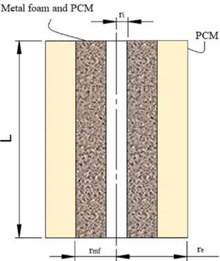
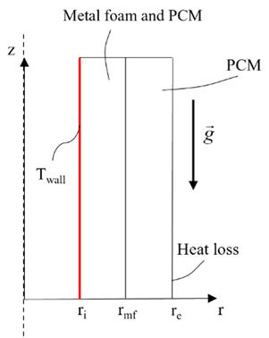
The LHTESS system is shown in Figure 1. It is a hollow cylinder. A planar section of the physical domain is shown in Figure 1a. As shown in Figure 1b, axial symmetry is assumed, and the two- dimensional problem is investigated. The height L is equal to 100mm, the internal radius ri is assumed equal to 6mm and the external radius re is 50mm. The gravitational acceleration g is directed along the z-axis. The internal surface of the hollow cylinder is assumed at a constant temperature above the melting temperature of the PCM. The assumed temperature is equal to 350K. The external top and bottom surfaces are assumed adiabatic. For the lateral surface a value of heat transfer coefficient (HTC) is set to model the heat loss of that surface. The initial temperature is set equal to 300K. Two ways to fill up the internal domain are considered. The system is partially filled by metal foam where the filling ratio is defined as:
$s=\frac{\left(r_{m f}-r_i\right)}{\left(r_e-r_i\right)}$ (1)
where, rmf is the metal foam interface radius. When the filling ratio s is not equal to zero it indicates that the domain is partially filled by pure PCM and metal foam region, where the pores are filled by PCM, that is indicate as MF. In this paper, it is assumed that the filling ratio is equal to 1/4 and 3/4.
(a)
(b)
Figure 1. LHTESS geometry: (a) planar section view; (b) axial symmetric view
To model the melting of the PCM the enthalpy-porosity method [14] is used. The Brinkman–Forchheimer-extended Darcy model and the local thermal equilibrium (LTE) hypothesis to describe the metal foam are assumed, as suggested by Buonomo et al. [16]. The following assumptions are made:
Following the previous assumptions, the governing equations are given by Buonomo et al. [16]. For the continuity equation it is:
$\frac{1}{r} \frac{\partial(r u)}{\partial r}+\frac{\partial w}{\partial z}=0$ (2)
where, the radial and axial velocity of the PCM in liquid phase are u and w respectively. Moreover, r, z are the coordinates of the cylindrical problem. Momentum equations:
$\frac{\rho_p}{\varepsilon}\left(\frac{\partial u}{\partial t}+\frac{u}{\varepsilon} \frac{\partial u}{\partial r}+\frac{w}{\varepsilon} \frac{\partial u}{\partial z}\right) u=-\frac{\partial p}{\partial r}+$$+\frac{\mu_p}{\varepsilon}\left(\frac{\partial^2 u}{\partial r^2}+\frac{1}{r} \frac{\partial u}{\partial r}-\frac{u}{r^2}+\frac{\partial^2 u}{\partial z^2}\right)+$
$-\frac{(1-\beta)^2}{\left(\beta^3+0.001\right)} A_{m u s h} u-\eta\left(\frac{\mu_p}{K} u+\frac{C_F}{\sqrt{K}} \rho_p u \sqrt{u^2+w^2}\right)$ (3)
$\frac{\rho_p}{\varepsilon}\left(\frac{\partial w}{\partial t}+\frac{u}{\varepsilon} \frac{\partial w}{\partial r}+\frac{w}{\varepsilon} \frac{\partial w}{\partial z}\right) u=-\frac{\partial p}{\partial r}$$+\frac{\mu_p}{\varepsilon}\left(\frac{\partial^2 w}{\partial r^2}+\frac{1}{r} \frac{\partial w}{\partial r}-\frac{u}{r^2}+\frac{\partial^2 w}{\partial z^2}\right)-\frac{(1-\beta)^2}{\left(\beta^3+0.001\right)} A_{m u s h} w$
$-\eta\left(\frac{\mu_p}{K} w+\frac{C_F}{\sqrt{K}} \rho_p w \sqrt{u^2+w^2}\right)+\rho_p g \gamma\left(T-T_0\right)$ (4)
where, the density and the specific heat of PCM are ρp and cp respectively. The viscosity of the liquid PCM is ρp the pressure is p. The mushy constant Amush value is assumed equal to 5x10⁵ kg m-3 s-1. Using the LTE assumption, the energy equation is:
$(\rho c)_{e f f}\left(\frac{\partial T}{\partial t}+u \frac{\partial T}{\partial r}+w \frac{\partial T}{\partial z}\right)=$$=k_{e f f}\left[\frac{\partial}{\partial r}\left(\frac{1}{r} \frac{\partial}{\partial r}(r T)\right)+\frac{\partial^2 T}{\partial z^2}\right]-\varepsilon \rho_P H_L \frac{\partial \beta}{\partial t}$ (5)
In Eq. (5) the PCM latent heat is HL whereas t is the time. Both the clean region (PCM) and porous medium region (MF) are applied to the momentum and energy Eqns. (3)-(5) by means of the following binary parameter:
$\eta(r, z)= \begin{cases}0 & \text { clean region }(\varepsilon=1) \\ 1 & \text { metal foam region }(0<\varepsilon<1)\end{cases}$ (6)
The effective thermal capacity (ρc)eff is equal to:
$(\rho c)_{e f f}=(1-\varepsilon) \rho_{m f} c_{m f}+\varepsilon \rho_P c_P$ (7)
where, ρmf and cmf represent the metal foam density and specific heat, respectively. The metal foam porosity is expressed by means of ε. Moreover, ρp and cp are the density and specific heat of PCM are indicated by, respectively. For the MF region, the effective thermal conductivity keff is equal to [17]:
$k_{e f f}=A\left[\varepsilon k_p+(1-\varepsilon) k_{m f}\right]+\frac{1-A}{\frac{\varepsilon}{k_p}+\frac{(1-\varepsilon)}{k_{m f}}}$ (8)
In Eq. (8) A is equal to 0.35 and in which kp and kmf are the thermal conductivities of PCM and aluminum foam, respectively.
In the following the permeability of the metal foam, K, as given in [18]:
$\frac{K}{d_p^2}=0.00073(1-\varepsilon)^{-0.224}\left(\frac{d_f}{d_p}\right)^{-1.11}$ (9)
Also, the Forchheimer coefficient, CF, is given by Calmidi et al. [18]:
$C_F=0.00212(1-\varepsilon)^{-0.132}\left(\frac{d_f}{d_p}\right)^{-1.63}$ (10)
The metal foam ligament diameter and the pore diameter, df and dp respectively, influence the permeability and the Forchheimer coefficient. These geometrical parameters describe the foam structure, and their ratio is equal to [18]:
$\frac{d_f}{d_p}=1.18 \sqrt{\frac{(1-\varepsilon)}{3 \pi}}\left(\frac{1}{1-(\mathrm{e})^{-((1-\varepsilon) / 0.04)}}\right)$ (11)
In this study, dp is assigned by the experimental values provided in references [17, 18].
The liquid fraction β is used to express the ratio between the liquid volume and the total volume of a cell of the mushy region in the enthalpy-porosity model. It has a value between 0 and 1. The local temperature in the cell influences the β value and in particular:
$\left\{\begin{array}{lll}\beta=0 & \text { for } & T<T_{\text {solidus }} \\ \beta=\frac{T-T_{\text {solidus }}}{T_{\text {liquidus }}-T_{\text {solidus }}} & \text { for } & T_{\text {solidus }}<T<T_{\text {liquidus }} \\ \beta=1 & \text { for } & T>T_{\text {liquidus }}\end{array}\right.$ (12)
where, the zone is totally solid β is 0, it is 1 where the zone is totally liquid. In Eq. (12) T, Tliquidus and Tsolidus are the local temperature value, the solid phase temperature, and the liquid phase temperature respectively. When the temperature is included between Tliquidus and Tsolidus the melting occurs. Whereases, the domain is fully solid where the temperature value is below Tsolidus, while the domain is fully liquid where that value is above the Tliquidus temperature. To take the model into account a source term in the momentum equation is added.
The chosen PCM is RT58 and the metal foam is made of aluminum. Table 1 summarizes the physical properties of RT 58 and aluminum metal foam. Its parameters are evaluated following the work of Battacharya et al. [17]. These parameters are summarized in Table 2.
Table 1. Physical properties
|
|
RT58 [19] |
Aluminum [20] |
|
Density [kg/m3] |
825 |
2719 |
|
Thermal conductivity [W/mK] |
0.2 |
202.4 |
|
Specific heat [J/kgK] |
2000 |
871 |
|
Dynamic viscosity [kg/m s] |
0.0269 |
|
|
Thermal expansion coeff. [K-1] |
0.00011 |
|
|
Latent heat [J/kg] |
160,000 |
|
|
Melting range [K] |
326-332 |
|
Table 2. Aluminum foam parameters
|
Porosity, ε |
0.95 |
|
Pore density, PPI |
20 |
|
df [m] |
0.0003 |
|
dp |
0.0027 |
|
CF |
0.093 |
|
K x107 [m2] |
1.3 |
|
keff [W/mK] |
3.42 |
The boundary conditions are no-slip between PCM liquid and walls, the isothermal condition on the surface of the internal cylinder is set, and the external top and bottom surfaces are assumed adiabatic. The lateral surface is set using a heat transfer coefficient to investigate its heat loss.
Heat losses and enthalpy as a function of time are given as:
$Q_{\text {loss }}=H T C \times 2 \pi r_e \int_0^L\left(T\left(r=r_e, z\right)-T_{e x t}\right) d z$ (13)
$\Delta H=\int_0^t\left(\left.2 \pi r_i k_{e f f} \int_0^L \frac{\partial T(r, z)}{\partial r}\right|_{r i} d z-Q_{\text {loss }}\right) d t$ (14)
The finite volume method is chosen. The governing equations are solved using the commercial code Ansys-Fluent [21]. SIMPLE algorithm for the pressure-velocity coupling and PRESTO algorithm for the pressure calculation are employed to perform the numerical simulations. Continuity and momentum equations convergence errors are set equal to 10−5, and for the energy equation the convergence error is set equal to 10−8.
A reference for the grid independence analysis is made to the work of Buonomo et al. [22], who used a geometry almost equal to the reported one. They verified, using the case where s is equal to 1/4 that among the three analyzed meshes, respectively made of 1540, 5964, 23124 cells the first two, which have a lower cost of calculation, present a modest difference both in terms of average temperature and of liquid fraction (less than 1%), and that especially the mesh with 1540 cells can be acceptable in terms of accuracy and costs of calculation. A time step analysis is, also, employed and a time step equal to 1s is chosen to perform the numerical investigation.
In this paper, two filling ratios are investigated: 1/4 and 3/4. For the filling ratio value equal to 1/4 are chosen three values of HTC: 0, which means an adiabatic condition on the lateral surface; 0.1, and 1. Whereas for the filling ratio value equal to 3/4 five values of HTC are chosen: 0, 0.1, 0.5, 1, 5.
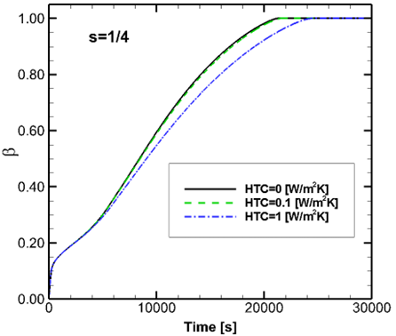
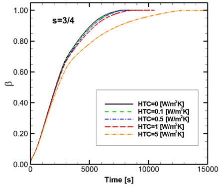
In Figure 2a is shown the time evolution of the average liquid fraction for s equal to 1/4, while in Figure 2b it is shown using the filling ratio value equal to 3/4. They show that the presence of metal foam significantly improves the heat transfer in the LHTES system giving a very faster phase change process with respect to the case with a lower value of filling ratio, reducing the melting time. When the HTC increases, the melting time increase.
(a)
(b)
Figure 2. Average liquid fraction evolution: (a) s=1/4; (b) s=3/4
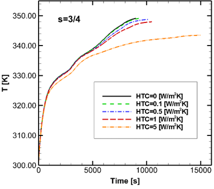
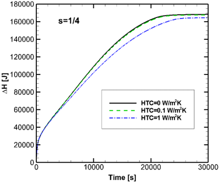
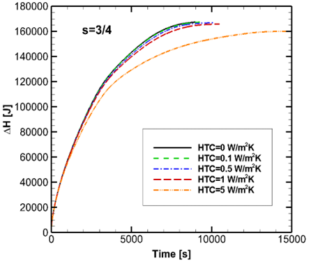
The reached equilibrium temperature, after that PCM has totally melted, decreases when HTC increases as is shown in Figure 3a and 3b. Consequently, the total energy value, given by Eq. (14), that is reached when the system has reached the thermal equilibrium, decreases as HTC increases as it is shown in Figure 4a and 4b. In Figure 4b it is important to underline that the system in the case with s equal to 3/4 reaches about 167 kJ at 9000 s, when its lateral surface is set adiabatic. Moreover, when HTC is equal to 5 it reaches about 150 kJ at 9000s and 160 kJ at 15000 s.
(a)
(b)
Figure 3. Average temperature evolution: (a) s=1/4; (b) s=3/4
(a)
(b)
Figure 4. Enthalpy evolution: (a) s=1/4; (b) s=3/4
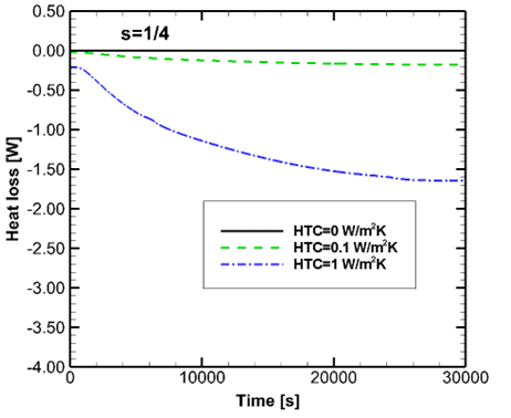
Figure 5a and 5b show the heat loss, given by Eq. (13), as a time function for the two filling ratio values chosen in this investigation at heat transfer coefficient variation. The initial heat loss value depends on the heat transfer coefficient and the imposed initial temperature difference between the system and ambient temperature. In the cases where the lateral surface is set adiabatic, the heat loss is zero during all the simulations. The heat loss increases when HTC increases. The maximum value of heat loss is equal to about 7 W when the HTC is equal to 5 for the system where the filling ratio value is equal to 3/4.
(a)
(b)
Figure 5. Heat loss evolution: (a) s=1/4; (b) s=3/4
This study intended to evaluate the effects of the heat loss on the lateral external surface of an LHTESS, composed of a high conductivity aluminum foam filled with RT58, during the charging phase. The metal foam had a pore density of 20 PPI and porosity equal to 0.95. The internal surface was assumed at a constant temperature above the melting temperature of PCM. Different external surface heat transfer coefficient values were set. The results showed how the different considered HTCs affected the heat transfer rate and described the trend of heat loss on the external surfaces, and how different values of the metal foam filling ratio affected the system behavior. Increasing the filling ratio value, the heat transfer in the whole system enhanced and the melting time was reduced. However, when the heat transfer coefficient increased, the heat loss increased, and the reached thermal equilibrium temperature was lower than the adiabatic case. The heat stored in the case for s=1/4 and HTC=5 Wm-2K-1 decreases of about 3% with respect to the adiabatic case. For the case with s=3/4 the decrease is about 6%. Moreover, the melting time increased when heat loss increased.
This research was funded by Ministero dell’Istruzione, dell’ Università e della Ricerca (MIUR), grant number PRIN-2017F7KZWS and by Università degli Studi della Campania “Luigi Vanvitelli” with the grant number D.R. n. 138 under NanoTES project - V: ALERE program 2020.
|
Acronyms |
|
|
LHTESS |
Latent Heat Thermal Energy Storage System |
|
LTE |
Local Thermal Equilibrium |
|
MF |
metal foam with voids filled with PCM |
| PCM | Phase Change Material |
|
PPI |
pore per inch |
|
TESS |
Thermal Energy Storage System |
|
Symbols |
|
|
(ρc)eff |
effective density and specific heat product, kg.m-3.J.kg-1.K |
|
Amush |
mushy zone constant |
|
c |
specific heat, J.kg-1.K-1 |
|
CF |
inertial drag coefficient |
|
df |
fiber diameter, m |
|
dp |
pore diameter, m |
|
H |
Height, m |
|
HL |
Latent heat of phase change material, J.kg-1 |
|
K |
Permeability, m2 |
|
keff |
effective thermal conductivity, W.m-1K-1 |
|
Q |
Heat losses, W |
|
r |
radial coordinate, m |
|
re |
external radius, m |
|
ri |
internal radius, m |
|
rmf |
metal foam radius, m |
|
rpcm |
PCM radius, m |
|
s |
filling ratio |
|
T |
temperature, K |
|
Tliquidus |
liquidus temperature, K |
|
Tsolidus |
solidus temperature, K |
|
Tw |
wall temperature, K |
|
u |
radial velocity, m.s-1 |
|
w |
axial velocity, m.s-1 |
|
z |
axial coordinate, m |
|
Greek symbols |
|
|
ΔH |
enthalpy variation, J |
|
β |
liquid fraction |
|
$\gamma$ |
thermal expansion coefficient, K-1 |
|
ε |
porosity of metal foam |
|
η |
binary parameter |
|
ρ |
density, kg.m-3 |
[1] Zhao, C., Opolot, M., Liu, M., Wang, J., Bruno, F., Mancin, S., Hooman, K. (2022). Review of analytical studies of melting rate enhancement with fin and/or foam inserts. Applied Thermal Engineering, 207: 118154. https://doi.org/10.1016/j.applthermaleng.2022.118154
[2] Fleischer, A.S. (2015). Thermal energy storage using phase change materials. Cham: Springer International Publishing, 20: 75-98. https://doi.org/10.1007/978-3-319-20922-7
[3] Fteïti, M., Nasrallah, S.B. (2004). Numerical analysis of a latent heat thermal energy storage system. International Journal of Heat and Technology, 22(Part A): 161-164. https://doi.org/10.1016/j.renene.2018.05.072
[4] Benbrika, M., Teggar, M., Benbelhout, M., Ismail, K.A.R. (2020). Numerical study of n-eicosane melting inside a horizontal cylinder for different loading rates. International Journal of Heat and Technology, 38(1): 125-130. https://doi.org/10.18280/ijht.380113
[5] Ahmadpour, V., Ahmadi, N., Rezazadeh, S., Sadeghiazad, M. (2013). Numerical analysis of thermal performance in a finned cylinder for latent heat thermal system (LHTS) applications. International Journal of Heat and Technology, 31(1): 155-162.
[6] Buonomo, B., Ercole, D., Manca, O., Nardini, S. (2016). Thermal behaviors of latent thermal energy storage system with PCM and aluminum foam. International Journal of Heat and Technology, 34(S2): S359-S364. https://doi.org/10.18280/ijht.34S224
[7] Chen, Y., Sun, Z., Zhou, J. (2014). Influence of additive NaCl on the phase-change heat transfer and storage capacity of NaNO3-KnO3 mixture. International Journal of Heat and Technology, 32(1): 23-26. https://doi.org/10.18280/ijht.320104
[8] Lachheb, M., Albouchi, F., Mzali, F., Nasrallah, S.B., Benameur, T. (2013). Thermal conductivty enhancement of LiNO3/graphite composite for energy storage. International Journal of Heat and Technology, 31(2): 9-16. https://doi.org/10.18280/ijht.310202
[9] Cabeza, L.F. (2021). Advances in Thermal Energy Storage Systems. Elsevier.
[10] Faraji, M., El Qarnia, H. (2008). Numerical optimization of a thermal performance of a phase change material-based heat sink. International Journal of Heat and Technology, 26(2): 17-24.
[11] Cammarata, G., Monaco, L., Cammarata, L., Petrone, G. (2013). A numerical procedure for PCM thermal storage design in solar plants. International Journal of Heat and Technology, 31(2): 105-110. https://doi.org/10.18280/ijht.310214
[12] Abdulmunem, A.R., Jabal, M.H., Samin, P.M., Rahman, H.A., Hussien, H.A. (2019). Analysis of energy and exergy for the flat plate solar air collector with longitudinal fins embedded in paraffin wax located in Baghdad center. International Journal of Heat and Technology, 37(4): 1180-1186. https://doi.org/10.18280/ijht.370428
[13] Oni, T.O., Awopetu, J.B., Adeleye, S.A., Uguru-Okorie, D.C., Adeyanju, A.A., Olukayode, N.E. (2021). Development of a latent heat thermal energy storage material-based refrigeration system. International Journal of Heat and Technology, 39(2): 469-476. https://doi.org/10.18280/ijht.390216
[14] Voller, V.R., Prakash, C. (1987). A fixed grid numerical modelling methodology for convection-diffusion mushy region phase-change problems. International Journal of Heat and Mass Transfer, 30(8): 1709-1719. https://doi.org/10.1016/0017-9310(87)90317-6
[15] Vafai, K. (2005). Handbook of Porous Media. CRC Press.
[16] Buonomo, B., Celik, H., Ercole, D., Manca, O., Mobedi, M. (2019). Numerical study on latent thermal energy storage systems with aluminum foam in local thermal equilibrium. Applied Thermal Engineering, 159: 113980. https://doi.org/10.1016/j.applthermaleng.2019.113980
[17] Bhattacharya, A., Calmidi, V.V., Mahajan, R.L. (2002). Thermophysical properties of high porosity metal foams. International Journal of Heat and Mass Transfer, 45(5): 1017-1031. https://doi.org/10.1016/S0017-9310(01)00220-4
[18] Calmidi, V.V., Mahajan, R.L. (2000). Forced convection in high porosity metal foams. Journal of Heat Transfer, 122(3): 1287793. https://doi.org/10.1115/1.1287793
[19] Dhaidan, N.S., Khalaf, A.F. (2020). Experimental evaluation of the melting behaviours of paraffin within a hemicylindrical storage cell. International Communications in Heat and Mass Transfer, 111: 104476. https://doi.org/10.1016/j.icheatmasstransfer.2020.104476
[20] Ji, C., Qin, Z., Dubey, S., Choo, F.H., Duan, F. (2018). Simulation on PCM melting enhancement with double-fin length arrangements in a rectangular enclosure induced by natural convection. International Journal of Heat and Mass Transfer, 127(Part A): 255-265. https://doi.org/10.1016/j.ijheatmasstransfer.2018.07.118
[21] ANSYS-FLUENT 2018. Computational Fluid Dynamic Code Version 19.2 User Guide.
[22] Buonomo, B., Manca, O., Nardini, S., Plomitallo, R.E. (2022). Numerical investigation on thermal behaviours of latent thermal energy storages with PCM partially filled with aluminum foam. Journal of Physics: Conference Series, 2177(1): 012014. https://doi.org/10.1088/1742-6596/2177/1/012014