Xinxin Ma | Fengshuang Zhang | Jianheng Sun*
© 2022 IIETA. This article is published by IIETA and is licensed under the CC BY 4.0 license (http://creativecommons.org/licenses/by/4.0/).
OPEN ACCESS
Problems such as carbonization, corrosion, and durability deterioration would occur to full-iron tailings reinforced concrete (FIT-RC) subjected to long-term use at high temperatures, to find solutions for these problems, it’s of important value to research the flexural performance of FIT-RC beam and its thermomechanical coupling mechanism. This paper proposed a calculation method for designing the flexural capacity and deflection of the normal section of FIT-RC beam, and summarized the high temperature relationship among thermal parameters, thermal stress, and thermal strain of FIT-RC material. In our experiment, four-point bending test was performed on the RC beams and the results showed that the bearing capacity of FIT-RC beam is equivalent to that of conventional reinforced concrete (CRC) beam, the failure modes of the two kinds of RC beams are basically the same. At high temperatures, the similarity of mechanical performance of concrete components with different reduction ratios is related to the similarity of temperature field. With the increase of heating time, the difference in the fire resistance grade of concrete components with different reduction ratios decreases to the minimum value. This study has clarified the high temperature relationship between thermal stress and thermal strain, and verified the feasibility of applying FIT to RC structures.
full-iron tailings reinforced concrete (FIT-RC), conventional reinforced concrete (CRC), beam, flexural performance, thermal stress, thermal strain
The fast industrialization process around the globe has increased the demand for iron products dramatically, which resulted in an increase in the production amount of iron tailings, a kind of industrial waste produced during the mineral separation and processing processes [1, 2]. The bulk accumulation of iron tailings often brings problems such as environmental pollution, land occupation, and landslides [3, 4]. Although there’re certain prevention and detection methods for the storage yards of tailings [5, 6], still, landslides occur from time to time, and the best solution to such problems is to develop and utilize iron tailings on a large scale. Concrete is one of the most widely used building materials, and the over-exploitation of its raw materials [7], sand and stone, can cause severe damages to rivers and mountains [8]. In this context, taking iron tailings as building materials has become a research hotspot for field scholars [9-11], and this could be a good way to solve the contradiction between resource exploitation and environmental conservation [12]. After subjected to high temperatures for a long time [13], carbonization, corrosion, and durability deterioration would occur to FIT-RC, which can threaten the engineering safety of the entire project [14]. Therefore, it is of important value to research the flexural performance of FIT-RC beam and its thermomechanical coupling mechanism.
Some scholars found that, after fine grinding, the powder of iron tailings can be used as a mineral admixture for concrete, for instance, Cheng et al. [15] investigated the effect of iron tailings powder on the compressive strength of concrete after the iron tailings has been subjected to mechanical and chemical activation, and the results showed that with the increase of the content of iron tailings powder, the compressive strength of concrete decreases; when a certain amount of water reducing agent is added and the content of iron tailings powder is kept within the range of 10%-40%, the concrete can meet the design requirement for compressive strength. Yang et al. [16] found that iron tailings exhibit the best activity when the specific surface area is between 450-550 m2/kg, and the maximum content does not exceed 30%; chemical activation has little effect on the activity of iron tailings, in contrast, mechanical activation is more economical and effective, and activity of iron tailings is higher than that of fly ash. Compared with fly ash, iron tailings mainly act as micro-aggregate fillers. Cheng et al. [17] studied the durability of iron tailings powder concrete, and the results suggest that as the replacement rate of iron tailings powder increases from 10% to 30%, the impermeability and frost resistance of concrete are enhanced, the carbonation resistance declines, but it can still meet the actual engineering requirements. Shettima et al. [18] used iron tailings sand to replace the river sand used in the concrete, and compared the prepared concrete with conventional concrete, and the results reveal that adding iron tailing sand can reduce the workability of concrete, the compressive strength and splitting tensile strength of the prepared concrete are better than those of conventional concrete. Zhang et al. [19] used iron tailings sand to replace the manufactured sand and studied the effect of replacement rate on the compressive strength and permeability of ultra-high performance mortar, the results prove that the performance of the mortar is the best when the replacement rate of iron tailings sand is 40%; at a replacement rate of 80%, there’s not much difference in the compressive strength between the prepared concrete and the control group concrete; as the replacement rate of iron tailings sand increases, the impermeability of the ultra-high performance mortar is enhanced.
Some scholars studied the mechanical performance of iron tailings as fine aggregates for concrete structures. For instance, Zhang [20] performed bending test on iron tailings sand concrete beam and ordinary concrete beam, and revised the formula of iron tailings sand concrete beam according to the calculation formula of the maximum crack width of ordinary concrete beam; the test results indicate that the stiffness of the iron tailings sand concrete beam is 1.1% lower than the standard stiffness, and the maximum crack width is 16% smaller than the standard crack width. Chen and Kuang [21, 22] replaced part of the fine aggregates with iron tailings sand to prepare green concrete, and compared its flexural properties with ordinary concrete, and the results demonstrated the two types of concrete beams have equivalent flexural properties; in the study, the calculation formulas of normal section flexural capacity, crack bending moment, and crack width refer to the GB 50010-2010 standards, but when the replacement rate of iron tailings exceeds 40%, the calculation of crack width needs to be corrected.
Developing and designing fire-resistant buildings is an effective way to prevent building fires. Makeeva et al. [23] studied the thermal stress of mass-volume concrete and RC structures during construction, analyzed the thermal stress of 1m-thick mass-volume concrete floor slabs, and solve the thermal stress problem of large foundation slabs during construction under the condition of not taking the temperature change into consideration. Ashkezari and Razmara [24] studied the thermal expansion coefficient, mass loss, and residual compressive strength of conventional concrete and ultra-high performance fiber reinforced concrete (UH-PFRC) at high temperatures, and the results showed that the thermal expansion coefficient of UH-PFRC is larger than that of conventional concrete, the mass loss of UH-PFRC is also greater than that of conventional concrete after heating, the compressive strength of all samples decreases with the increase of heating temperature.
Many scholars have tested and theoretically deduced the flexural performance of RC beams, analyzed the failure forms of the components, and established equations for calculating the bearing capacity of RC beams. However, few of them have taken iron tailings as admixtures or coarse and fine aggregates, or applied them to RC structures, and there’re few studies on the effect of temperature on the flexural performance of structures. So to fill in this research blank, this paper aims to explore the flexural performance of FIT-RC and its thermomechanical coupling mechanism, the main contents of this paper are: (1) Propose a method for calculating the bearing capacity and deflection of FIT-RC beams. (2) Summarize the high temperature relationship among thermal parameters, thermal stress, and thermal strain of the FIT-RC material. (3) Perform bending test on 4 RC beams using strain gauges pre-set in the beam structures and displacement meters set outside. Through the experiments, the flexural performance of FIT-RC beam was attained and its thermomechanical coupling mechanism was analyzed.
The first task of this paper is to propose an improved method for calculating the bearing capacity and deflection of FIT-RC beam, the calculation formula of the theoretical value of the crack bending moment of the beam (THEOcr) is:
$THE{{O}_{cr}}=\gamma \cdot {{f}_{t}}\cdot {{W}_{0}}$ (1)
where, ft represents the tensile strength of concrete; γ represents the plastic influence coefficient of the section resistance moment of concrete component, the rectangular section took the value of 1.55; W0 represents the elastic resistance moment of the tensile edge of the converted section, then it can be calculated by the following formula:
${{W}_{0}}={{I}_{0}}/(h-{{y}_{0}})$ (2)
where, I0 is the moment of inertia of the beam section, y0 is the distance from the barycenter axis of the converted section to the compressive edge, they can be calculated by the following formula:
${{I}_{0}}=(0.0833+0.19{{\alpha }_{E}}\rho )b{{h}^{3}}$ (3)
${{y}_{0}}=(0.5+0.425{{\alpha }_{E}}\rho )h$ (4)
where, αE represents the ratio of the elastic modulus of the rebar to the elastic modulus of the concrete; ρ represents the reinforcement ratio of longitudinal rebar calculated from the cross-sectional area of the concrete under tension; h represents the height of the beam.
The theoretical value of the yield bending moment THEOy of the beam can be calculated by the following formula [25]:
$THE{{O}_{y}}={{f}_{y}}{{A}_{s}}({{h}_{0}}-\frac{{{x}_{y}}}{3})$ (5)
${{f}_{y}}{{A}_{s}}=0.5{{\varepsilon }_{cm}}{{E}_{c}}b{{x}_{y}}$ (6)
$\frac{{{\varepsilon }_{cm}}}{{{\varepsilon }_{y}}}=\frac{{{x}_{y}}}{{{h}_{0}}-{{x}_{y}}}$ (7)
where, fy represents the yield strength of the rebar under tension; As represents the cross-sectional area of the rebar under tension; Ec represents the static elastic modulus of the concrete; b represents the width of the beam; xy represents the height of the concrete compression zone when the beam yields; εcm represents the average strain at the edge of the concrete compression zone; εy represents the yield strain of the longitudinal rebar; h0 represents the distance from the action point of the resultant force applied on the rebar under tension of the beam to the edge of the concrete.
At last, the theoretical limit bending moment value of the beam, THEOu, can be calculated by the following formula:
$THE{{O}_{u}}={{f}_{y}}{{A}_{s}}({{h}_{0}}-\frac{x}{2})$ (8)
$x=\frac{{{f}_{y}}{{A}_{s}}}{{{\alpha }_{1}}{{f}_{c}}b}$ (9)
where, x represents the height of the concrete compression zone when the beam is at its ultimate bearing capacity, it’s assumed that the beam is equivalent to a rectangular prism; α1 represents the strength coefficient of the concrete, its value takes 1.0; fc represents the axial compressive strength of the concrete.
The above is the calculation method of the theoretical value of the bearing capacity of RC beam. In the beam design and analysis process, the deflection control of the beam under normal use state is a very important indicator, and the deflection of RC beam can be calculated by the following formula:
$f=\frac{Pa{{l}^{2}}}{24{{B}_{s}}}(3-4{{\alpha }^{2}})$ (10)
where, P represents the load value; a represents the length of shear span; l represents the span, α represents the ratio of shear span to the span a/l; Bs represents the short-term stiffness of the beam after the component subjected to bending and cracks; then the initial stiffness before cracking Bscr can be calculated by the following formula:
${{B}_{s}}=\frac{{{E}_{s}}{{A}_{s}}h_{0}^{2}}{1.15\psi +0.2+6{{\alpha }_{E}}\rho }$ (11)
where, Es represents the elastic modulus of the rebar; ψ represents the strain non-uniformity coefficient of rebar between cracks under longitudinal tension, then it can be calculated by the following formula:
$\psi =1.1-0.65\frac{{{f}_{tk}}}{{{\rho }_{te}}{{\sigma }_{s}}}$ (12)
where, ftk represents the tensile strength of the concrete; ρte represents the reinforcement ratio of longitudinal rebar calculated from the effective cross-sectional area of the concrete under tension, and the effective cross-sectional area of the concrete under tension takes 0.5bh (namely ρte= fy As / 0.5bh).
The short-term stiffness Bs is applicable for flexural components after cracking, then the initial stiffness Bscr before cracking can be calculated by the following formula:
${{B}_{scr}}=0.85{{E}_{c}}{{I}_{0}}$ (13)
At high temperatures, a transient temperature field is formed on the section of the RC beam, and the mechanical performance of the FIT-RC will be affected by temperature. To reveal the similarity of the temperature field and mechanical response of RC at high temperatures, this study performed finite element simulation on the thermomechanical response of RC and made comparisons through continuous thermomechanical coupling. Assuming σIE and τIE are the density and specific heat capacity of the FIT-RC, then the volumetric heat volume of the FIT-RC is the product of σIE and τIE:
${{\sigma }_{IE}}{{\tau }_{IE}}=(0.005\delta +1.65)\times {{10}^{6}},0{}^\circ C\le \delta \le 180{}^\circ C$
${{\sigma }_{IE}}{{\tau }_{IE}}=2.68\times {{10}^{6}},180{}^\circ C\le \delta \le 380{}^\circ C$
${{\sigma }_{IE}}{{\tau }_{IE}}=(0.014\delta -2.55)\times {{10}^{6}},380{}^\circ C\le \delta \le 480{}^\circ C$ (14)
${{\sigma }_{IE}}{{\tau }_{IE}}=(-0.014\delta +9.8)\times {{10}^{6}},480{}^\circ C\le \delta \le 580{}^\circ C$
${{\sigma }_{IE}}{{\tau }_{IE}}=2.44\times {{10}^{6}},\delta >580{}^\circ C$
The peak specific heat capacity τmax corresponds to the temperature range from 100°C to 200°C. Assuming: ηSU represents the moisture content of the FIT-RC, then the peak specific heat capacity τmax under different moisture contents can be calculated by the following formula:
$\tau_{\max }=1885, \eta_{S U}<1.88 \%$
$\tau_{\max }=1885+(2800-1885)\left(\eta_{S U}-1.88 \%\right)(3.7 \%-2 \%)$
$1.88 \% \leq \eta_{S U}<3.7 \%$
$\tau_{\max }=2750+(5560-2800)\left(\eta_{S U}-3.7 \%\right)(9.7 \%-3.7 \%)$
$3.7 \% \leq \eta_{S U}<9.7 \%$
$\tau_{\max }=5560, \eta_{S U} \geq 9.7 \%$ (15)
The thermal conductivity of FIT-RC can be calculated by the following formula:
$\left\{ \begin{align}& {{\mu }_{p}}=-0.0009\delta +2,0{}^\circ C\le \delta \le 750{}^\circ C \\ & {{\mu }_{p}}=1.15,\delta >750{}^\circ C \\\end{align} \right.$ (16)
The thermal expansion coefficient of FIT-RC can be calculated as:
${{\beta }_{IE}}=(0.0079\delta +5.5)\times {{10}^{-6}}$ (17)
The volumetric heat volume σRE and τRE of the rebar can be calculated by the following formulas:
$\left\{ \begin{align} & {{\sigma }_{RE}}{{\tau }_{RE}}=(0.0035\delta +3.22)\times {{10}^{6}},0{}^\circ C\le \delta \le 680{}^\circ C \\ & {{\sigma }_{RE}}{{\tau }_{RE}}=(0.066\delta -35.5)\times {{10}^{6}},680{}^\circ C<\delta \le 780{}^\circ C \\ & {{\sigma }_{RE}}{{\tau }_{RE}}=(-0.079\delta +69.84)\times {{10}^{6}},780{}^\circ C<\delta \le 880{}^\circ C \\ & {{\sigma }_{RE}}{{\tau }_{RE}}=5.01\times {{10}^{6}},\delta >880{}^\circ C \\\end{align} \right.$ (18)
At high temperatures, the density of rebar does not change significantly, so the thermal conductivity of rebar can be calculated as:
$\left\{ \begin{align} & {{\mu }_{RE}}=-0.019\delta +55,0{}^\circ C\le \delta \le 880{}^\circ C \\ & {{\mu }_{RE}}=30.2,\delta >880{}^\circ C \\\end{align} \right.$ (19)
The thermal expansion coefficient of rebar can be calculated as:
${{\beta }_{RE}}=\left\{ \begin{align} & (0.0079\delta +5.5)\times {{10}^{-6}},\delta <880{}^\circ C \\ & 15.4\times {{10}^{-6}},\delta \ge 880{}^\circ C \\\end{align} \right.$ (20)
Assuming: gIE and ρIE are respectively the thermal stress and thermal strain of the FIT-RC; g’IE represents the axial compressive strength of the FIT-RC at high temperatures; ρmax represents the thermal strain corresponding to the peak thermal stress of the FIT-RC; g’IE0 represents the axial compressive strength of FIT-RC at room temperature; then at this time, the relationship between thermal stress and thermal strain of FIT-RC at high temperatures can be expressed as:
${{g}_{IE}}\left\{ \begin{align} & =g_{IE}^{'}\left[ 1-{{\left( \frac{{{\rho }_{\max }}-{{\rho }_{IE}}}{{{\rho }_{\max }}} \right)}^{2}} \right],{{\rho }_{IE}}<{{\rho }_{\max }} \\ & =g_{IE}^{'}\left[ 1-{{\left( \frac{{{\rho }_{IE}}-{{\rho }_{\max }}}{{{\rho }_{\max }}} \right)}^{2}} \right],{{\rho }_{IE}}>{{\rho }_{\max }} \\\end{align} \right.$ (21)
$g_{IE}^{'}\left\{ \begin{align} & =g_{IE0}^{'},\delta <450{}^\circ C \\ & =g_{IE0}^{'}\left[ 2.011-2.353\frac{\delta -20}{1000} \right],\delta \ge 450{}^\circ C \\\end{align} \right.$ (22)
${{\rho }_{\max }}=0.0025+(6\delta +0.04{{\delta }^{2}})\times {{10}^{6}}$ (23)
For the thermal stress-strain relationship of the rebar at high temperatures, assuming: before the rebar reaches the peak thermal strain ρBel, the elastic modulus of the rebar under tensile state is equal to the elastic modulus of the rebar under compressive state, then, the peak tensile thermal stress g’KL and the peak compressive thermal stress g’BE of the rebar satisfy:
$g_{KL}^{'}=0.0889g_{BE}^{'}$ (24)
At high temperatures, the thermal stress decreases linearly after the rebar reaches the peak strain ρBel. When the thermal strain of the rebar reaches 2ρBel, the corresponding stress of the rebar is 0.889g’KL and remains unchanged.
When the thermal strain ρCO of the rebar is lower than the peak thermal strain ρC, the linear relationship between the thermal stress and thermal strain of the rebar exhibits a constant slope. Therefore, the elastic modulus of the rebar at high temperatures is the secant modulus at ρCV. When ρCO is much larger than ρCV, the thermal stress of the rebar is linearly related to its thermal strain. Assuming: gb represents the thermal stress of the rebar; gb0 represents the yield strength of the rebar at room temperature, then they can be expresses as:
$\left\{ \begin{align} & {{g}_{b}}=\frac{g\left( \delta ,0.001 \right)}{0.001}{{\rho }_{CO}},{{\rho }_{CO}}\le {{\rho }_{CV}} \\ & {{g}_{b}}=\frac{g\left( \delta ,0.001 \right)}{0.001}{{\rho }_{CV}}+g\left[ \delta ,({{\rho }_{CO}}-{{\rho }_{CV}}+0.001) \right]-g\left( \delta ,0.001 \right), \\ & {{\rho }_{CO}}>{{\rho }_{CV}} \\\end{align} \right.$ (25)
${{\rho }_{CV}}=4\times {{10}^{6}}{{g}_{b0}}$ (26)
$\begin{align} & g\left( \delta ,0.001 \right)=\left( 50-0.04\delta \right) \\ & \text{ }\times \left\{ 1-\exp [(-30+0.03\delta )\sqrt{0.001}] \right\}\times 6.9 \\\end{align}$ (27)
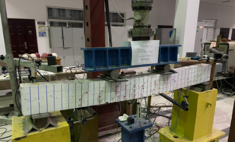
Figure 1. Four-point static bending test (unit: mm)
Figure 2. Test process
Raw materials used in our experiments include: P.O 42.5 ordinary Portland cement (produced by Beijing Jinyu Cement); grade-II fly ash with a specific surface area of 419 m2/kg, an apparent density of 2200 kg/m3, and an activity index of 0.71; finely ground iron tailings powder with a specific surface area 475.0 m2/kg, an apparent density of 2780 kg/m3, and an activity index of 0.70; iron tailings sand and river sand are both well-graded medium sand; both iron tailings and gravel are 5-20mm continuous grading; for grade-HRB400 rebar used in the experiment, 12mm rebar was used as longitudinal rebar under tension, 8mm rebar was used as stirrup rebar, and 6mm smooth rebar was used as erecting rebar. In the experiment, the concrete strength was set to C40, 3 FIT-RC beams and 1 CRC beam were designed and fabricated, the test equipment is shown in Figure 1 and the test process is shown in Figure 2.
In the 4-point bending test of RC beams, loads were applied on two pairs of symmetrical points, both the shear span length and the pure bending length of the RC beams were 600mm, a total of 5 displacement meters were set to measure the bending deflection; and strain gauges were arranged on the rebar and the concrete to measure the corresponding strain during loading. Table 1 gives the main indicators of concrete; Table 2 gives the mechanical properties of the rebar. Compared with CRC with same water-cement ratio, the compressive strength, axial compressive strength, splitting tensile strength, and elastic modulus of the FIT-RC cubes decreases by 11.7%, 5.8%, 3.0%, and 13.9%, respectively.
Table 1. Mechanical properties of concrete
|
Sample No. |
Cube crushing strength $f_{c u}^{0}$ /MPa |
Axial compressive strength $\boldsymbol{f}_{c}$ /MPa |
Splitting tensile strength $\boldsymbol{f}_{t}$ /MPa |
Static modulus of elasticity $\boldsymbol{E}_{c}$ /MPa |
|
FIT-RC |
48.4 |
35.6 |
3.2 |
3.21×10⁴ |
|
CRC |
54.8 |
37.8 |
3.3 |
3.73×10⁴ |
Table 2. Mechanical properties of rebar
|
Reinforcement diameter |
Yield strength $f_{y}$ /MPa |
Ultimate strength $f_{u}$ /MPa |
elastic modulus $\boldsymbol{E}_{s}$ /MPa |
Percentage elongation after fracture $\boldsymbol{\delta}$ /% |
|
6mm |
435 |
603 |
2.01×10⁵ |
17.3 |
|
8mm |
442 |
624 |
2.02×10⁵ |
17.8 |
|
12mm |
425 |
653 |
2.05×10⁵ |
19.9 |
Table 3. Load-carrying capacity of beams
|
Test piece |
Crack-resistant moment / kN·m |
Yield bending moment / kN·m |
Ultimate bending moment / kN·m |
||||||
|
Mcr |
THEOcr |
$\frac{M_{c r}}{T H E O_{c r}}$ |
My |
THEOy |
$\frac{M_{y}}{T H E O_{y}}$ |
Mu |
THEOu |
$\frac{M_{u}}{\mathrm{THEO}_{u}}$ |
|
|
FIT-RC-1 |
5.34 |
4.95 |
1.078787879 |
11.82 |
13.4 |
0.882089552 |
15.36 |
14.38 |
1.068150209 |
|
FIT-RC-2 |
5.1 |
4.95 |
1.03030303 |
13.2 |
13.13 |
1.005331302 |
14.91 |
14.38 |
1.036856745 |
|
FIT-RC-3 |
5.04 |
4.95 |
1.018181818 |
13.05 |
12.88 |
1.013198758 |
15.27 |
14.38 |
1.061891516 |
|
CRC |
5.04 |
4.96 |
1.016129032 |
13.62 |
12.65 |
1.076679842 |
16.53 |
14.45 |
1.143944637 |
Note: M- is the experimental result, and THEO- is the theoretical value.
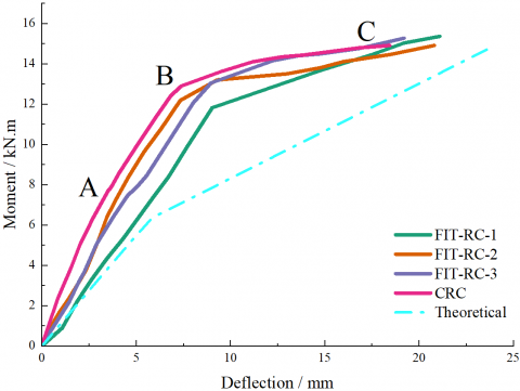
Figure 3. Relationship between moment and mid-span deflection of beams
Figure 3 shows the moment-deflection relationship of 3 FIT-RC beams and 1 CRC beam. The deflection was calculated from the displacement measured by the set displacement meters, and the bending moment was calculated from the vertical load. The curves of all beams can be divided into 3 stages from the initial stress state to the failure state.
The first stage is the elastic stage (section 0A), no crack develops during this stage, when the bending moment increases to the crack bending moment, cracks appear at the bottom of the beam [26], reducing the bending stiffness of the beam. The second stage is the crack development stage (section AB), during this stage, as the bending moment increases, the crack width gradually increases and the cracks develop upward, at a certain distance, new cracks would appear [27]. The third stage is the failure stage (section BC), during this stage, the tensile rebar yields and the bending moment reaches the yield bending moment. After the tensile rebar yields, the strain of the rebar increases significantly, crack develops and deflection increases, then, when the increment of bending moment is small, the deflection and crack width increase rapidly. At last, the beam structure fails due to the crushing of the concrete in the upper compression zone.
As can be seen from Figure 3, at each loading stage, the deflection of the FIT-RC beam is larger than that of CRC beam, which is consistent to the results shown in Table 3 that the elastic modulus of CRC is higher than that of FIT-RC. The theoretically calculated deflection values are shown in Figure 3. The actually measured deflection values of the RC beams are all smaller than the theoretical calculations, indicating that the calculation formula has a certain safety reserve in the RC beams and can be applied to the design of concrete structures.
Table 3 lists the bending moments of beam components at each stage, and compares the theoretical and measured values. The calculation of theoretical values in the table adopted the measured strength values of the concrete and the rebar, mainly including the axial compressive strength, the splitting tensile strength, and the elastic modulus of the concrete, and the yield strength of the rebar. For the four beam components FIT-RC-1, FIT-RC-2, FIT-RC-3 and CRC, the average strain εcm at the edge of the concrete compression zone is 0.000773, 0.000685, 0.000619, and 0.000567, respectively. According to the results in Table 3, the bearing capacity of the FIT-RC beams is comparable to that of the CRC beam. In addition, except for that the measured yield bending moment of FIT-RC-1 is smaller than the theoretical calculation, for other beam components, the ratios of the measured bending moment to the theoretical bending moment are all greater than 1 and less than 1.15. The theoretical calculation can well predict the bearing capacity of the RC beam components.
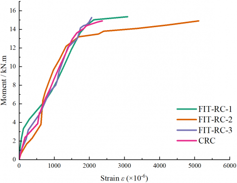
Figure 4. Relationship between bending moment and strain of rebar
Figure 5. Crack distribution of FIT-RC and CRC beams
Figure 4 shows the relationship between the bending moment and the strain of the longitudinal rebar under tension in the RC beams. Before and after the rebar yields, the strain curves of FIT-RC-1 and CRC basically overlap, therefore, although the tensile strength and elastic modulus of FIT-RC are lower than those of CRC, the adhesion of FIT-RC to rebar is not smaller than the adhesion of CRC to rebar. The bonding properties of concrete made of different materials with rebar are very good.
(a) Mid-span section strain of FIT-RC-1 beam
(b) Mid-span section strain of CRC beam
(c) Bending-shear section strain of FIT-RC-1 beam
(d) Bending-shear section strain of CRC beam
Figure 6. Concrete strain of beams
Figure 5 shows the crack distribution of beam components at the end of the tests. Cracks start from the pure bending zone, as the load increases, new cracks appear constantly and the existing cracks develop upward. When the load reaches a certain value, cracks develop along the shear direction. As can be seen from the figure, the failure modes of the FIT-RC beams and the CRC beam are similar. After the rebar yields, the concrete in the compression zone is crushed. No RC beam shows share failure.
For the three FIT-RC beams, the changes in the concrete with the change of load are similar. Figure 6 gives the typical concrete strain distribution. Because the bottom of the RC beams is subject to tension, and cracks cause the strain gauges attached to the concrete surface to fail prematurely, so only the strain distributions of loads near the concrete cracks are given here. It can be clearly seen from the figure that, regardless of pure bending section or shear bending section, under the action of the same bending moment, the concrete strain of the FIT-RC beam is greater than that of the CRC beam. As the load increases, the height of the concrete compression zone decreases. According to the figure, in each loading stage, the height of the concrete compression zone of FIT-RC beams is obviously smaller than that of the CRC beam, this is because the strength and elastic modulus of FIT-RC are lower than those of CRC.
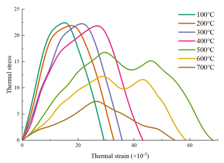
Figure 7. Relationship between thermal stress and thermal strain of concrete at high temperatures
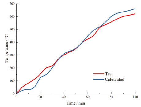
Figure 8. Temperature changes at measuring points on the cross-section of RC beams
Figure 9. Axial deformations of RC beams
(a)
(b)
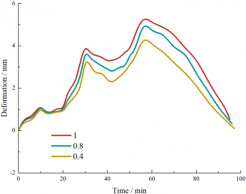
Figure 10. Curves of temperature and axial deformation of RC beams
Figure 7 shows the constitutive relationship between thermal stress and thermal strain of RC at high temperatures. Figures 8 and 9 show the temperature changes at each measuring point of the RC beam section and the deflections of the RC beam, respectively, and they compare the finite element results with the experimental values. It can be clearly seen that the temperature changes attained from finite element calculations are basically consistent with the measured results. When the temperature has continuously increased for 100 minutes, only the error of the calculated value at 55°C is a bit larger.
In addition, for the deflection, the error between results attained from finite element calculations and the measured values is greater, but its development trend is basically consistent with the temperature change curve. The calculated deflection and the measured deflection reach the maximum at 50-55 minutes. The above analysis shows that the simulation of the RC temperature field and mechanical performance has fully reflected the thermal stress-thermal strain response mechanism.
Figure 10 shows the curves of temperature and deflection of RC beams with a reduction ratio of 1, 0.8, and 0.4. According to Figure 10(a), the temperature curve of the RC beam with a reduction ratio of 1 is lower than that of other beams. In the first 5 minutes of heating, the temperatures of all beams rise quickly; when the heating time reaches 80 minutes, the changes of the beam temperature curves are significant; then when the heating time reaches 100 minutes, the temperature changes of the three curves are little. At high temperatures, the degree of similarity of mechanical performance of beams with different reduction ratios is related to the degree of similarity of temperature field. As can be seen in Figure 10(b), in the early stage of the axial compression of RC beams, for beams with smaller reduction ratios, the correlation is weaker. In the later stage, the similarity of temperature field between beams with different reduction ratios increases, when the heating time reaches 100 minutes, the difference in the fire resistance grade of beams with different reduction ratios reaches the minimum.
This paper studied the flexural performance of FIT-RC beam and its thermomechanical coupling mechanism. At first, this paper proposed a method for calculating the bending force bearing capacity and deflection of FIT-RC beam and calculated the corresponding values to perform theoretical analysis. Then, the paper summarized the thermal parameters of FIT-RC material, and clarified the high temperature relationship between thermal stress and thermal strain. At last, 4 RC beam components were fabricated and subjected to 4-point bending tests, through which the FIT-RC beams’ flexural performance was summarized and the thermomechanical coupling analysis results were given. The main conclusions are:
(1) Adding iron tailings as a raw material into concrete can reduce the strength and elastic modulus of concrete, and the decrease of elastic modulus was significant, reaching 13.9%;
(2) The bearing capacity of FIT-RC beams and CRC beam was comparable. The failure modes of the two kinds of RC beams were basically the same, in the end, both failed due to the yield of the tensile rebar and the crashing of concrete in the compression zone;
(3) Before cracking, the cross-sections of the FIT-RC and CRC beams were in good agreement with the assumptions, the design of the bearing capacity and deflection according to the calculation formulas provided by authors showed good safety;
(4) The temperature changes of the measuring points on the cross section of the RC beams, and the deflections of the RC beams were summarized. The results showed that the numerical simulation had fully verified the thermal stress-thermal strain response mechanism;
(5) Numerical simulations were carried out on the temperature change and deflection of RC beams with different reduction ratios, the results showed that at high temperatures, the degree of similarity of mechanical performance of beams with different reduction ratios was related to the degree of similarity of temperature field. As the heating time increased, the difference in the fire resistance grades of beams with different reduction ratios reached the minimum.
This work was supported by the Hebei Province Key Research and Development Project, China (Grant No.: 19211502D) and the Hebei Province Graduate Innovation Funding Project, China (Grant No.: CXZZBS2018109).
[1] Bian, Z., Miao, X., Lei, S., Chen, S.E., Wang, W., Struthers, S. (2012). The challenges of reusing mining and mineral-processing wastes. Science, 337(6095): 702-703. https://doi.org/10.1126/science.1224757
[2] Giri, S.K., Das, N.N., Pradhan, G.C. (2011). Magnetite powder and kaolinite derived from waste iron ore tailings for environmental applications. Powder Technol, 214(3): 513-518. https://doi.org/10.1016/j.powtec.2011.09.017
[3] Zhang, S., Xue, X., Liu, X., Duan, P., Yang, H., Jiang, T., Wang, D., Liu, R. (2006). Current situation and comprehensive utilization of iron ore tailing resources. Journal of Mining Science, 42(4): 403-408. https://doi.org/10.1007/s10913-006-0069-9
[4] Jamieson, H.E. (2011). Geochemistry and mineralogy of solid mine waste: Essential knowledge for predicting environmental impact. Elements, 7(6): 381-386. https://doi.org/10.2113/gselements.7.6.381
[5] Che, T.K., Pan, B.F., Sha, D., Lu, J.L. (2019). Utilization of iron tailings as fine aggregates in low-grade cement concrete pavement. IOP Conference Series: Materials Science and Engineering, 479(1): 012053. https://doi.org/10.1088/1757-899X/479/1/012053
[6] Mendes Protasio, F.N., Ribeiro de Avillez, Roberto., Letichevsky, S., de Andrade Silva, F. (2021). The use of iron ore tailings obtained from the Germano dam in the production of a sustainable concrete. Journal of Cleaner Production, 278: 123929. https://doi.org/10.1016/j.jclepro.2020.123929
[7] Ma, C. (2021). Physical properties and durability of green fiber-reinforced concrete for road bridges. Annales de Chimie Science des Materiaux, 45(1): 181-189. https://doi.org/10.18280/acsm.450211
[8] Zhao, T., Li, B.W., Gao, Z.Y., Chang, D.Q. (2010). The utilization of rare earth tailing for the production of glass-ceramics. Materials Science and Engineering: B, 170(1-3): 22-25. https://doi.org/10.1016/j.mseb.2010.02.019
[9] Zhao, F., Zhao, J., Liu, H. (2009). Autoclaved brick from low-silicon tailings. Construction and Building Materials, 23(1): 538-541. https://doi.org/10.1016/j.conbuildmat.2007.10.013
[10] Mun, K.J., Choi, N.W., So, S.Y., Soh, Y.S. (2007). Influence of fine tailings on polyester mortar properties. Construction and Building Materials, 21(6): 1335-1341. https://doi.org/10.1016/j.conbuildmat.2005.12.021
[11] Pan, H., Zhou, G., Cheng, Z., Yang, R., He, L., Zeng, D., Sun, B. (2014). Advances in geochemical survey of mine tailings project in China. Journal of Geochemical Exploration, 139: 193-200. https://doi.org/10.1016/j.gexplo.2013.07.012
[12] Ling, G., Shui, Z., Gao, X., Sun, T., Yu, R., Li, X. (2021). Utilizing iron ore tailing as cementitious material for eco-friendly design of ultra-high performance concrete (UHPC). Materials, 14(8): 1829. https://doi.org/10.3390/ma14081829
[13] Aljabbri, N.A.S., Hussein, M.N., Khamees, A.A. (2021). Performance of ultra high strength concrete expose to high rise temperature. Annales de Chimie Science des Materiaux, 45(4): 351-359. https://doi.org/10.18280/acsm.450411
[14] Bai, Y., Sun, J., Zhang, R. (2022). Bonding performance and thermomechanical coupling analysis of Iron ore tailings reinforced concrete. International Journal of Heat and Technology, 40(1): 193-200. https://doi.org/10.18280/ijht.400123
[15] Cheng, Y., Huang, F., Li, W., Liu, R., Li, G., Wei, J. (2016). Test research on the effects of mechanochemically activated iron tailings on the compressive strength of concrete. Construction and Building Materials, 118: 164-170. https://doi.org/10.1016/j.conbuildmat.2016.05.020
[16] Yang, M., Sun, J., Dun, C., Duan, Y., Meng, Z. (2020). Cementitious activity optimization studies of iron tailings powder as a concrete admixture. Construction and Building Materials, 265: 120760. https://doi.org/10.1016/j.conbuildmat.2020.120760
[17] Cheng, Y., Huang, F., Qi, S., Li, W., Liu, R., Li, G. (2020). Durability of concrete incorporated with siliceous iron tailings. Construction and Building Materials, 242: 118147. https://doi.org/10.1016/j.conbuildmat.2020.118147
[18] Shettima, A.U., Hussin, M.W., Ahmad, Y., Mirza, J. (2016). Evaluation of iron ore tailings as replacement for fine aggregate in concrete. Construction and Building Materials, 120: 72-79. https://doi.org/10.1016/j.conbuildmat.2016.05.095
[19] Zhang, W., Gu, X., Qiu, J., Liu, J., Zhao, Y., Li, X. (2020). Effects of iron ore tailings on the compressive strength and permeability of ultra-high performance concrete. Construction and Building Materials, 260: 119917. https://doi.org/10.1016/j.conbuildmat.2020.119917
[20] Zhang, L. (2012). Research on bending stiffness and crack of simply-supported beam of iron tailing concrete. Master's thesis, Southwest Jiaotong University, Chengdu, China.
[21] Chen, X. (2017). Experimental study on the mechanical properties of the iron tailing sand green concrete members. Doctor's thesis, Wuhan University of Technology, Wuhan, China.
[22] Kuang, Z. (2015). Experimental research on the flexural performance of concrete beams with mine tailings sand. Master's thesis, Zhengzhou University, Zhengzhou, China.
[23] Makeeva, A., Amelina, A., Semenov, K., Barabanshchikov, Y. (2018). Temperature action in analysis of thermal stressed state of massive concrete and reinforced concrete structures. MATEC Web of Conferences, 245: 03016. https://doi.org/10.1051/matecconf/201824503016
[24] Ashkezari, G.D., Razmara, M. (2020). Thermal and mechanical evaluation of ultra-high performance fiber-reinforced concrete and conventional concrete subjected to high temperatures. Journal of Building Engineering, 32: 101621. https://doi.org/10.1016/j.jobe.2020.101621
[25] Du, Y., Wang, J., Shi, C., Hwang, H., Li, N. (2021). Flexural behavior of alkali-activated slag-based concrete beams. Engineering Structures, 229: 111644. https://doi.org/10.1016/j.engstruct.2020.111644
[26] Zhao, N., Jiang, Y., Song, Y. (2021). Recognition and classification of concrete cracks under strong interference based on convolutional neural network. Traitement du Signal, 38(3): 1001-1007. https://doi.org/10.18280/ts.380338
[27] Paramanandham, N., Koppad, D., Anbalagan, S. (2022). Vision based crack detection in concrete structures using cutting-edge deep learning techniques. Traitement du Signal, 39(2): 485-492. https://doi.org/10.18280/ts.390210