Xutong Wang* | Meng Zhang
© 2021 IIETA. This article is published by IIETA and is licensed under the CC BY 4.0 license (http://creativecommons.org/licenses/by/4.0/).
OPEN ACCESS
The waste heat recovered by traditional industrial waste heat recovery systems is mostly high-temperature flue gas and combustible gas, while the waste heat of medium and low temperature flue gas that accounts for more than 50% of the total waste heat resources has been ignored, which is not conducive to the effective energy saving of industrial production and manufacturing process. In the meantime, few studies have concerned about the changes in the economy of circulating industrial waste heat recovery system. Therefore, to fill in this research gap, this paper aimed at the economy problem of circulating medium and low temperature industrial waste heat recovery system and carried out a series of research. The paper completed the thermodynamic analysis of different medium and low temperature waste heat recovery modes of industrial flue gas, and gave the analysis steps of the economy of circulating medium and low temperature waste heat recovery system of industrial flue gas. The effectiveness and accuracy of the thermodynamic and thermo-economic models constructed in the paper were proved by experimental results.
industrial waste heat recovery, circulating waste heat recovery, thermal economy
Energy is the material basis for human survival and the driving force for the development of national economy [1-4]. After the two industrial revolutions, the economy of human society began to develop at an accelerating speed, and the energy utilization modes are upgrading continuously. As a result, now all countries around the globe are facing two prominent problems: energy shortage and environmental pollution [5-9]. Due to the limited technological level and the historical problems of traditional industrial development mode, China's industrial production and manufacturing processes generally have problems such as high resource consumption and large energy waste. Therefore, China's industrial field has great energy-saving potential [10-14]. How to fully recover and utilize industrial waste heat on the premise of causing no disturbance to the original industrial production and manufacturing process has become a research focus for field scholars in the world [15, 16].
Waste heat recovery is an effective way to recycle energy. Loni et al. [17] summarized and discussed the research on waste heat recovery using Organic Rankine Cycle (ORC), and launched an investigation of the heat-electricity cogeneration system based on ORC. In view of the problem that the absorption heat pump and compression heat pump in traditional waste heat recovery systems cannot consider the temperature rise and efficiency, An et al. [18] proposed to use the thermally-coupled hybrid compression/absorption heat pump to achieve high-efficiency and high-temperature output; moreover, in order to fit in different scenarios, they also built a large temperature-rise cycle and a high-temperature output cycle, and constructed a mathematical model in ASPEN PLUS to predict the performance of the cycles. Based on the pinch analysis of a given heat exchange network, Wang et al. [19] proposed a systematic approach to integrate the heat pump into the industrial process, and analyzed the influence of waste heat temperature and temperature rise on the selection of heat pump; the proposed heat pump integration method can be further extended to other low-grade industrial waste heat recovery processes. Fito et al. [20] elaborated on how the selection of indicators changes the design of waste heat recovery system in district heating; then for three possible waste heat temperatures, they optimized the design, and the different optimizations were instructed by two energy indicators and the overall efficiency; after that, they evaluated the annual performance of the system using Sankey and Grassman diagrams, and gave a comparison of the optimized designs. Peris et al. [21] proposed to optimize the thermal economy of waste heat recovery systems based on experimental applications, they developed, calibrated, and verified a comprehensive facility model constructed based on actual operation data, this model could be applied to optimize the thermal economy, reveal the influence of the geometric parameters of organic fluid, circulation structure and main components, and formulate control strategies for obtaining the optimal cost-effective solution.
The waste heat recovered by traditional industrial waste heat recovery systems is mostly high-temperature flue gas and combustible gas. There’re quite a few problems with these systems such as low waste heat utilization rate, poor comprehensive utilization, and incomplete waste heat utilization equipment and system, also, the waste heat of medium and low temperature flue gas that accounts for more than 50% of the total waste heat resources has been ignored by these systems. Under the condition that the heat amount of the industrial waste heat recovery system is given, building a circulating system to pursue higher thermal efficiency is more reasonable, however, few studies have concerned about the changes in the economy of such circulating industrial waste heat recovery system. Therefore, to fill in this research gap, this paper attempts to study the economy of a circulating medium and low temperature waste heat recovery system (hereinafter referred to as “the circulating system” or “the proposed system”). The second chapter gives a thermodynamic analysis of different medium and low temperature waste heat recovery modes of industrial flue gas; the third chapter analyzes the economy of the circulating system; and the fourth chapter uses experimental results to verify the effectiveness and accuracy of the thermodynamic and thermo-economic models constructed in this paper.
2.1 Introduction to waste heat recovery modes
The waste heat of flue gas accounts for a large proportion in industrial waste heat, so making full use of the waste heat of industrial flue gas is one of the most important works in energy conservation. At first, this chapter starts from the thermodynamic point of view to give the general principle of waste heat recovery and utilization of industrial flue gas, and analyzes the grades of industrial flue gas of different temperature levels. Then, based on thermodynamic analysis, this chapter elaborates on the waste heat recovery and utilization modes of flue gas.
In order to achieve a high waste heat recovery and utilization efficiency of industrial flue gas, the following three aspects would require careful considerations: 1) The flue gas exergy value obtained by burning fuel at high temperature is greater; 2) Measures should be taken to try to reduce the heat loss caused by various irreversible losses such as heat transfer temperature difference, throttling, and friction; 3) Measures should be taken to comprehensively manage the coordination, conversion, and utilization of various energies in the system from the perspective of the overall energy system, thereby realizing multi-objective optimization of multiple factors such as heat, dynamics, control, economy and environmental protection.
As for the flue gas of different temperatures produced during industrial production process, the utilization modes differ as well. Table 1 lists the common temperatures and sources of industrial flue gas. In the table, the flue gas below 650℃ is defined as medium and low temperature flue gas, and the flue gas above 650℃ is defined as high temperature flue gas.
Table 1. Common temperatures and sources of industrial flue gas
|
Equipment |
High temperature |
Oxygen top-blown convertor |
Reverberatory furnace for copper smelting |
Nickel refinery furnace |
Zinc smelting furnace |
Conventional steel rolling heating furnace |
Furnace for dry-process cement production |
Glass melting furnace |
|
Temperature |
1650-1895 |
1120-1135 |
1450-1650 |
1010-1110 |
950-1250 |
650-850 |
700-950 |
|
|
Equipment |
Medium and low temperature |
Boiler |
Gas turbine |
Internal combustion engine |
Supercharged internal combustion engine |
Heat treatment furnace |
Drying furnace and arch furnace |
Heat exchanger |
|
Temperature |
120-320 |
450-550 |
350-650 |
300-450 |
420-620 |
300-620 |
330-480 |
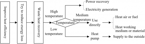
Figure 1. Recovery modes for waste heat of different temperature levels
Figure 1 shows the recovery modes for waste heat of different temperature levels. High temperature waste heat of industrial flue gas is often used for high temperature steam power recovery or electricity generation. Because the medium and low temperature waste heat of industrial flue gas has the characteristics of dispersed distribution, low heat transfer efficiency, and easy to cause waste, thus, strengthening the recovery and utilization of medium and low temperature waste heat of industrial flue gas is the key to improve the waste heat recovery rate from the perspective of the total energy system.
2.2 Thermodynamic analysis of different waste heat recovery modes
For the medium and low temperature waste heat of industrial flue gas, common utilization modes include: to heat air or fuel, to heat working medium, or to supply to the outside; details are described below:
In terms of the recovery mode of using medium and low temperature waste heat of industrial flue gas to heat air or fuel, the effective heat absorption of fuel heating equipment, working medium and materials is fixed, but the comburent air or fuel is heated by the recovered waste heat of flue gas, and it can be equivalent to that the amount of fuel supplied is reduced. Assuming: Eim represents the heat supplied to the outside before the recovery of medium and low temperature waste heat of industrial flue gas, Eim' represents the heat supplied to the outside after the recovery of medium and low temperature waste heat of industrial flue gas, Eba represents the effective heat absorbed by working medium and materials, Es represents the system heat loss before waste heat recovery, Es' represents the system heat loss after waste heat recovery, then, based on the principle of heat balance, the heat balance equation of the system before the recovery of medium and low temperature waste heat of industrial flue gas could be constructed, as shown in Formula 1:
${{E}_{im}}={{E}_{ba}}+{{E}_{s}}$ (1)
Under this recovery mode, the thermal efficiency of the system before the recovery of medium and low temperature waste heat of industrial flue gas could be calculated by Formula 2:
$\delta =\frac{{{E}_{ba}}}{{{E}_{im}}}\times 100{\scriptstyle{}^{0}/{}_{0}}$ (2)
Assuming: Eimr represents the among of heat recovered from medium and low temperature waste heat of industrial flue gas. Because the effective heat of the system before and after the recovery of medium and low temperature waste heat of industrial flue gas is fixed, Eimr satisfies equation E'im=Eim-Efr, then the heat balance equation of the system after the recovery of medium and low temperature waste heat of industrial flue gas is:
$E{{'}_{im}}=E{{'}_{ba}}+E{{'}_{s}}$ (3)
Under this recovery mode, the thermal efficiency of the system after the recovery of medium and low temperature waste heat of industrial flue gas could be calculated by Formula 4:
${{\delta }_{fr}}=\frac{{{E}_{ba}}}{E{{'}_{im}}}\times 100{\scriptstyle{}^{0}/{}_{0}}$ (4)
Formula 5 gives the calculation formula of energy-saving rate after waste heat recovery under this recovery mode:
$\sigma =1-\frac{\delta }{{{\delta }_{fr}}}=\frac{{{E}_{fr}}}{{{E}_{im}}}$ (5)
In terms of the recovery mode of using medium and low temperature waste heat of industrial flue gas to pre-heat or dry working medium or material, the heat is brought back to the equipment through the waste heat recovery of flue gas, this can also realize energy saving. Assuming: Ehi and Ehp respectively represent the system heat brought in and brought out by the working medium or material, then Formula 6 gives the heat balance equation of the system before the recovery of medium and low temperature waste heat of industrial flue gas under this recovery mode:
${{E}_{im}}={{E}_{ba}}+{{E}_{s}}={{E}_{hp}}-{{E}_{hi}}+{{E}_{s}}$ (6)
Under this recovery mode, the thermal efficiency of the system before the recovery of medium and low temperature waste heat of industrial flue gas could be calculated by Formula 7:
$\delta =\frac{{{E}_{ba}}}{{{E}_{im}}}\times 100{\scriptstyle{}^{0}/{}_{0}}$ (7)
Assuming: Efr represents the heat absorbed by the working medium or material in the recovery equipment after the recovery of medium and low temperature waste heat of industrial flue gas, Ehi'=Ehi+Efr represents the heat increment when it enters the equipment, then, it only needs to provide the amount of effective heat of Eba'=Eba-Efr to the working medium or material, and at this time, the heat supplied by air or fuel to the equipment is reduced from Eim to Eim'. Since the equipment is fixed, it can be considered that its processing load is fixed, then the following equation holds:
$\delta =\frac{{{E}_{ba}}}{{{E}_{im}}}\approx \frac{E{{'}_{ba}}}{E{{'}_{im}}}$ (8)
Since the effective heat of the system before and after the recovery of medium and low temperature waste heat of industrial flue gas is fixed, then, the heat balance equation of the system after waste heat recovery shown as Formula 9 holds:
$E{{'}_{im}}+{{E}_{fr}}={{E}_{ba}}+E{{'}_{s}}$ (9)
Under this recovery mode, the thermal efficiency of the system after the recovery of medium and low temperature waste heat of industrial flue gas could be calculated by Formula 10:
${{\delta }_{fr}}=\frac{{{E}_{ba}}}{E{{'}_{im}}}=\frac{{{E}_{ba}}-{{E}_{fr}}}{E{{'}_{im}}}\cdot \frac{{{E}_{ba}}}{{{E}_{ba}}-{{E}_{fr}}}=\delta \frac{1}{1-\frac{{{E}_{fr}}}{{{E}_{ba}}}}$ (10)
Formula 11 gives the calculation formula of energy-saving rate after waste heat recovery under this recovery mode:
$\sigma =1-\frac{\delta }{{{\delta }_{fr}}}=\frac{{{E}_{fr}}}{{{E}_{ba}}}$ (11)
In terms of the recovery mode of using the medium and low temperature waste heat of industrial flue gas to supply to the outside, the working process of the production equipment is not affected by it, but the heat loss of flue gas emission is effectively reduced due to waste heat recovery. Under this recovery mode, the heat balance equation after the recovery of medium and low temperature waste heat of industrial flue gas can be expressed as Formula 12:
${{E}_{im}}={{E}_{ba}}+{{E}_{fr}}+E{{'}_{s}}$ (12)
Under this recovery mode, the thermal efficiency of the system after the recovery of medium and low temperature waste heat of industrial flue gas could be calculated by Formula 13:
${{\delta }_{fr}}=\frac{{{E}_{ba}}+{{E}_{fr}}}{E{{'}_{im}}}=\delta +\frac{{{E}_{fr}}}{{{E}_{im}}}=\delta \left( 1+\frac{{{E}_{fr}}}{{{E}_{ba}}} \right)$ (13)
Formula 14 gives the calculation formula of energy-saving rate after waste heat recovery under this recovery mode:
$\sigma =1-\frac{\delta }{{{\delta }_{fr}}}=\frac{{{E}_{fr}}}{{{E}_{ba}}+{{E}_{fr}}}$ (14)
For the above three recovery and utilization modes of medium and low temperature waste heat of industrial flue gas, their energy-saving rates described by Formulas 5, 11 and 15 could be compared as:
$\frac{{{E}_{fr}}}{{{E}_{ba}}}>\frac{{{E}_{fr}}}{{{E}_{ba}}+{{E}_{fr}}}>\frac{{{E}_{fr}}}{{{E}_{im}}}$ (15)
Through above analysis, it can be known that, effective waste heat utilization usually transfers the waste heat to different media through various heat exchange equipment for reuse. Therefore, the effect of waste heat recovery and utilization is greatly influenced by the performance of heat exchange equipment.
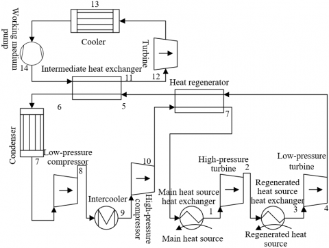
Figure 2. Flow of the trans-critical ORC system
The ORC system takes low boiling-point organics as working medium, its four core components are: waste heat boiler, turbine, working medium pump, and condenser; and its supporting system includes separator and regenerator. ORC system has simple structure and good economic performance. The research object of this paper is the 100℃~300℃ low-temperature flue gas discharged from industrial boilers, and using ORC system to recover the waste heat of this part of flue gas could achieve a good recovery effect. In this paper, a trans-critical ORC system with two-stage compression and two-stage expansion was constructed, and the flow of the system is given in Figure 2.
In the proposed system, at first the working medium absorbs heat from the main heat source and enters the high-pressure turbine for expansion work, then it is heated by the heat exchanger of the regenerated heat source, and enters low-pressure turbine for expansion work. The low-temperature working medium output from the high-pressure compressor is heated by the high-temperature working medium output from the low-pressure turbine through the regenerator, then, it enters the intermediate heat exchanger to release heat to the secondary circulating heat exchange working medium; after that, it is cooled by the condenser and compressed by the low-temperature compressor, and finally, it enters the heat exchanger of the main heat source through intermediate cooling and regeneration. This paper mainly analyzes the thermodynamics and thermal economy of the secondary circulating heat exchange process.
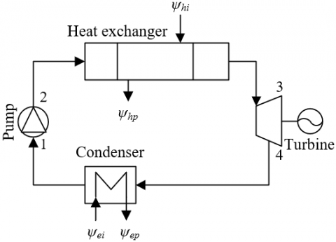
Figure 3. Structure of the secondary ORC system
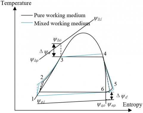
Figure 3 shows the structure of the secondary ORC system. In the figure, ψhi and ψhp respectively represent the inlet temperature and outlet temperature of flue gas; ψei and ψep respectively represent the inlet temperature and outlet temperature of cooling water; ψho represents the corresponding flue gas temperature at the pinch point of temperature difference of evaporator and condenser, and ψqo represents the corresponding cooling water temperature at this point; Δψw and Δψd respectively represent the pinch point temperature difference of evaporator and condenser. Figure 4 shows the temperature-entropy diagram of the secondary ORC system.
Figure 4. Temperature-entropy diagram of the secondary ORC system
According to the temperature of the medium and low temperature main heat source of industrial flue gas, this paper chose several organic working media such as candidate working media of the ORC system, including cyclohexane, n-ethane, pentane, and isopentane, etc. Table 2 lists the basic thermodynamic properties and environmental protection attributes of the candidate working media.
In the ORC system, the heat transfer process at the evaporator has two stages: preheating stage and evaporation stage. Assuming qh represents the mass flow of flue gas, qg represents the mass flow of working medium, ρoh represents the flue gas’s average specific heat capacity at constant pressure, ψh,n=(ψhi+ψhp)/2 represents the qualitative temperature, then, based on the law of energy conservation, there are:
${{E}_{w,pre}}={{q}_{h}}{{\rho }_{oh}}\left( {{\psi }_{ho}}-{{\psi }_{hp}} \right)={{q}_{g}}\left( {{f}_{5}}-{{f}_{2}} \right)$ (16)
${{E}_{w,eva}}={{q}_{h}}{{\rho }_{oh}}\left( {{\psi }_{hi}}-{{\psi }_{ho}} \right)={{q}_{g}}\left( {{f}_{3}}-{{f}_{5}} \right)$ (17)
$\Delta {{\psi }_{w}}={{\psi }_{ho}}-{{\psi }_{w}}$ (18)
Combining Formula 16, 17, and 18:
${{\psi }_{w}}=\frac{{{f}_{5}}-{{f}_{2}}}{{{f}_{3}}-{{f}_{2}}}{{\psi }_{hi}}+\frac{{{f}_{3}}-{{f}_{5}}}{{{f}_{3}}-{{f}_{2}}}{{\psi }_{ho}}-\Delta {{\psi }_{w}}$ (19)
Table 2. Basic thermodynamic properties and environmental protection attributes of candidate working media
|
Working medium |
Cyclohexane |
N-ethane |
Pentane |
Isopentane |
R123 |
R245fa |
|
Critical temperature |
281.3 |
235.4 |
189.2 |
185.2 |
183.4 |
156.7 |
|
Critical pressure |
4.065 |
3.052 |
3.26 |
3.39 |
3.645 |
3.612 |
|
Spontaneous combustion temperature |
- |
- |
265 |
423 |
Non-flammable |
- |
|
Security |
A3 |
A3 |
A3 |
B1 |
B1 |
A3 |
|
Ozone consumption potential |
0 |
1 |
0 |
0 |
0 |
0.013 |
|
Global warming potential |
0 |
0 |
12 |
0 |
962 |
125 |
Based on above formula, under the condition of a given set of (ψhi, ψhp, Δψw), the corresponding ψw can be obtained through iterations, further, the physical parameters of state points 3 and 5 in the cycle can be determined. Formula 20 gives the calculation formula of heat exchange in evaporator:
${{W}_{d}}={{q}_{g}}\left( {{f}_{3}}-{{f}_{2}} \right)={{q}_{h}}{{\rho }_{oh}}\left( {{\psi }_{hi}}-{{\psi }_{ho}} \right)$ (20)
The heat exchange area of the evaporator can be calculated by Formula 21:
${{S}_{d}}=\frac{{{E}_{d}}}{{{V}_{d}}\Delta {{\psi }_{d}}}$ (21)
Assuming: Vw represents the total heat transfer coefficient of the evaporator; fh represents the convective heat transfer system on the flue gas side, to simplify calculation, the Vw can be approximately equivalent to fh; NUN represents the Nusselt number; REN represents the Reynolds number; PRN represents the Prandtl number, then for the flue gas side, there is:
$NU{{N}_{h}}=0.27REN_{h}^{0.63}PRN_{h}^{0.36}$ (22)
Assuming: μh represents thermal conductivity of flue gas, Rw represents the outer diameter of evaporator pipe, then, Formula 23 gives the calculation formula of convective heat transfer coefficient of the flue gas side:
${{f}_{h}}=\frac{NU{{N}_{h}}\times {{\mu }_{h}}}{{{R}_{w}}}$ (23)
The heat exchange in the condenser can be calculated by Formula 24:
${{E}_{d}}={{q}_{g}}\left( {{f}_{4}}-{{f}_{1}} \right)={{q}_{e}}{{\rho }_{oe}}\left( {{\psi }_{ep}}-{{\psi }_{ei}} \right)$ (24)
Formula 25 gives the calculation formula of the heat exchange area of condenser:
${{S}_{d}}=\frac{{{E}_{d}}}{{{V}_{d}}\Delta {{\psi }_{d}}}$ (25)
Assuming: Rd represents the outer diameter of the condenser pipe, Edi represents the inner diameter of the condenser pipe, fe represents the heat transfer coefficient of water in the condenser pipe, fg represents the heat transfer coefficient of working medium outside the condenser pipe, then, the total heat transfer coefficient of the condenser can be calculated by Formula 26:
$\frac{1}{{{V}_{d}}}=\frac{{{R}_{d}}}{{{R}_{di}}{{f}_{e}}}+\frac{1}{{{f}_{g}}}$ (26)
As for the condenser, there is:
$NU{{N}_{e}}=0.023REN_{h}^{0.8}PRN_{h}^{0.4}$ (27)
Then, fe can be calculated by Formula 28:
${{f}_{e}}=\frac{M{{g}_{e}}\times {{\mu }_{e}}}{{{R}_{di}}}$ (28)
Assuming: μ1 represents the thermal conductivity of the liquid, φ1 represents the liquid density, φh represents the steam density, λ1 represents the dynamic viscosity of the liquid, ψd represents the average condensation temperature, ψy represents the pipe wall temperature, then, fg can be calculated by Formula 29:
${{f}_{g}}=0.725{{\left[ \frac{\beta h\mu _{1}^{3}{{\phi }_{1}}\left( {{\phi }_{1}}-{{\phi }_{h}} \right)}{{{\lambda }_{1}}{{R}_{d}}\left( {{\psi }_{d}}-{{\psi }_{y}} \right)} \right]}^{0.25}}$ (29)
Assuming: Δψmax and Δψmin respectively represent the maximum and minimum terminal temperature differences during the heat exchange process of heat exchanger, then Formula 30 gives the calculation formula of the logarithmic average temperature difference of evaporator and condenser:
$\Delta {{\psi }_{m}}=\frac{\Delta {{\psi }_{max}}-\Delta {{\psi }_{min}}}{ln\frac{\Delta {{\psi }_{max}}}{\Delta {{\psi }_{min}}}}$ (30)
The output work of the turbine can be calculated by Formula 31:
$D{{E}_{u}}={{q}_{g}}\left( {{f}_{3}}-{{f}_{4}} \right)$ (31)
The isentropic efficiency of the turbine can be calculated by Formula 32:
${{\delta }_{u}}=\frac{{{f}_{3}}-{{f}_{4}}}{{{f}_{3}}-{{f}_{4r}}}$ (32)
The power consumption of the working medium pump can be calculated by Formula 33:
$H{{E}_{QB}}={{q}_{g}}\left( {{f}_{2}}-{{f}_{1}} \right)$ (33)
The isentropic efficiency of the working medium pump can be calculated by Formula 34:
${{\delta }_{QB}}=\frac{{{f}_{2r}}-{{f}_{1}}}{{{f}_{2}}-{{f}_{1}}}$ (34)
The total investment cost of the ORC system includes four parts: evaporator, condenser, turbine, and working medium pump. If the system is equipped with additional equipment such as regenerator and separator, then the total investment cost is the sum of the input in the 6 parts, and Formula 35 gives the calculation formula of system investment cost:
$\lg {{D}_{IN}}={{\gamma }_{1}}+{{\gamma }_{2}}lg\omega +{{\gamma }_{3}}{{\left( lg\omega \right)}^{2}}$ (35)
Assuming: DIN represents the basic investment cost based on carbon steel structure and environmental pressure, ω represents the basic parameters of the cost of each component of the system, S represents the heat exchange area of corresponding heat exchanger, HEQB represents the consumed work of the pump, DE1 represents the output work of the turbine, Urw represents the capacity of the separator.
This paper adopted the standup-type gravity gas-liquid separator in the research, its capacity Urw can be calculated by the following steps. Assuming: φi and φh respectively represent the density of liquid and the density of gas corresponding to state points 4 and 2, ωr represents a constant coefficient, then, the gas flow rate in the gas-liquid separator can be calculated by Formula 36:
${{v}_{w}}=\frac{3}{4}\times {{\gamma }_{r}}\sqrt{\frac{{{\phi }_{1}}-{{\phi }_{h}}}{{{\phi }_{h}}}}$ (36)
Assuming: UMAX-h represents the maximum volume of the gas flow, q2 represents the mass flow of working medium at the turbine inlet, then, there is:
${{U}_{MAX\text{-}h}}=4800\times \frac{{{q}_{2}}}{{{\phi }_{h}}}$ (37)
Formula 38 gives the calculation formula of the cylinder diameter of the separator:
$Z{{J}_{rw}}=0.02\sqrt{\frac{{{U}_{h\text{ }max}}}{{{v}_{w}}}}$ (38)
Assuming γCS represents the pressure correction coefficient, and the pressure borne by components such as evaporator, regenerator and separator is uniformly represented by CS, then, based on above formula and the separator specification, the nominal volume of the separator can be further calculated:
$lg{{\gamma }_{CS}}={{D}_{1}}+{{D}_{2}}\lg CS+{{D}_{3}}{{\left( \lg CS \right)}^{2}}$ (39)
Assuming γCL and γSY respectively represent the material correction coefficient and the comprehensive correction coefficient, through correction, the system investment cost DSY can be updated as follows:
${{D}_{SY}}={{D}_{CS}}{{\gamma }_{SY}}={{D}_{CS}}\left( {{\alpha }_{1}}+{{\alpha }_{2}}{{\gamma }_{CL}}{{\gamma }_{CS}} \right)$ (40)
This paper mainly analyzes the performance of the ORC system from the perspective of thermal economy. In this paper, the heat exchange area required for unit net output power HEA, the turbine size FS, and the levelized electric energy cost FIP were selected as evaluation indicators of the economic performance of the circulating system; and the net output power DECL and the exergy efficiency δwa were selected as evaluation indicators of the thermodynamic performance of the circulating system. Assuming δuh represents the electric efficiency, then, Formula 41 gives the calculation formula of the system’s net output work DECL:
$D{{E}_{CL}}={{\delta }_{uh}}D{{E}_{u}}-D{{E}_{o}}$ (41)
The exergy efficiency δwa of the circulating system can be calculated by Formula 42:
${{\delta }_{wa}}=\frac{D{{E}_{CL}}}{T{{R}_{in}}-T{{R}_{out}}}$ (42)
HEA can be calculated by Formula 43:
$HEA=\frac{{{S}_{w}}+{{S}_{f}}+{{S}_{d}}}{D{{E}_{CL}}}$ (43)
Assuming RFu represents the volume flow of the fluid of working medium at turbine outlet, fIN and fOUT respectively represent the enthalpy at the turbine inlet and outlet, then, FS can be calculated by Formula 44:
$FS=\frac{\sqrt{R{{F}_{u}}}}{{{\left( {{f}_{IN}}-{{f}_{OUT}} \right)}^{0.25}}}$ (44)
According to above formula, the smaller the value of FS, the lower the investment cost of the system, and the better the economic performance of the system. Assuming SYW represents the system operation and maintenance cost, DOY represents the total annual system investment, then Formula 45 gives the calculation formula of the total investment of the circulating system Dtotal:
${{D}_{tot}}=D{{O}_{Y}}IRD+SYW$ (45)
Assuming ξ represents the bank interest rate, ε represents the normal operation life, then Formula 46 gives the calculation formula of the investment recovery factor IRD:
$IRD=\frac{\xi {{\left( 1+\xi \right)}^{\varepsilon }}}{{{\left( 1+\xi \right)}^{\varepsilon }}-1}$ (46)
The evaluation results of the thermal economic performance of the circulating system are greatly affected by the calculation results of various parameters such as the temperature of each state point, the mass fraction of the working medium, and dryness, etc. In this paper, the calculated results of the constructed thermodynamic model of the circulating system were compared with the actual measurement results of the waste heat recovery system under the external environmental conditions that are the same as the assumed conditions of the proposed system. Table 3 gives the comparison results, according to the table, the calculation results of the constructed model are basically the same with the actual measurement results, all errors are within the allowable range, which could verify the effectiveness and accuracy of the thermodynamic model constructed in this paper.
Table 3. Calculation results of the thermodynamic model of the circulating system
|
State point |
1 |
4 |
5 |
6 |
7 |
|
|
Temperature |
Calculation result |
115 |
117 |
43.25 |
112 |
45 |
|
Reference result |
112 |
114 |
42 |
118 |
/ |
|
|
Mass fraction of working medium |
Calculation result |
0.85 |
0.96523 |
0.95841 |
0.51241 |
0.52412 |
|
Reference result |
0.85 |
0.95 |
0.96 |
0.51 |
0.53 |
|
|
Dryness |
Calculation result |
0.6584 |
1 |
0.9568 |
0 |
0 |
|
Reference result |
0.69 |
1 |
0 |
3 |
1 |
|
|
State point |
10 |
11 |
12 |
13 |
14 |
|
|
Temperature |
Calculation result |
46.22 |
45.326 |
7 |
8.2651 |
63.254 |
|
Reference result |
45 |
48 |
8 |
7 |
62 |
|
|
Mass fraction of working medium |
Calculation result |
0.50241 |
0.82 |
0.81 |
0.83 |
0.85 |
|
Reference result |
0.5 |
0.54 |
0.81 |
0.86 |
0.84 |
|
|
Dryness |
Calculation result |
1 |
0 |
0.6254 |
0 |
0 |
|
Reference result |
1 |
0.96 |
0 |
1 |
1 |
|
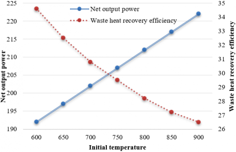
Figure 5. Curves of net output power and waste heat recovery efficiency of the circulating system
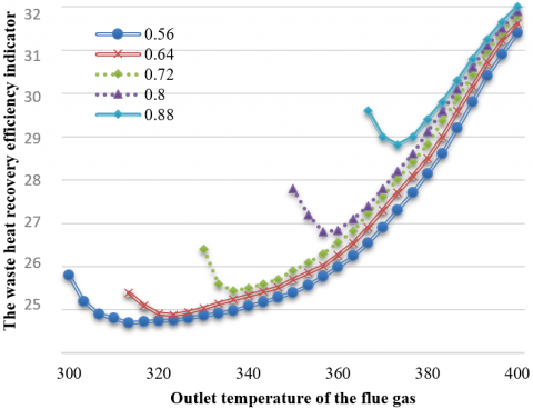
Figure 6. Curves of waste heat recovery efficiency under different working medium mass fractions
To evaluate the thermal economy of the proposed system more intuitively, this paper also calculated the main evaluation indicators of the thermal economy of the trans-critical ORC system, and Figure 5 gives the curves of the net output power and waste heat recovery efficiency of the circulating system under different initial temperatures, as can be seen from the figure, with the increase of the initial temperature of the main heat source, the net output power of the circulating system increases with it, while the corresponding waste heat recovery efficiency decreases with it.
Figure 6 shows the curves of waste heat recovery efficiency under different working medium mass fractions. According to the figure, the larger the mass fraction of the working medium, the higher the waste heat recovery efficiency of the system, and the better the thermal economic performance of the system. Under the condition of a same working medium mass fraction, the waste heat recovery efficiency of the system increases with the increase of the mass fraction of the working medium. Therefore, in order to ensure that the circulating system have a good thermal economic performance, when selecting the mass fraction of working medium, the value shouldn’t be too large or too small.
When selecting the recovery mode of medium and low temperature waste heat of industrial flue gas, on the premise that the benefit is ensured, we should try to make the initial temperature of the heat source as high as possible, so that the obtained exergy value of the flue gas is greater, the waste heat could be recovered as much as possible, and the fuel could be burned as fully as possible. In order to judge the influence of the initial temperature of heat source on the thermal economic benefit of waste heat recovery of the system, this paper gave relevant analysis from the perspective of energy. Table 4 gives the economic benefits of waste heat recovery under different initial temperatures of heat source; and Figure 7 shows the curves of the relationship between different initial temperatures of heat source and the annual recovery benefit, investment cost, and thermal economic benefit of the system.
Table 4. Economic benefits of waste heat recovery under different initial temperatures
|
Air preheating temperature (℃) |
110 |
120 |
130 |
140 |
150 |
160 |
|
Recovered heat (kw) |
322.26 |
358.16 |
395.14 |
430.26 |
466.25 |
502.16 |
|
Recovery benefit (yuan/year) |
270263.12 |
300145.29 |
330285.46 |
360295.27 |
390642.85 |
420361.84 |
|
Investment (yuan) |
88569.85 |
108253.85 |
132964.83 |
165343.65 |
210965.12 |
286135.68 |
|
Economic benefit (yuan/year) |
181602.87 |
192354.52 |
192548.85 |
195684.25 |
176849.35 |
136254.58 |
Figure 7. Changes of annual recovery benefit, investment cost, and thermal economic benefit of the system under different initial temperatures
According to Table 4 and Figure 7, with the increase of the initial temperature of heat source, the thermal economic benefit of the waste heat recovery of the circulating system exhibits a trend of increasing first and decreasing later, which is mainly due to the fast increase of investment cost of the circulating system, therefore, there’s an optimal initial temperature of the heat source to make the thermal economic benefit of waste heat recovery of the circulating system reach the optimum.
This paper studied the thermal economic performance of the medium and low temperature waste heat recovery system of industrial flue gas. At first, this paper gave thermodynamic analysis of the different recovery modes of medium and low temperature waste heat of industrial flue gas, then it also analyzed the thermal economy of the circulating system. The experimental results and the calculation results of the thermodynamic model of the circulating system verified the effectiveness and accuracy of the thermodynamic and thermo-economic models constructed in this paper. In addition, this paper also plotted the curves of the net output power and waste heat recovery efficiency of the circulating system, and the curves of waste heat recovery efficiency under different mass fractions of working medium, and the correlations were analyzed as well. After that, the paper discussed the thermal economic benefit under different initial temperatures of heat source, and analyzed the reason why the thermal economic benefit of waste heat recovery of the circulating system exhibits a trend of increasing first and decreasing later.
[1] Duan, X. (2017). Development of chemical energy and sustainable development of regional economy in Shaanxi province based on input-output theory. Chemical Engineering Transactions, 62: 571-576. https://doi.org/10.3303/CET1762096
[2] Xiao, Y., Wang, X., Wang, X., Wu, Z., Liu, W. (2017). The coordinated development path of renewable energy and national economy in China considering risks of electricity market and energy policy. IEEE Transactions on Industrial Informatics, 13(5): 2566-2575. https://doi.org/10.1109/TII.2017.2676814
[3] Chen, M., Sinha, A., Hu, K., Shah, M.I. (2021). Impact of technological innovation on energy efficiency in industry 4.0 era: Moderation of shadow economy in sustainable development. Technological Forecasting and Social Change, 164: 120521. https://doi.org/10.1016/j.techfore.2020.120521
[4] Wu, H., Peng, D., Wang, L. (2021). Model for sustainable development based on system dynamics and energy–economy–environment coordination: A case study of Beijing, China. Energy Science & Engineering, 9(6): 828-842. https://doi.org/10.1002/ese3.837
[5] Buko, J., Duda, J., Makowski, A. (2021). Food production security in times of a long-term energy shortage crisis: The example of Poland. Energies, 14(16): 4725. https://doi.org/10.3390/en14164725
[6] Sun, C., Hui, J. (2020). Analysis of pollutant emission characteristics of marine diesel engine using chemical kinetics under the background of energy shortage. Journal of Physics: Conference Series, 1549(2): 022010. https://doi.org/10.1088/1742-6596/1549/2/022010
[7] Wang, S., Wang, X., Fu, Z., Liu, F., Xu, Y., Li, W. (2022). A novel energy-water nexus based CHP operation optimization model under water shortage. Energy, 239: 121832. https://doi.org/10.1016/j.energy.2021.121832
[8] Aljendy, R.I., Nasyrov, R.R., Tulsky, V.N., Sultan, H.M. (2019). Optimal installed capacity of renewable energy sources for active power shortage minimization. 2019 International Ural Conference on Electrical Power Engineering (UralCon), Chelyabinsk, Russia, pp. 349-354. https://doi.org/10.1109/URALCON.2019.8877659
[9] Xing, X., Yan, Y., Zhang, H., Long, Y., Wang, Y., Liang, Y. (2019). Optimal design of distributed energy systems for industrial parks under gas shortage based on augmented ε-constraint method. Journal of Cleaner Production, 218: 782-795. https://doi.org/10.1016/j.jclepro.2019.02.052
[10] Xu, M., Lin, B., Wang, S. (2021). Towards energy conservation by improving energy efficiency? Evidence from China’s metallurgical industry. Energy, 216: 119255. https://doi.org/10.1016/j.energy.2020.119255
[11] Wang, X., Li, Z., Shaikh, R., Ranjha, A.R., Batala, L.K. (2021). Do government subsidies promote financial performance? Fresh evidence from China's new energy vehicle industry. Sustainable Production and Consumption, 28: 142-153. https://doi.org/10.1016/j.spc.2021.03.038
[12] Wu, R., Lin, B. (2021). Does industrial agglomeration improve effective energy service: An empirical study of China’s iron and steel industry. Applied Energy, 295: 117066. https://doi.org/10.1016/j.apenergy.2021.117066
[13] Wang, N., Zhang, W., Fu, Y. (2021). Decomposition of energy intensity in China’s manufacturing industry using an agglomeration extended LMDI approach. Energy Efficiency, 14(7): 66. https://doi.org/10.1007/s12053-021-09968-7
[14] Li, J. (2020). Charging Chinese future: the roadmap of China's policy for new energy automotive industry. International Journal of Hydrogen Energy, 45(20): 11409-11423. https://doi.org/10.1016/j.ijhydene.2020.02.075
[15] Shahzad, M.K., Ding, Y., Xuan, Y., Gao, N., Chen, G. (2021). Energy efficiency analysis of a multifunctional hybrid open absorption system for dehumidification, heating, and cooling: An industrial waste heat recovery application. Energy Conversion and Management, 243: 114356. https://doi.org/10.1016/j.enconman.2021.114356
[16] Gao, W., Zhou, Y.H., Zhang, L.W., Wang, Y.F. (2020). Design and optimization of industrial low-grade waste heat recovery for multi-period cooling. Journal of Chemical Engineering of Chinese Universities, 34(6): 1520-1526. http://dx.chinadoi.cn/10.3969/j.issn.1003-9015.2020.06.024
[17] Loni, R., Najafi, G., Bellos, E., Rajaee, F., Said, Z., Mazlan, M. (2021). A review of industrial waste heat recovery system for power generation with Organic Rankine Cycle: Recent challenges and future outlook. Journal of Cleaner Production, 287: 125070. https://doi.org/10.1016/j.jclepro.2020.125070
[18] An, M., Zhao, X., Xu, Z., Wang, R. (2021). A hybrid compression absorption high temperature heat pump cycles for industrial waste heat recovery. Journal of Shanghai Jiaotong University, 55(4): 434. https://doi.org/10.16183/j.cnki.jsjtu.2020.023
[19] Wang, M., Deng, C., Wang, Y., Feng, X. (2020). Exergoeconomic performance comparison, selection and integration of industrial heat pumps for low grade waste heat recovery. Energy Conversion and Management, 207: 112532. https://doi.org/10.1016/j.enconman.2020.112532
[20] Fito, J., Hodencq, S., Ramousse, J., Wurtz, F., Stutz, B., Debray, F., Vincent, B. (2020). Energy-and exergy-based optimal designs of a low-temperature industrial waste heat recovery system in district heating. Energy Conversion and Management, 211: 112753. https://doi.org/10.1016/j.enconman.2020.112753
[21] Peris, B., Navarro-Esbrí, J., Mateu-Royo, C., Mota-Babiloni, A., Molés, F., Gutiérrez-Trashorras, A.J., Amat-Albuixech, M. (2020). Thermo-economic optimization of small-scale Organic Rankine Cycle: A case study for low-grade industrial waste heat recovery. Energy, 213: 118898. https://doi.org/10.1016/j.energy.2020.118898