Yi Zhang | Qinjing Wu* | Wei Hu
© 2021 IIETA. This article is published by IIETA and is licensed under the CC BY 4.0 license (http://creativecommons.org/licenses/by/4.0/).
OPEN ACCESS
The electricity transactions of microgrids face several problems: the high platform management cost, the low security, and the untimely consumption of scattered electricity. To solve these problems, this paper presents a multi-microgrid thermal game model based on quantum blockchain. Specifically, a dynamic model was established for the noncooperative game between aggregators, microgrids, and large users to maximize the benefit of each party, and to realize the timely consumption of scattered electricity. Next, a transaction platform was constructed based on the two-round password based authenticated key exchange (PAKE) protocol, which eliminates non-interactive zero-knowledge (NIZK), aiming to substantially enhance the post-quantum security of transactions. Then, the quantum signature using two-particle entangled Bell states was adopted to safeguard the quantum communication of electricity transactions, and authenticate the nodes. Example analysis shows that our model can realize the timely consumption of scattered electricity and thermal energy, improve the security of transaction data and users, and achieve Pareto optimality. The research provides theoretical support and decision-making basis for electricity transactions in the post-quantum age.
quantum block chain, multiple microgrids, noncooperative game, electricity transaction, thermal energy
With the rapid transformation of traditional energy to intelligent energy, the marketization of electricity transaction is picking up speed. Multiple distributed energy sources are being widely used in microgrids and regional integrated energy systems [1]. Microgrids play an important role in optimizing resource allocation for integrated energy applications. However, the transactions in the current energy Internet face several problems: the high cost of centralized management, proneness to attacks, poor security of user information, and dispersion of residual electricity of microgrids. The key to solve the above problems is to establish a highly secure, low cost, decentralized transaction platform. Besides, third-party agents should be introduced to collect the scattered electricity, and promote the local consumption of dispersed renewable energy [2]. As a decentralized distributed database [3], the blockchain can facilitate the collaboration between the traders of various energy, and support diverse and reliable management of the transactions in the electricity market.
To date, many domestic and foreign scholars have discussed the application scenarios of the blockchain in energy transactions. Zhang et al. [4] specified the application modes of blockchain in energy Internet under multiple scenarios, including the authentication of carbon emission rights, the security of information physical systems, the transactions of virtual generation resources, and the collaboration between multiple energy systems. Li et al. [5] designed an energy blockchain transaction mode based on credit bank. Thakur and Breslin [6] developed a blockchain-based energy transaction mode between microgrids, trying to increase the utilization rate of renewable energies, and lower line loss. Based on the consensus mechanism of proof of stake (PoS), Gong et al. [7] verified the applicability of blockchain in integrated energy services. Shen et al. [8] explored the applicability of three types of blockchains, namely, public chain, alliance chain, and private chain, in the energy field, and demonstrated the four application scenarios and engineering cases of blockchain in that field.
Relying on blockchain, the above studies have formulated decentralized model frameworks, and constructed basic electricity transaction models. However, none of them tackle the electricity consumed by scattered microgrids, or take effective measures to safeguard transaction security and user privacy, although blockchain security is generally threatened by the rapidly developing quantum information technology.
Considering the above, this paper proposes a multi-microgrid game model based on quantum blockchain. Firstly, a dynamic model was established for the noncooperative game between aggregators, and between microgrids and aggregators, aiming to maximize the benefit of distributed energy. Next, an electricity transaction platform was set up based on quantum blockchain. Then, the authors adopted the two-round password based authenticated key exchange (PAKE) protocol, which takes basis on smart contract and eliminates non-interactive zero-knowledge (NIZK), as well as quantum signature to substantially increase transaction security, lower the transaction cost of the platform, and safeguard user privacy. In this way, the users of aggregators and electricity-demanding large users can realize flexible transactions.
The blockchain is a tamper-proof, and unforgeable distributed database, which is open, transparent, and decentralized [9]. Blockchain-based transactions require no third-party supervision, which greatly reduces the management cost. Besides, the distributed storage mode lowers the purchase cost of servers, and ensures the security and transparency of data [10]. The basic structure of the blockchain is given in Figure 1. Each block consists of a header and a body. The header contains the hash value of the previous head, and the body mainly records the transaction information, code information, and state information [11]. The header and the body are connected by the Markle root, making it easy to quickly sum up and verify the correctness and completeness of transactions [12].
In quantum blockchain, the information in each block is encoded as a string of entangled photons [13]. The blocks are connected to each other in the chronological order of entanglement. When the blocks of quantum blockchain are transmitted in the network of quantum computers, every photon generated for encoding the block information is absorbed by the network nodes [14, 15], and the previous photons cannot be modified. Therefore, quantum blockchain further improves the tamper-proofness and security of information from the level of the traditional blockchain.
Figure 1. Basic structure of blockchain
This paper proposes a CCHE supply system, which combines cooling, heating, electricity storage, and electricity supply. Compared with the traditional cointegration system, the CCHE supply system adds the electricity supply mode to improve the recycling efficiency of energy, and realize the multistage utilization of energy. The CCHE supply system is composed of the electricity purchase by microgrids from aggregators, distributed electricity generators, cold and heat energy conversion devices, and CCHE system. In the microgrids, distributed electricity generators are adopted, including wind turbines and photovoltaic (PV) generators, and the electricity is generated by driving the marine gas turbine (MT) with natural gas. During the summer, ice storage air conditioners are used to cool the air, while storing the energy. During the winter, boilers are utilized to generate heat, and recycle and store the waste heat.
The power output of a microgrid can be expressed as:
${{P}_{E}}={{P}_{M-A}}+{{P}_{MT}}+{{P}_{REG\_self}}+{{P}_{CCHE}}$ (1)
where, $P_{M-A}$ is the amount of electricity purchased by the microgrid from aggregators; $P_{M T}$ is the amount of electricity generated by the MT; $P_{R E G_{-} \text {self }}$ is the amount of electricity generated by the distributed generators in the microgrid; $P_{C C H E}$ is the energy converted from energy storage, and cooling/heating. Among them, $P_{M T}$ and $P_{R E G_{-} \text {self }}$ can be calculated by:
$\left\{ \begin{align} & {{p}_{MT}}={{\eta }_{MT}}\cdot {{V}_{MT}}\cdot {{L}_{MT}} \\ & {{p}_{REG}}={{p}_{WT}}+{{p}_{PV}} \\\end{align} \right.$ (2)
where, $\eta_{M T}$ is the electricity conversion efficiency of $\mathrm{MT} ; L_{M T}$ is the low calorific value of MT; $p_{W T}$ is the amount of electricity generated by distributed wind turbines; $p_{P V}$ is the amount of electricity generated by distributed PV generators.
3.1 CCHE system
The CCHE system includes an electricity storage device, a cooling/heating device, and an energy conversion device. The electricity storage device mainly encompasses batteries. The cooling and conversion device is an ice storage air conditioner. The heating and waste heat recovery devices are boilers and heat storage pools.
3.1.1 Battery output
Considering peak-load shifting, the batteries store electricity during the valley hours and sell electricity during the peak hours, aiming to maximize the benefit. The relevant constraints are given in formulas (3)-(6).
Charge/discharge constraint:
$\left\{ \begin{matrix} U_{BT,cha}^{t}\cdot P_{BT,cha,\min }^{t}\le P_{BT,cha}^{t}\le U_{BT,cha}^{t}\cdot P_{BT,cha,\max }^{t} \\ U_{BT,dis}^{t}\cdot P_{BT,dis,\min }^{t}\le P_{BT,dis}^{t}\le U_{BT,dis}^{t}\cdot P_{BT,dis,\max }^{t} \\\end{matrix} \right.$ (3)
State of charge (SOC) constraint:
$\left\{ \begin{matrix} E(t)=E(t-1)+(P_{BT,cha}^{t}\cdot {{\eta }_{BT,cha}}-\frac{P_{BT,dis}^{t}}{{{\eta }_{BT,dis}}})\cdot \Delta T \\ 0.2{{E}_{BT,\max }}\le E(t)\le 0.8{{E}_{BT,\max }} \\\end{matrix} \right.$ (4)
where, $U_{B T, \text { cha }}^{t}$ and $U_{B T, \text { dis }}^{t}$ are the marker bits for the charge state and discharge state, respectively; $P_{B T, \text { cha,min }}^{t}$ and $P_{B T, \text { cha,max }}^{t}$ are the minimum and maximum power of the battery during charge, respectively; $P_{B T, d i s, \min }^{t}$ and $P_{B T, d i s, \max }^{t}$ are the minimum and maximum power of the battery during discharge, respectively; $P_{\text {cha }}^{t}$ and $P_{\text {dis }}^{t}$ are the charge and discharge power of the battery, respectively; $E(t)$ is the residual power of the battery; $\Delta T$ is the time interval in dayahead plan; $\eta_{B T, \text { cha }}$ and $\eta_{B T, \text { dis }}$ are the charge and discharge efficiency coefficients of the battery, respectively; $E_{B T, \max }$ is the maximum capacity of the battery. The charge and discharge states of the battery are marked by 0 and 1, respectively [16].
In addition, the battery needs to satisfy the following constraints:
$U_{B T, \text { cha }}^{t}+U_{B T, \text { dis }}^{t} \leq 1$
(mutually exclusive constraint)
$\sum_{T=1}^{24}\left(U_{B T, \text { cha }}^{t}+U_{B T, \text { dis }}^{t}\right) \leq T$
(charge / discharge frequency constraint)
$E(0)=E(24)$
(constraint on the relationship between start time charge and end time charge of each day) (5)
The charge/discharge rate of the battery depends on the ramp rate, which is constrained by:
$\left\{ \begin{matrix} P_{BT,cha}^{down}\le P_{BT,cha}^{t}-P_{BT,cha}^{t-1}\le P_{BT,cha}^{up} \\ P_{BT,dis}^{down}\le P_{BT,dis}^{t}-P_{BT,dis}^{t-1}\le P_{BT,dis}^{up} \\\end{matrix} \right.$ (6)
where, $P_{B T, c h a}^{u p}$ and $P_{B T, c h a}^{d o w n}$ are the upper and lower bounds of the ramp rate of the battery during the charge, respectively; $P_{B T, d i s}^{u p}$ and $P_{B T, d i s}^{d o w n}$ are the upper and lower bounds of the ramp rate of the battery during the discharge, respectively.
3.1.2 Cooling output
The ice storage air conditioner contains two parts: a refrigerator and an ice tank. To maximize the revenue efficiency, the ice tank only stores ice during the valley hours, while the refrigerator can cool the air and make ice simultaneously. The cooling and ice-making are constrained by:
$\left( \begin{matrix} U_{A}^{t}\cdot Q_{A,\min }^{t}\le Q_{A}^{t}\le U_{A}^{t}\cdot Q_{A,\max }^{t} \\ \begin{align} & 0\le Q_{C}^{t}\le U_{C}^{t}\cdot Q_{C,\max }^{t} \\ & Q_{A,\min }^{t}\le Q_{A}^{t}+Q_{C}^{t}\le Q_{A,\max }^{t} \\\end{align} \\\end{matrix} \right.$ (7)
where, $U_{A}^{t}$ and $U_{C}^{t}$ are the marker bits for the cooling state and ice storage state of the refrigerator, respectively (the operating states of the device are characterized by 0 and 1$) ; Q_{A, \min }^{t}$ and $Q_{A, \max }^{t}$ are the minimum and maximum power of the refrigerator during ice-making, respectively; $Q_{C, \max }^{t}$ is the maximum power of the refrigerator during ice storage; $Q_{A}^{t}$ and $Q_{C}^{t}$ are the ice-making power and ice storage power of the refrigerator, respectively. The ice tank stores the ice made by the refrigerator during the valley hours, and releases electricity via the energy conversion device during the peak hours. During the valley hours, the ice storage power can be described by:
$\text{0}\le Q_{D}^{t}\le U_{D}^{t}\cdot Q_{D,\max }^{t}$ (8)
where, $Q_{D}^{t}$ is the de-icing energy release efficiency of the ice $\operatorname{tank} ; U_{D}^{t}$ is the market bit for the states of the ice tank; $Q_{D, \max }^{t}$ is the maximum power of the ice tank during the operation. Note that $U_{D}^{t}=0$ means the ice tank stops working; $U_{D}^{t}=1$ means the ice tank is working; the ice tank only stores ice during the valley hours.
3.1.3 Heating output
The proposed heating output contains the waste heat collected by the MT, the heat generated by the boilers, and the heat of the boilers and MT stored in the heat storage tank (TST). The heat storage of TST needs to satisfy the following constraints:
Charge and discharge constraint:
$\left\{ \begin{matrix} U_{TST,cha}^{t}\cdot Q_{TST,cha,\min }^{t}\le Q_{TST,cha}^{t}\le U_{TST,cha}^{t}\cdot Q_{TST,cha,\max }^{t} \\ U_{TST,dis}^{t}\cdot Q_{TST,dis,\min }^{t}\le Q_{TST,dis}^{t}\le U_{TST,dis}^{t}\cdot Q_{TST,dis,\max }^{t} \\\end{matrix} \right.$ (9)
SOC constraint:
$\left\{ \begin{matrix} \begin{align} & H(t)=(1-\mu )\cdot H(t-1) \\ & \text{ }+(Q_{TST,cha}^{t}\cdot {{\eta }_{TST,cha}}-\frac{Q_{TST,dis}^{t}}{{{\eta }_{TST,dis}}})\cdot \Delta T \\\end{align} \\ 0.2{{E}_{BT,\max }}\le H(t)\le 0.8{{E}_{BT,\max }}\text{ } \\\end{matrix} \right.$ (10)
where, $U_{T S T, \text { cha }}^{t}$ and $U_{T S T, \text { dis }}^{t}$ are the market bits for the states of heat storage and heat release, respectively; $Q_{T S T, \text { cha,min }}^{t}$ and $Q_{T S T, \text { cha, } \max }^{t}$ are the minimum and maximum heat storage power of TST, respectively; $Q_{T S T, d i s, \min }^{t}$ and $Q_{T S T, d i s, \max }^{t}$ are the minimum and maximum discharge power of TST, respectively; $Q_{T S T, \text { cha }}^{t}$ and $Q_{T S T, \text { dis }}^{t}$ are the heat storage and release power of TST, respectively; $H(t)$ is the waste heat power; $\mu$ is the self-damage coefficient; $\eta_{T S T, \text { cha }}$ and $\eta_{T S T, \text { dis }}$ are the heat storage and release efficiency coefficients of TST, respectively; $E_{B T, \max }$ is the maximum capacity of TST. Note that TST stops working when $U_{T S T, c h a}^{t}$ and $U_{T S T, \text { dis }}^{t}$ are zero, and works when $U_{T S T, \text { cha }}^{t}$ and $U_{T S T, \text { dis }}^{t}$ are one.
In addition, the TST needs to satisfy the mutually exclusive constraint:
$U_{TST,cha}^{t}\text{+}U_{TST,dis}^{t}\le \text{1}$ (11)
The storage efficiency of TST depends on the ramp rate, which is constrained by:
$\left\{ \begin{matrix} Q_{TSTcha}^{down}\le Q_{TST,cha}^{t}-Q_{TST,cha}^{t-1}\le Q_{TST,cha}^{up} \\ Q_{TST,dis}^{down}\le Q_{TST,dis}^{t}-Q_{TST,dis}^{t-1}\le Q_{TST,dis}^{up} \\\end{matrix} \right.$ (12)
where, $Q_{T S T, \text { cha }}^{u p}$ and $Q_{T S T, \text { cha }}^{\text {down }}$ are the upper and lower bounds of the ramp rate of TST during heat storge, respectively; $Q_{T S T, \text { dis }}^{u p}$ and $Q_{T S T, \text { dis }}^{\text {down }}$ are the upper and lower bounds of the ramp rate of TST during heat release, respectively.
3.1.4 CCHE system power output
The power output $P_{C C H E}$ of CCHE system varies with the peak/valley hours and seasons. During the winter, heating and heat storage devices enter operation; During the summer, cooling device and ice storage tank enter operation; During the valley hours, the batteries store electricity; During the peak hours, the batteries release electricity to the grids.
(1) CCHE system power output in winter
During the winter, the CCHE system generates heat with boilers, and stores heat by collecting the waste heat with TST. During the winter, the power output of the CCHE system in the valley hours and the peak hours can be respectively expressed as:
${{P}_{CCHE}}\text{=-}{{\text{Q}}_{BT}}-{{P}_{GB}}-{{P}_{TST}}$ (13)
${{P}_{CCHE}}\text{=}{{Q}_{BT}}+{{Q}_{TST}}-{{P}_{GB}}$ (14)
(2) CCHE system power output in summer
During the summer, the CCHE system cools the air with the ice storage air conditioner, and stores energy by collecting the ice made by the refrigerator in the ice storage tank. During the valley hours, the ice storage air conditioner cools the air, while making ice; During the peak hours, the ice storage air conditioner cools only cools the air. During the summer, the power output of the CCHE system in the valley hours and the peak hours can be respectively expressed as:
${{P}_{CCHE}}\text{=-}{{\text{Q}}_{BT}}-{{P}_{A}}-{{P}_{D}}$ (15)
${{P}_{CCHE}}\text{=}{{Q}_{BT}}\text{+}{{Q}_{D}}-{{P}_{A}}$ (16)
3.2 Benefits of aggregators-microgrids-large users
In our model, the benefit and cost of each microgrid can be calculated respectively by:
${{P}_{MG}}=\sum\limits_{j=1}^{M}{{{p}_{M-{{J}_{j}}}}\cdot {{Q}_{M-{{J}_{j}}}}}$ (17)
${{C}_{MG}}\text{=}\sum\limits_{j=1}^{M}{C_{M-{{J}_{i}}}^{G}\cdot {{V}_{M}}}\text{+}\sum\limits_{j=1}^{M}{{{C}_{M-{{J}_{j}}}}\cdot {{p}_{M-{{J}_{j}}}}}$ (18)
The microgrid mainly benefit from selling residual electricity to aggregators. The cost of the microgrid comes from purchasing electricity from aggregators, and purchasing natural gas from the gas company. The purchased electricity is used to balance the power in the microgrid.
Each aggregator makes a profit out of the price gap between electricity purchase and sales. The cost of the aggregator stems from purchasing electricity from microgrids, and purchasing energy storage devices:
${{C}_{J}}\text{=}\sum\limits_{i=1}^{N}{{{C}_{_{J-{{M}_{i}}}}}\cdot {{p}_{_{J-{{M}_{i}}}}}}+{{C}_{battery}}\cdot {{Q}_{battery}}$ (19)
The purchased electricity is used to balance the power of the aggregator.
The large users do not generate electricity, but only purchase electricity from aggregators. Thus, the cost of a large user mainly arises from the purchase of electricity:
${{C}_{Y}}\text{=}\sum\limits_{i=1}^{N}{{{C}_{_{Y-{{M}_{i}}}}}\cdot {{p}_{_{Y-{{M}_{i}}}}}}+\sum\limits_{j=1}^{M}{{{C}_{Y-{{J}_{j}}}}\cdot {{p}_{Y-{{J}_{j}}}}}$ (20)
The decentralized quantum communication network should provide a protocol that safeguards the transaction security and improves the post-quantum security of electrical energy transactions between multiple microgrids, aggregates, and users. With the rapid development of quantum communication technology, the security and reliability of the traditional blockchain-based electricity transaction platform are at risk. After establishing a blockchain-based transaction platform, this paper proposes a grid-based NIZK-free two-round PAKE protocol, writes it into smart contract, creates two new grid-based open shortest path first (SPHF) protocols, and constructs a quantum blockchain transaction model, pushing up the anonymity of the transaction parties and the security of transaction information.
By eliminating $N I Z K$, the two-round PAKE protocol combines $M P-S P H F$ with $\operatorname{Reg}-S P H F$.
Both the two-wheeled PAKE protocol will be combined with the same basis.
4.1 SPHF
The SPHF is a type of important projective hash function. There must exist a domain $L$ and an underlying NP-complete language $L \subseteq X$, such that the random elements in $L$ and $X / L$ can be easily identified in computing. Each SPHF contains four power point tracking (PPT) algorithms [17]:
$SPHF=(HashKG,ProjKG,Hash,ProjHash)$ (21)
where, $\operatorname{Hash} K G(L)$ receives an NP-complete language $L$ and outputs a hash key $h k ; \operatorname{Proj} K G(h k, L, W)$ receives an NP-complete language $L$, a hash key $h k$, and a word $W \in L$, and outputs a projected hash key $p h ; \operatorname{Proj} K G(h k, L, W)$ receives an NP-complete language $L$, a hash key $h k$, and a word $W \in$ $L$, and outputs a hash value $h \in\{0,1\}^{v}$, with $v$ being a positive integer; receives an NP-complete language $L$, a projected hash key $p h$, a word $W \in L$, and a proof $\omega$.
In addition, the SPHF needs to satisfy approximate correctness and smoothness. The approximate correctness $\varepsilon-$ correct means the Hamming distance between $\operatorname{Hash}(h k, L, W)$ and ProjHash $(p h, L, W, \omega)$ is smaller than $\varepsilon \cdot v$, that is, the Hamming distance between them is so small as to be negligible. The smoothness means $\operatorname{Hash}(h k, L, W)$ is similar to $\{0,1\}^{v}$. To sum up, if $\varepsilon=0$, i.e.,$\varepsilon \text{-}correct$, the approximate $SPHF$ can be regarded as an $S P H F$. However, it is difficult to obtain 0-correct. Hence, this paper constructs $M P-S P H F$ and $\operatorname{Reg}-S P H F$, which are similar to $SPHFs$.
4.2 Flow of MP-SPHF and Reg-SPHF
Based on the SPHF structure proposed by Katz-Vaikuntanath (KV) [17], this paper establishes the MP-SPHF by the Miccianio-Peikert (MP) scheme. The MP-SPHF is established in four steps:
Step $1 . h k \leftarrow M P .$ HashKG (params)
Input an information $\boldsymbol{k} \leftarrow \mathbb{Z}_{q}^{n * 1}$, and output a hash key $h k=$ $\boldsymbol{k} \in Z_{q}^{n * 1}$.
Step 2. ph $\leftarrow$ MP.ProjKG(params, $\left.h k=\boldsymbol{k}, p \boldsymbol{k}=\boldsymbol{A}_{u}\right)$
Input an information $\boldsymbol{k}$, a hash key $h k$, and the public key $\boldsymbol{A}_{u} \in \mathrm{Z}_{q}^{n * m}$ of indistinguishability under chosen-ciphertext attack (IND-CCA) security scheme, and output a projected hash key $p h=\boldsymbol{p}=\boldsymbol{A}_{u} * \boldsymbol{k} \in Z_{q}^{n * 1} .$
Step 3. $h \leftarrow M P .$ Hash $(h k=\boldsymbol{k}, W:=(c, \boldsymbol{m}))$
Firstly, input a hash key $h k=\boldsymbol{k}$ and a word $W$, which contains a ciphertext $c=\boldsymbol{c} \in Z_{q}^{n * 1}$ and a plaintext $\boldsymbol{m}$. The hash function works by the following principle:
$\begin{align} & h=Hash(hk=\mathbf{k},W:=(c,\mathbf{m})) \\ & =R({{[\mathbf{c}-(0|encode(m))]}^{T}}*\mathbf{k}) \\ & =R([{{s}^{T}}*{{\mathbf{A}}_{u}}+{{e}^{T}}]*\mathbf{k}) \\ & =R(({{s}^{T}}*{{\mathbf{A}}_{u}})*\mathbf{k}+{{e}^{T}}\cdot \mathbf{k}(\bmod q)\in {{\mathbb{Z}}_{q}})\in \{0,1\} \end{align}$ (22)
Secondly, solve the hash value b by:
$b:=h(mod2)\in \{0,1\},h\in \{-\frac{q-1}{2},...,\frac{q-1}{2}\}$ (23)
where, $e^{T} \cdot \boldsymbol{k}$ is a disturbance term. If $h<0$, then output $b=$ 0 , i.e., the hash value is 0 ; otherwise, output $\mathrm{b}=1$, i.e., the hash value is $1 .$
Step 4. $p=M P \cdot \operatorname{ProjHash}(p h=\boldsymbol{p}, W:=(c, \boldsymbol{m}) ; \omega=s)$
Firstly, input $p h=\boldsymbol{p} \in \mathbb{Z}_{q}^{n * 1}$, a word $\mathrm{W}$, and a proof $s \in$ $Z_{q}^{n * 1}$. Next, solve $\mathrm{p}$ and determine the projected hash value $\mathrm{b}$ according to the $p$ value:
$\begin{align} & p=MP.\Pr ojHash(ph=\mathbf{p},W:=(c,\mathbf{m});\omega =s) \\ & =R({{s}^{T}}*\mathbf{p}) \\ & =R({{s}^{T}}*({{A}_{u}}\cdot k)(modq))\in \{0,1\} \end{align}$
$b:=h(mod2)\in \{0,1\}$ (24)
If $p<0$, then $b=0$, i.e., the projected hash value is 0 ; otherwise, $b=1$, i.e., the projected hash value is 1 .
Under KV's SPHF principle, this paper also designs a Reg $-S P H F$ following the Regev scheme. The $\operatorname{Reg}-S P H F$ is constructed in four steps:
Step 1. $h k \leftarrow$ Reg. HashKG (params)
Input a random vector $\boldsymbol{h} \leftarrow \mathrm{Z}_{q}^{n * 1}$, and output a hash key $h k=h \in Z_{q}^{n * 1}$.
Step 2. ph←Reg.ProjKG(params, $h k=\boldsymbol{p}, p k=\boldsymbol{A})$
Input an $\boldsymbol{h}$, a hash key $h k$, and the public key $\boldsymbol{A}$ of IND-$\mathrm{CPA}$ security scheme, and output the projected hash key $p h=$ $\boldsymbol{p}_{\text {reg }}=\boldsymbol{A} * \boldsymbol{h} \in \mathbb{Z}_{q}^{n * 1} .$
Step 3. $h \leftarrow \operatorname{Reg} \cdot \operatorname{Hash}(h k=\boldsymbol{h}, W:=(c, \boldsymbol{m}))$
Firstly, input a hash key $h k=\boldsymbol{k}$ and a word $W$, which contains a ciphertext $c=\boldsymbol{c} \in \mathbb{Z}_{q}^{n * 1}$. The hash function works by the following principle:
$\begin{align} & h=Hash(hk=\mathbf{h},W:=(c,\mathbf{m})) \\ & =R{{([\mathbf{c}-\frac{q}{2}*m)]}^{T}}*\mathbf{h}) \\ & =R([{{r}^{T}}*\mathbf{A}]*\mathbf{h}) \\ & =R(({{r}^{T}}*\mathbf{A})*\mathbf{h}(\bmod q)\in {{\mathbb{Z}}_{q}})\in \{0,1\} \end{align}$ (25)
Secondly, solve the hash value b by:
$b:=h(mod2)\in \{0,1\},h\in \{-\frac{q-1}{2},...,\frac{q-1}{2}\}$ (26)
If $h<0$, then output $b=0$, i.e., the hash value is 0 ; otherwise, output $b=1$, i.e., the hash value is 1 .
Step 4. $p=$ Reg. $\operatorname{ProjHash}\left(p h=\boldsymbol{p}_{\text {reg }}, W:=(c, \boldsymbol{m}) ; \omega=\right.$ $r)$
Firstly, input $p h=\boldsymbol{p}_{r e g} \in \mathbb{Z}_{q}^{n * 1}$, a word $\mathrm{W}$, and a proofr $\in$ $\mathrm{Z}_{q}^{n * 1}$. Next, solve $p$ by:
$\begin{align} & p=Reg.\Pr ojHash(ph={{\mathbf{p}}_{reg}},W:=(c,\mathbf{m});\omega =\mathbf{r}) \\ & =R({{r}^{T}}*{{\mathbf{p}}_{reg}}) \\ & =R({{r}^{T}}*(A\cdot \mathbf{h})(modq))\in \{0,1\} \end{align}$ (27)
Finally, determine the projected hash value by:
$\begin{align} & p=Reg.\Pr ojHash(ph={{\mathbf{p}}_{reg}},W:=(c,\mathbf{m});\omega =\mathbf{r}) \\ & =R({{r}^{T}}*{{\mathbf{p}}_{reg}}) \\ & =R({{r}^{T}}*(A\cdot \mathbf{h})(modq))\in \{0,1\} \end{align}$ (28)
If $p<0$, then $b=0$, i.e., the projected hash value is 0 ; otherwise, $b=1$, i.e., the projected hash value is 1.
The proposed MP-SPHF satisfies the security level of IND-CPA 1, and Reg-SPHF meets the security level of IND-CPA. The two SPHFs greatly enhance the security of the blockchain in quantum communication.
4.3 Quantum signature using two-particle entangled Bell states
Based on quantum key allocation, the quantum password utilizes quantum mechanics to ensure communication security, and verifies the security with quantum signature using two-article entangled Bell states [18]. This paper proposes a quantum signature using two-article entangled Bell states, which authenticates node identity with the aid of two particles A and B.
Node A firstly uses key $K_{A}$ and encryption algorithm to quantum encrypt information $|P\rangle$, resulting in an encrypted quantum state $\left|P_{A}\right\rangle=M_{A} \quad\left(\left|P_{A}\right\rangle\right)$, and sends the quantum state $\left|R_{A}\right\rangle$ to the blockchain platform, that is, node A shares key $K_{A}$ with the smart contract. Then, the particle string $\left\{|\phi\rangle_{a}(1),|\phi\rangle_{a}(2), . .,|\phi\rangle_{a}(n)\right\}$ is combined with the quantum state $|P\rangle$ of the transaction information in hand, and measured by the Bell basis. The measured result is recorded as $M_{A}=$ $\left\{|\phi\rangle_{M_{a}}(1),|\phi\rangle_{M_{a}}(2), \ldots,|\phi\rangle_{M_{a}}(n)\right\} \quad, \quad$ where $\quad|\phi\rangle_{M_{a}}(i)=$ $\left\{\left|\phi^{+}\right\rangle,\left|\phi^{-}\right\rangle,\left|\psi^{+}\right\rangle,\left|\psi^{-}\right\rangle\right\}$. Finally, $M_{A}$ and $\left|R_{A}\right\rangle$ are encrypted by key $K_{A}$ to obtain signature $|S\rangle=E_{K_{A}}\left(M_{A},\left|R_{A}\right\rangle\right)$, and both $|S\rangle$ and $|P\rangle$ are sent to the other nodes.
After receiving the $|S\rangle$ and $|P\rangle$ from node A, node S firstly encrypts $\left|Y_{B}\right\rangle=E_{K_{B}}(|S\rangle,|P\rangle)$ with the shared key $K_{A}$, and sends $\left|Y_{B}\right\rangle$ to the blockchain platform. By the preset rules, the smart contract decrypts the received $\left|Y_{B}\right\rangle$ with key $K_{B}$ to obtain $|S\rangle$ and $|P\rangle$, and derive $M_{A}$ and $R_{A}^{\prime}$ through decryption using key $K_{A}$. Moreover, the smart contract computes $\left|R_{A}\right\rangle=M_{A}(|P\rangle)$, and compares if $\left|R_{A}\right\rangle$ equals $R_{A}^{\prime}$. If yes, then $v=1$; otherwise, $v=0$. Then, the smart contract encrypts $v, M_{A},|S\rangle$ with key $K_{B}$ to obtain $\left|Y_{T_{B}}\right\rangle=E_{K_{B}}(|S\rangle,|P\rangle)$, and sends the result to node $\mathrm{S}$. Through decryption with key $K_{B}$, node $\mathrm{S}$ obtains $v, M_{A},|P\rangle,|S\rangle$, and judges if $\mathrm{v}=1$. If not, the signature must be fake; otherwise, the next step of authentication will be implemented. In the next step, node $\mathrm{S}$ carries out unitary transformation according to $M_{A}$ and particle string, producing a quantum string with the same quantum state of the information $\quad\left|P^{\prime}\right\rangle=$ $\left\{|\phi\rangle_{M}(1),|\phi\rangle_{M}(2), \ldots,|\phi\rangle_{M}(n)\right\}$. Then, $\left|P^{\prime}\right\rangle$ is compared with $|P\rangle$. If $\left|P^{\prime}\right\rangle=|P\rangle$, then $|S\rangle=$ $\left\{|\phi\rangle_{M a}(1),|\phi\rangle_{M a}(2), \ldots,|\phi\rangle_{M a}(n)\right\}$ is a valid signature.
This section uses unconditionally secure quantum key allocation protocol to ensure the verifiability of the scenarios, and relies on quantum signature technology to ensure that the true signatures are non-repudiable, non-deniable, and non-forgeable. In this way, the of quantum channel transmission becomes more anonymous and secure.
4.4 Flow of PAKE protocol
Based on the above MP-SPHF and Reg-SPHF, this section designs a new grid-based two-round PAKE protocol. The flow of the new protocol is illustrated in Figure 2.
Figure 2. Flow of two-round PAKE protocol based on smart contract
As shown in Figure 2, the smart contract-based two-round PAKE protocol can be executed in two rounds.
Round 1
(1) The user initiating the transaction runs an MP scheme related to $M P-S P H F$.
(2) The first information flow, which contains the ciphertext $c_{c}^{c c a}$ of MP scheme and the corresponding quantum signature, and the projected hash key $p h_{c}^{c c a}$ of $M P-S P H F$, is sent to the blockchain platform.
Round 2
(1) Once the user seeking transaction receives the information flow from the transaction initiator, the blockchain platform starts operating: checking the reasonability of the signature; after the signature is verified, running a Regev scheme related to $\operatorname{Reg}-S P H F$.
(2) The blockchain platform returns the second information flow, including the ciphertext $c_{s}^{c p a}$ of Regev scheme, and the projected hash key $p h_{s}^{c p a}$ of $\operatorname{Reg}-S P H F$, to the user.
The users involved in the transaction need to compute locally. Upon receiving the information flow from the other party, both parties will compute based on the received information and local information. The transaction initiator will compute a public key $\left(p_{s} . h_{c}\right)$, and the transaction seeker will computer the other public key $\left(p_{c} . h_{s}\right)$.
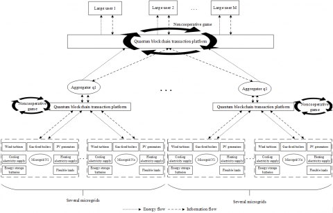
In the market of multiple microgrids, the players are mainly microgrids, large users, and aggregators. Each kind of players seeks to maximize their own benefits through active operation
In this paper, each microgrid mainly participate in the production and sale of electricity. When the system lacks electricity, the microgrid needs to purchase the shortage from aggregators. Each aggregator mainly collects and stores the scattered electricity from microgrids, and sells the natural gas purchased from the outside to microgrids, earning profits from the difference between purchase and selling prices. Each large user only purchases electricity, and does not engage in electricity production or sales.
5.1 Noncooperative game model
(1) Players
As shown in Figure 3, the game of the noncooperative game model for multi-microgrid transaction mostly takes place in period t between the aggregators and large users, who have the need of electricity sales/purchase, and between the microgrids and aggregators, who have the need of electricity sales/purchase.
(2) Strategy space
Suppose the strategy of every game player is to purchase electricity at the unit cost of $C_{b, t}$ and sell electricity at the price of $p_{s, t}$.
The cost of a microgrid to purchase electricity and natural gas in essentially the electricity selling price and natural gas price of aggregators in period t. Hence, the strategy space of the microgrid does not need to include the purchase costs of electricity and natural gas. To maximize its own profit, the microgrid needs to determine its scattered electricity selling price according to the specific situation of electricity supply and demand. Therefore, the game strategy of the microgrid for electricity sales can be defined as:
$\eta _{sell}^{W}=\{{{p}_{M-{{J}_{j}}}}\}$ (29)
The large user does not engage in electricity production or sales. Therefore, the game strategy space of the large user focuses on the cost of purchasing electricity at a low price. The strategy space of the large user can be defined as:
$\eta _{buy}^{Y}=\{{{p}_{_{Y-{{M}_{i}}}}}\}$ (30)
The aggregator mainly collects and stores the scattered electricity from microgrids, and earns profits from the difference between purchase and selling prices. The energy storage cost is excluded from the game space, because it is a constant term. The strategy space of the aggregator mainly concentrates on electricity selling price:
$\eta _{sell}^{J}=\{{{p}_{_{J-{{M}_{i}}}}},{{p}_{J-{{Y}_{k}}}}\}$ (31)
Figure 3. Basic framework of noncooperative game for multi-aggregator transactions
(3) Objective function
Through the competitive game, all three parties, namely, microgrids, large users, and aggregators, aim to maximize their own benefits, i.e., obtain the maximal profits at the lowest cost. The objective functions of each microgrid (32), each large user (33), and each aggregator (34) can be established based on formulas (17)-(20):
$\max W=\max (\sum\limits_{i=1}^{n}{{{C}_{_{Y-{{M}_{i}}}}}\cdot {{p}_{M-{{J}_{j}}}}})$ (32)
$\min {{C}_{Y}}(t)=\min (\sum\limits_{i=1}^{N}{{{C}_{_{Y-{{M}_{i}}}}}\cdot {{p}_{_{Y-{{M}_{i}}}}}})$ (33)
$\begin{align} & \max {{W}_{A}}(t)=\max (\sum\limits_{i=1}^{N}{{{p}_{_{J-{{M}_{i}}}}}\cdot {{Q}_{_{J-{{M}_{i}}}}}}+\sum\limits_{k=1}^{U}{{{p}_{J-{{Y}_{k}}}}\cdot {{Q}_{M-{{Y}_{k}}}}}) \\ & -\sum\limits_{i=1}^{N}{{{C}_{_{J-{{M}_{i}}}}}\cdot {{p}_{_{J-{{M}_{i}}}}}}-{{C}_{battery}}\cdot {{Q}_{battery}} \end{align}$ (34)
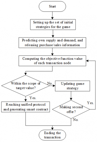
5.2 Flow of noncooperative game
Figure 4 explains the flow of competitive game between aggregators, multiple microgrids, and large users.
(a) Each game player sets its set of initial strategies for the competitive game. Node k generates $n_{a}$ different offers randomly in its scope of target value. The set of price strategies of node k in period t can be expressed as:
${{n}_{k}}(t)=\{{{p}_{k1}}(t),{{p}_{k2}}(t),...,{{p}_{k{{n}_{a}}}}(t)\}$ (35)
Figure 4. Flow of competitive game between nodes
(b) Each node releases purchase/sales information based on the predicted electricity supply and demand. Node k predicts its own electricity supply and demand in period t, releases purchase/sales information to the blockchain platform. Next, the node generates a transaction proof and an information transmission address, using the public key and private key, and then releases its purchase/sales information:
$I_{inB}^{k}=\{[Q_{sell}^{k}orp_{sell}^{k}]\text{ }\!\!|\!\!\text{ }[t,t+\Delta t],|{{k}_{publickry}}|T_{address}^{k}\}$ (36)
where, $k_{\text {publickry }} \mid T_{\text {address }}^{k}$ is the node address computed by node k with the public key.
(c) Each node updates its game strategy according to the information released in the platform. Referring to the information released in the platform and its own electricity demand, node h calculates the target value of node k, and judges whether the target value meets its own conditions. If not, node h will adjust its strategy, and demand node k to make another offer, or terminate the transaction.
(d) The objective function value is updated by the game strategy. If node h accepts the sales/purchase strategy of node k, the two parties will reach an agreement and generate a smart contract. The script of such a smart contract can be expressed as:
$C_{trk-h}^{i}=[{{S}_{signk}}|{{S}_{signh}}||{{Q}_{i}}|[t,t+\Delta t]|{{p}_{i}}]$ (37)
where, $S_{\text {signk }}$ is the script signed by node $\mathrm{k} ; S_{\text {signh }}$ is the script signed by node $\mathrm{h} ; Q_{i}$ is the agreed volume of electricity; $p_{i}$ is the agreed electricity price.
To verify the effectiveness of our noncooperative game model, this section sets up a noncooperative game system for regional multi-microgrid market. Four microgrids $M_{i}$, two aggregators $J_{j}$, and two large users $Y_{u}$ were selected as the players of the competitive game. Every player aims to maximize its own benefit through the game. For all players, the purchase price of electricity was substituted by the corresponding selling price. To reduce the dimensionality and complexity of model computing, it is assumed that the aggregators have a relatively fixed cost of collecting distributed energy in different periods, and that the microgrids purchase electricity at the expected selling price of electricity.
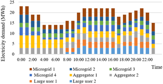
Figure 5. Predicted electricity demands of nodes in different periods
Firstly, the bidding strategy interval of microgrids was defined as 0.5-1.05 yuan/kWh, that of aggregators as 0.5-1.1 yuan/kWh, and that of large users as 0.5-1.05 yuan/kWh. Figure 5 shows the predicted electricity demands of nodes in different periods. Figure 6 presents the electricity selling abilities of aggregators and microgrids in different periods.
Figure 6. Electricity selling abilities of nodes in different periods
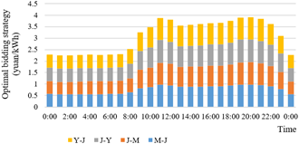
To improve the simulation efficiency, our simulation platform uses eight computers to mimic the game nodes. The bidding strategies of nodes in different periods were obtained through the simulation (Figure 7).
Figure 7. Bidding strategies of nodes in different periods
Taking 11:00 for example, each node achieved the strategy combination for the optimal electricity price through the noncooperative game:
$\begin{align} & {{p}_{M\to J}}=0.98yuan/(kW\cdot h) \\ & {{p}_{J\to M}}=0.94yuan/(kW\cdot h) \\ & {{p}_{J\to Y}}=1.00yuan/(kW\cdot h) \\ & {{p}_{Y\to J}}=0.95yuan/(kW\cdot h) \\\end{align}$
The above data show that the electricity demand in the period reached the daily peak in the morning. All nodes want to make more benefit by selling electricity at a higher price. The microgrids set the selling price of electricity to aggregators at 0.98 yuan/kWh. Therefore, the price offered by aggregators to the microgrids should not surpass 0.98 yuan/kWh in the optimal bidding strategy of the aggregators. Besides, the transaction will be difficult to complete, if the offer is too low. Therefore, the optimal bidding strategy of the aggregators must ensure that the price offered to microgrids falls in 0.93-0.98 yuan/kWh, and the price offered to the big users falls in 0.98-1.03 yuan/kWh. Figure 7 shows that the bidding strategies of microgrids, large users, and aggregators were all within the optimal ranges. Under these strategies, all players can achieve the best benefit, and realize Pareto optimization.
Through the above analysis, it is confirmed that our noncooperative game model drives the optimal bidding strategies, and maximizes the benefits of every node involved in electricity transaction. Thanks to our game model, microgrids and large users can purchase electricity at a moderate cost, and all nodes can make extra profits through transaction.
With the rapid development of distributed energy, the traditional energy system is transforming at an increasingly fast speed. The market transaction via energy Internet will be the inevitable trend of the electricity market. To improve the security of transaction platform, and guarantee the security and privacy of transaction and user information, this paper develops a multi-microgrid game model based on the quantum security of quantum blockchain, and constructs an NIZK-free two-round PAKE protocol, using MP-SPHF and Reg-SPHF. In addition, a quantum signature was created using two-particle entangled Bell states, aiming to authenticate node identity, ensure the truthfulness and reliability of user identity, and enhance the trust between nodes. After setting up a transaction platform with high quantum security, the noncooperative game model was introduced to promote nodes to make real price offers, realize the optimal bidding strategies, and maximize their own benefit. The proposed noncooperative game model was proved effective through case analysis. Our quantum blockchain-based multi-microgrid game model can meet the various requirements of electricity transaction, e.g., low platform management cost, high security, and timely consumption of scattered electricity, and guarantee the flexible transaction between microgrids, aggregators and large users. In addition, our model effectively reduces the electricity purchase cost, maximizes the interests of all players, and promotes the further transformation of energy transaction. However, the game model does not consider many types of tradable energies. In future research, more types of transactions, such as carbon quota and shared energy storage, will be taken into account.
This paper was supported by National Social Science Fund Project (Grant No.: 19BGL003).
[1] Ye, P., Qu, K., Sun, F., Zhang, M., Zhang, N. (2021). Research status and Prospect of integrated energy system collaborative control based on energy Internet. E3S Web of Conferences, 257: 1-4. https://doi.org/10.1051/e3sconf/202125702010
[2] Li, P., Tian, C., Zhang, Z., Li, M., Zheng, Y. (2021). Analysis of influencing factors of energy consumption in rural Henan based on symbolic regression method and Tapio model. Energy Sources, Part A: Recovery, Utilization, and Environmental Effects, 43(2): 160-171. https://doi.org/10.1080/15567036.2019.1623951
[3] Han, X., Yuan, Y., Wang, F.Y. (2019). Security problems on blockchain: The state of the art and future trends. Acta Automatica Sinica, 45(1): 206-225. https://dx.doi.org/10.16383/j.aas.c180710
[4] Zhang, N., Wang, Y., Kang, C.Q., Cheng, J.N., He, D.W. (2016). Blockchain technique in the energy internet: Preliminary research framework and typical applications. Proceedings of the CSEE, 36(15): 4011-4023. http://dx.chinadoi.cn/10.13334/j.0258-8013.pcsee.161311
[5] Li, Z., Kang, J., Yu, R., Ye, D., Deng, Q., Zhang, Y. (2017). Consortium blockchain for secure energy trading in industrial internet of things. IEEE Transactions on Industrial Informatics, 14(8): 3690-3700. https://doi.org/10.1109/TII.2017.2786307
[6] Thakur, S., Breslin, J.G. (2018). Peer to peer energy trade among microgrids using blockchain based distributed coalition formation method. Technology and Economics of Smart Grids and Sustainable Energy, 3(1): 1-17. https://doi.org/10.1007/s40866-018-0044-y
[7] Gong, G., Wang, H., Yang, S., Sun, Y., Su, C., Wen, Y., Yang, H. (2020). Integrated energy service based on blockchain technology. Proceedings of the CSEE, 40(5): 1397-1408. http://dx.chinadoi.cn/10.13334/j.0258-8013.pcsee.190062
[8] Shen, X., Chen, S., Yan, Z., Ping, J., Luo, B. (2021). Analysis on value, application scenarios and applicability of blockchain in energy industry. Automation of Electric Power Systems, 45(5): 18-29. http://dx.chinadoi.cn/10.7500/AEPS20200715003
[9] Danzi, P., Angjelichinoski, M., Stefanović, Č., Popovski, P. (2017). Distributed proportional-fairness control in microgrids via blockchain smart contracts. 2017 IEEE International Conference on Smart Grid Communications (SmartGridComm), Dresden, Germany, pp. 45-51. https://doi.org/10.1109/SmartGridComm.2017.8340713
[10] Luo, F., Dong, Z.Y., Liang, G., Murata, J., Xu, Z. (2018). A distributed electricity trading system in active distribution networks based on multi-agent coalition and blockchain. IEEE Transactions on Power Systems, 34(5): 4097-4108. https://doi.org/10.1109/TPWRS.2018.2876612
[11] Bouraga, S. (2021). A taxonomy of blockchain consensus protocols: A survey and classification framework. Expert Systems with Applications, 168: 114384. https://doi.org/10.1016/j.eswa.2020.114384
[12] Ante, L., Steinmetz, F., Fiedler, I. (2021). Blockchain and energy: A bibliometric analysis and review. Renewable and Sustainable Energy Reviews, 137: 110597. https://doi.org/10.1016/j.rser.2020.110597
[13] Sun, X., Wang, Q., Kulicki, P., Sopek, M. (2019). A simple voting protocol on quantum blockchain. International Journal of Theoretical Physics, 58(1): 275-281. https://doi.org/10.1007/s10773-018-3929-6
[14] Horoshko, D., Kilin, S. (2011). Quantum anonymous voting with anonymity check. Physics Letters A, 375(8): 1172-1175. https://doi.org/10.1016/j.physleta.2011.01.038
[15] Zhou, L., Wang, Q., Sun, X., Kulicki, P., Castiglione, A. (2018). Quantum technique for access control in cloud computing II: Encryption and key distribution. Journal of Network and Computer Applications, 103: 178-184. https://doi.org/10.1016/j.jnca.2017.11.012
[16] Cheng, S., Huang, T., Wai, R. (2019). Multi-time-scale Optimal Scheduling of CCHP Microgrid with Ice-storage Air-conditioning. Automation of Electric Power Systems, 43(5): 30-40.
[17] Li, Z., Wang, D. (2018). Two-round PAKE protocol over lattices without NIZK. International Conference on Information Security and Cryptology, Fuzhou, China, pp. 138-159. https://doi.org/10.1007/978-3-030-14234-6_8
[18] Shi, J., Xu, D., Xu, G., Lee, M.H. (2012). Quantum communication scheme for blind signature with two-particle entangled quantum-trits. 2012 14th International Conference on Advanced Communication Technology (ICACT), PyeongChang, Korea (South), pp. 558-561.