Khalid Faisal Sultan | Mohammed Hassan Jabal | Ameer Abed Jaddoa*
© 2021 IIETA. This article is published by IIETA and is licensed under the CC BY 4.0 license (http://creativecommons.org/licenses/by/4.0/).
OPEN ACCESS
The aim of this article was to examine the effect of hybrid nano – coating that could potentially impact the enhancement of heat transfer coefficient of distilled water, Reynolds number, and temperature through a swirl heat exchanger, as well as the indicator of the effect Zeta voltage in the coating process. In this experimental work, type of coating used was Aluminum (Al) + Aluminum oxide Al2O3. Outcomes of study showed that the coating of heat exchanger is much better than without coating in improving the thermal properties for liquids passing through heat exchanger as well as increasing the heat exchange through the surface of the exchanger. Results in the article indicated that the use of hybrid nano – structure coating is for inducing the feature of super – hydrophobicity for the surface that touches the fluid included within the heating transferring. Such feature can make an increase in the heating transferring factor and a decreasing in power losing produced via friction. This article indicated that the Zeta voltage analysis is to show the stability of the hybrid nanofluids used in the coating process. The enhanced technology depends upon the concept that exists in nature under the name “Lotus effect” to get super-hydrophobic surfaces. The rate of improvement in heat transfer using hybrid nanoparticles is 33% compared to that without coating condition.
hybrid nano-coating, heat exchangers, lotus effect, solar systems
Most of the surveys on the effects caused by slip flow have been based on flows in micro-channels and Nano - channels [1, 2] because in scales larger than the mill metric one, these effects are not visible. This paper discusses these effects on mill metric scales ducts coated by a special class of materials called super hydrophobic which are able to reduce wettability of fluids in contact to this kind of surfaces and so to switch the viscous friction behaviour from sliding to rolling. This is much evident as fluid contact angle increases. The effects on heat transfer are the increases of the heat transfer coefficient because of an induced temperature gradient grow to the wall. The super-hydrophobic coating is achieved by synthesizing via sol-gel a nanostructured ceramic layer and functionalizing it with fluoroalkysilane (FAS) able to induce such a low wettability that corresponds to about 150° contact angle. Drag decrease in tempestuous streams could be accomplished via various systems. Notwithstanding, in pressure-driven laminar streams, the utilization of excessively hydrophobic surfaces speaks to one of the first advancements fit for diminishing drag in quite a while that are 2 bigger than the atomic scale. The improvement of these surfaces (given their capacity to create critical drag decrease over a wide scope of Reynolds numbers, both laminar and tempestuous) could significantly influence an assortment of significant existing advancements [3].
Heating exchanger effectiveness represents one of the fundamental worries in attempting to enhance the general productivity of portable off – street machines and mechanical plants. Minimized radiators assume a basic job in temperature control of interior burning motors (ICE) and half and half drivelines. the enhancement for such segment can influence the worldwide productivity of the machine. Regularly, the issue may be contemplated from a geometrical perspective, utilizing distinctive creation lines to make balances geometries committed to improve the heating trade or to diminish the weight drop. Heating exchanger enhancements are expected to acquire littler, lighter, and yet increasingly proficient radiators [4]. In a steam build up application, the utilization of a hydrophobic covering enhanced the general heating factor of in excess of multiple times [5]. In cooling application, the weight dropping and the heating move were examined thinking about a hydrophilic covering and another relationship between heating, mass and energy move was proposed to depict the got outcomes [6]. Moreover, the utilization of a hydrophilic covering improved the heating move execution as well as diminished the weight dropping in a dehumidifying application [7]. The covering capacity to advance smooth movement after the use of outside powers had been considered in the laminar field of movement [8] and in violent conditions [9, 10]. A connection between slip length and contact point was contemplated in Ref. [11]. Wettability refers to the capacity of a fluid to keep in touch with a strong surface. The wettability of the surface affects heating trade, since it impacts the sort of movement that is built up among surface and liquid. The effect of wettability impact on heat move had been examined in Ref. [12]. The impact of contact edge or surface wettability) on the convective warmth move coefficient in small scale diverts was contemplated in the study [13], while a relationship between the contact edge and the wetting properties was proposed by Liu et al. [14]. In none of the past examinations, nonetheless, the conceivable association between the decrease of the erosion between the liquid and the surface, by methods for the nano organized covering and the expansion in the warmth trade performance had been explored.
Environmental worries about fossil fuel consumption are increasing as energy demands continue to expand rapidly. Many energy studies have sought to maximize the efficiency of various forms of renewable energy. Solar energy is the most widely used renewable energy source today [15]. Buildings can be heated and cooled using solar energy [16], Water desalination [17], home water heating [18], and a variety of industrial applications various advancements have made solar energy more effective to use [19] and store [20]. Solar collectors are devices that gather solar energy and reuse it for human consumption, either directly or indirectly. The core concepts of these solar devices have been known since the 1700 s. We've been able to develop more effective solar collectors thanks to our growing understanding of conduction, convection, radiation, photoelectric effect, and material sciences. Improvements in these technologies have reduced reliance on traditional fossil fuels as a source of energy. Solar collectors are wave absorption media that convert solar radiation into heat or electricity [21]. Solar photovoltaic (PV) collectors turn the sun's energy into electricity. Solar thermal collectors (STC) convert solar irradiation to heat, whereas solar photovoltaic thermal collectors (PTC) convert incident solar irradiation to heat and electricity. Modern designs, particularly in solar thermal collector technology, have increased the amount of energy consumed from the sun. The solar thermal collector is a heat exchanger in which a selected material collects solar radiation and transfers that energy to a working fluid (air, water, nanofluid, or oil) for use in other applications. Despite the fact that the thermal efficiency of these collectors has improved over time, the thermal efficiency of these collector systems must be improved further until they reach the highest possible system efficiency. Nanofluids have the potential to improve the thermal efficiency of these heat collection systems significantly. Eastman and Choi [22] published a study demonstrating that nanoparticle dispersions can improve the thermal conductivity of base fluids. Several researchers have attempted to use these nanofluids in a variety of heat transfer systems, with varying degrees of success [23-25].
In Ref. [26], nanostructured carbon Nanotube coating was shown to improve heat transfer. The heat flux is improved by using a CNT layer on the surface. The increase in convective heat transfer and area of contact is primarily responsible for the rise in heat flux; however, it was discovered from the review that CNT coating boosts heat transfer rate to some amount. The inertia – capillarity model was discussed by Jang and Song [27] to predict the minimal coating thickness in slot coating. It takes into account the inertia effects of the flow exiting the slot, unlike the visco capillary model. As a result, its prediction is more accurate than the visco capillary model for high coating speeds or large capillary numbers. They also compared the minimum coating thickness determined by the two models and simulations, finding that the inertia – capillary model predictions are in excellent agreement with the simulation results for all operating conditions, regardless of coating speed or fluid properties under consideration. This approach can be used to Reynolds numbers of at least 50, according to the researchers. The study [28] showed how to use a three – dimensional numerical model to calculate heat transport in a two-layer system with imperfect thermal contact and phase change. Cooling is highly dependent on the substrate's ability to absorb heat, as defined by its thermal diffusivity and conductivity the result demonstrates that when the heat conductivity is low, the influence of the substrate roughness is more noticeable. The presence of thermal gradients at the interface due to the random character of surface roughness is also ascribed to the splat fragmentation observed on non – heated substrates. As a result, the random contact distribution was incorporated into a multiphase model that included splat spreading and solidification. Rajput and Kulkarni [29] proposed that employing carbon Nanotubes for heat transfer enhancement will boost the heat transfer rate while lowering the weight with increasing air Reynolds number, the thermal performance of a radiator using Nanofluid or a blend of ethylene glycol + water (50 percent volume concentration) coolant improves. Based on the air side at a constant mass flow rate (0.08 Kg/s) and varied air Reynolds number, the overall heat transfer coefficients increased by almost 70%.
In this work the performance of the heat exchanger was investigated with and without hybrid nanoparticles coating which used in solar heating system. As well as the type of coating that was used Aluminum (Al) + Aluminum oxide Al2O3. The indicator of the effect Zeta voltage in the coating process.
The outer and inner surface of the coil heat exchanger is modified with a thin coating of Aluminum (Al) and Aluminum oxide Al2O3 hybrid nanoparticles by a wet chemical method for improved stability and heat transfer properties. The properties of the hybrid nanoparticles used in the coating process as show in the Table 1.
Table 1. Properties of the hybrid nanoparticles
|
Base fluid |
ρ (Kg/m3) |
Cp (J/kg k) |
k (W/m k) |
β *105 (k-1) |
α *105 (m2/s) |
|
Aluminum (Al) |
2707 |
896 |
236 |
2.4 |
973 |
|
Aluminum oxide Al2O3 |
3970 |
765 |
40 |
0.85 |
131.7 |
2.1 Zeta voltage analysis
Zeta represents a significant indicator of the interacting amid particles and minutes within a given solution. As these particles suspended in the solution acquires a surface charge, either as a result of the ionization of some of the surface chemical aggregates or because of the adsorption of charged particles of the solution. The fact that this charge is negative or positive varies according to the nature of the surface of the grave. This surface charge leads to the formation of a charged layer that surrounds the core within the center (the base fluid). When this is due to Brownian movement, such charged layer passages within the fluid as a part for mass. Therefore, the voltage difference between the original location of the object and the new location is called the zeta voltage and the level of motion is called the sliding level Slipping plane), see Figure 1.
The importance of such effort lies in its direct relationship with its fluid stability, in other words stabilizing the particles within the base fluid and not leaning towards the aggregation to form large aggregates deposited in the bottom and thus the fluid inefficiency. Therefore, the Zeta voltage represents the boundary between the stable or unstable solution [30] and the Zeta voltage standard values according to Table 2. The process of measuring the Zeta fluid flow was performed by a Zeta potential analyzer (Zeta Plus USAA).
Figure 1. Diagram of the principle of the zeta voltage [30]
Table 2. Zeta voltage standard values (ASTM) [31]
|
Zeta potential value (mV) |
stabilization conduct |
|
From 0 to ±5 |
Fast coagulating or flocculating |
|
From ±10 to ±30 |
Incipient stabilization |
|
From ±30 to ±40 |
Modest stabilization |
|
From ±40 to ±60 |
Good stabilization |
|
More than ±61 |
Outstanding stabilization |
Table 3. Zeta voltage and state for hybrid nanofluid used in coating
|
(Al+Al2O3) Hybrid nanofluid |
Hybrid nanoparticle size (Ps)(nm) |
|
|
The state |
Zeta potential (mV) |
|
|
Good stability |
- 47.35 |
50 |
The ZETA voltage analysis is to show the stability of the hybrid nanofluid used in the coating process. This is agreement with the study [31-36]. Table 3 indicates the zeta voltage analysis.
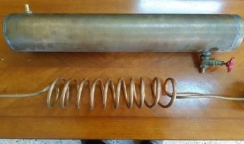
The experiment setup was divided to make two experiments. The experiment loop design had been made to convective heating transferring in laminar flow domain. The test section as shown in Figure 2 without hybrid nanoparticles coating. The heating exchanger was made of cupper and test area had the helically curled cylinder inner distance across of 13 mm, the outside measurement of 16 mm and shell inward breadth of 370 mm and outer width 385 mm and 1000 mm length testing segment. The set – up had helically snaked cylinder side circle and shell side circle. To gauge the wall temperature of the copper tube and the mass mean temperature of the liquids at the channel and out let of the cylinder two thermocouple (T – types) were embedded at the delta and out let of the test area. The weight dropping was estimated via dual measure pressures. To protect a consistent temperature at the bay of the test segment the warmed liquid comes back to repository tank passing winding copper heat exchanger to a cooler liquid. The stream meter had been situated soon after the pump discharge.
Figure 2. The user cooling system in solar heating systems without hybrid nanoparticles coating
The coating process involves several stages, namely:
1. Phase I provides for the removal of fats and oils using a basal solution where it is immersed in a hot basal solution at 50℃ for 5 minutes after which it is washed with water thoroughly.
2. Phase II Stimulation using a solution of diluted hydrochloric acid for 0.5 min and the solution is at room temperature and wash with water thoroughly.
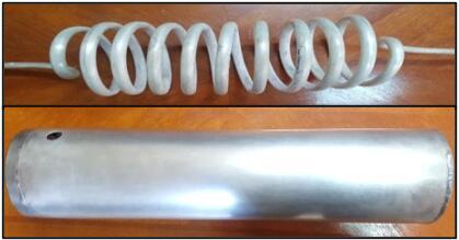
3. Phase III Stage paint including no electrician coating using Aluminum and Aluminum oxide. The piece to be painted is immersed in a previously prepared Aluminum and Aluminum oxide coating solution with stirring for the purpose of homogeneity of the paint for a period of 3 – 5 minutes and then washed well with water and then dried using hot air.
Figure 3. The user Cooling System in Solar Heating Systems with hybrid nanoparticles coating (Aluminum (Al)+ Aluminum oxide Al2O3)
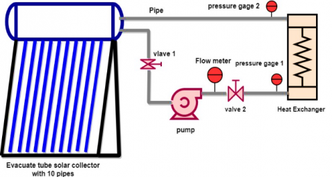
Figure 4. Flow diagram of the solar heating system
Figure 3 shows the test section with hybrid nanoparticles coating (Aluminum (Al) + Aluminum oxide Al2O3). Figure 4 indicated flow chart to the solar heating system used for experiments.
3.1 Data processing and validation
The heat transfer for water is estimate from Eq. (1). There was no consideration given to Fouling element.
$\mathrm{Q}_{\mathrm{Dw}}=\mathrm{m}_{\mathrm{Dw}} \mathrm{Cp}_{\mathrm{Dw}}\left(\mathrm{T}_{\text {in }}-\mathrm{T}_{\text {out }}\right)_{\mathrm{Dw}}$ (1)
The general heating transferring factor, Uo, was measured according to the temperature info and the heating transferring ratio by employing the subsequent [37]:
$\mathrm{U}_{\mathrm{O}}=\frac{\mathrm{Q}_{\mathrm{DW}}}{\mathrm{AoLMTD}}$ (2)
AS: Ao stands for the surface area; QDW refers to the heating transferring ratio; and LMTD represents the log mean temperature variance depending on the inlet temperature variance, ∆T1, along with the outlet temperature difference, ∆T2.
$\operatorname{LMTD}=\frac{\left(\Delta \mathrm{T}_{2}-{ \Delta\mathrm{T}}_{1}\right)}{\ln \left(\frac{\Delta \mathrm{T}_{2}}{\Delta \mathrm{T}_{1}}\right)}$ (3)
$\mathrm{Q}=\mathrm{h}_{\mathrm{i}} \mathrm{A}_{\mathrm{i}}\left(\mathrm{T}_{\mathrm{w}}-\mathrm{T}_{\mathrm{b}}\right)$ (4)
$\mathrm{Nu}_{\mathrm{i}}=\frac{\mathrm{h}_{\mathrm{i}} \mathrm{d}_{\mathrm{i}}}{\mathrm{k}_{\mathrm{nf}}}$ (5)
The inner heating transferring factor and overall heating transferring factor of coiled tube were measured based on Equations (2 and 4). The Nusselt number can be measured as per Eq. (5). It calculates the convective heating transferring in the helical tube. The general heating transferring factor may be connected to the internal and outer heating transferring factors via the coming equation [37]:
$\frac{1}{\mathrm{U}_{\mathrm{o}}}=\frac{\mathrm{A}_{\mathrm{o}}}{\mathrm{A}_{\mathrm{i}} \mathrm{h}_{\mathrm{i}}}+\frac{\mathrm{A}_o \ln \left(\frac{\mathrm{D}_{\mathrm{i}}}{\mathrm{d}}\right)}{2 \pi \mathrm{K} \mathrm{L}}+\frac{1}{\mathrm{~h}_{\mathrm{o}}}$ (6)
As: Di stands for the internal diameter of the shell; d represents the distance across of the internal spiral tube; K represents the thermic conductivity of the cupper wall; and L is the length of the heating exchanger. The Nusselt number in shell side can be controlled by the accompanying definition.
$\mathrm{Nu}_{o}=\frac{h_{o} D_{h}}{k_{\mathrm{nf}}}$ (7)
As: Dh refers to the hydraulically diameter of shell which can be measured by the subsequent:
$\mathrm{D}_{\mathrm{h}}=\frac{4\left(\mathrm{~V}_{\text {shell }}-\mathrm{V}_{\text {tube }}\right)}{\pi(\mathrm{D}+\mathrm{d})\left(\mathrm{L}_{\text {sheel }}+\mathrm{L}_{\text {tube }}\right)}$ (8)
Similar to the heat transfer coefficient, the friction element for laminar flowing within helical coiled tube can for range of Dean Number (De) of (11.6 < De < 2000) can be related by means of [38]:
$\frac{\mathrm{f}}{\mathrm{f}_{\mathrm{s}}}=\left[1-\left[1-\left(\frac{11.6}{\mathrm{De}}\right)^{0.45}\right]^{2.22}\right]^{-1}$ (9)
where: $\mathrm{De}=\operatorname{Re} \sqrt{\left(\frac{\mathrm{d}}{\mathrm{De}}\right)}$.
The friction factor for helical coiled tube, f, is determined as [33].
$\mathrm{f}_{\mathrm{e}}=\frac{7.0144}{\mathrm{Re}} \sqrt{\mathrm{De}}$ (10)
The pressure drop of nanofluid in coil tubes is evaluated as:
$\Delta \mathrm{p}=\mathrm{f} \frac{\mathrm{L}}{\mathrm{D}} \frac{\rho \mathrm{V}^{2}}{2}$ (11)
The four balls that employing for each experiment in current work was standardized and manufactured from (AISI E-52100) chrome steel alloy. Balls specifications are show in Table 2.
The accurateness as well as the dependability of the experiment system, the heating transferring factors is empirically calculated by utilizing pure water as the work fluid. A comparison is made between the results of the experimental pressure drop and heating transferring coefficient with the results of Shokouhm et al. [39], Salimpour [40], Seban and Metauchlin [38]. The flowing in spiral coiled heat exchangers is defined as follows:
Nui $=0.112 \mathrm{De}^{0.51} \gamma^{-0.37} \operatorname{Pr}^{0.72}$ (12)
Nuo $=5.48 \mathrm{Re}_{0}^{0.511} \gamma^{0.546} \mathrm{Pr}^{0.226}$ (13)
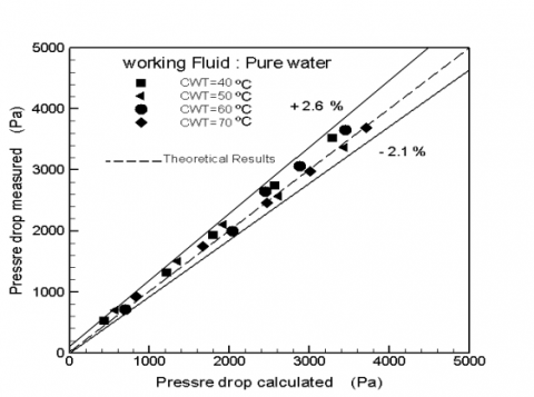
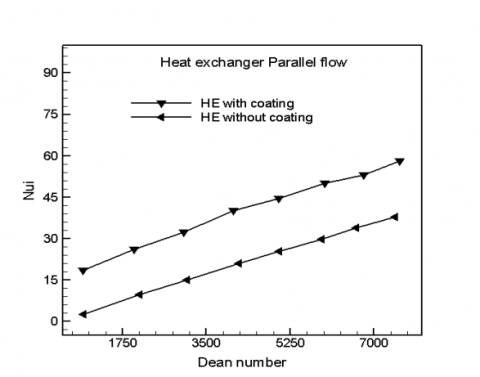
The change of experimental values with theoretical values for heat transfer coefficient as shown in Figure 5, therefor good agreement between these values in this figure. Figure 6 indicates the change of the hypothetical qualities for pressure dropping along the testing segment against the calculated pressure dropping. The trials are conducted at a similar condition clarified in the heating transferring approval. The deviation of the trial information from the hypothetical one is inside −2.1% plus + 2.6% as a shown in Figure 6. The changing of inner Nusselt number versus Dean Number for the flow of pure water as shown in Figures 7 and 8. By making a comparison between the counter and parallel flowing configuring, it is noticed that there is no important influence upon internal Nusselt number once circulating the pure water. Such behaviour can be attributed to whatsoever is the flowing configuring amid coiled tube and shell, the internal heating transferring factor will be no different. This indicates that the generating of secondary flowing as well as centrifugal force had not negative influence. Moreover, it is noticed that the internal Nusselt number increments with the effect the hybrid nanoparticles coating for inner wall and coil heat exchanger. This can be attributed to greater thermal conductivity and internal heating transferring factor. Generally, greater the convective heating transferring, greater the thermic conductivity will be. The coating with hybrid Nano fluid of aluminium and, aluminium oxide, led to an increase in Nusselt number for flow inside helical tube. In general, the coating of hybrid Nano fluids improves the thermic conductivity of the pure water. The improvement of thermic conductivity will increment the convective heating transferring factor. The coating of the hybrid nanofluids in flowing can interrupt the thermal boundary layer forming upon the tube wall surface. The developments of the thermic boundary layer are postponed.
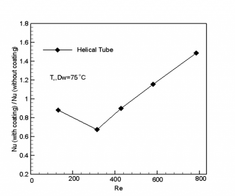
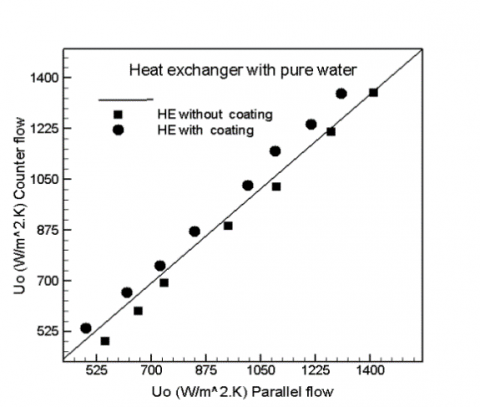
The ratios of Nusselt number of hybrid Nano fluids with coating to the one without coating as a role of Reynolds number for helical tube as explained inside Figure 9. The results indicated that around similar range of Reynolds numbers, the greatest Nusselt number rates can be got for the helical tube. The maxi increment of 25.18% with coating in Nusselt number rate for a Reynolds range numbers between 200 -800 get achieved for the coil tube. This case may be attributed to the coating of the hybrid nanoparticles in the coil wall tube. Because, the shear ratio close to the coil tube wall is high, the non – uniformity of the shear ratio through the cross section would increment and so, the coatings of hybrid nanoparticles are more active by the changing of the shear rate. Figure 10 indicated that the general heating transferring factor for counter flowing is 20-41% more than the one of parallel flowing with coating. The overall heat Transfer coefficient for counter flow was 4-11% more than that of parallel flow for without coating.
The changing in flowing direction has no effect on the general heating transferring, the cause behind that is the tube side primary flowing as well as generating the secondary flowing are at all times perpendicular to the shell side flowing. No important influence of heating transferring exists on altering the flowing condition. The outcomes for the parallel flowing configuring had been the same of the counter flowing. The ratios of heating transferring, though, are greatly higher in the counter flowing configuring, because of the increase log mean temperature variance.
Figure 5. Coefficient of heat transfer compared with calculated from [33, 35]
Figure 6. ΔP of theoretical and experimental to pure water
Figure 7. Changing of inner Nu number with & without coating HE in parallel flow
Figure 8. Changing of inner Nu number with & without coating HE in counter flow
Figure 9. Ratio of Nu number against Re number with & without coating HE in helical tube
Figure 10. Coefficient of overall heat transfer in counter & parallel flow arranging to with & without coating HE
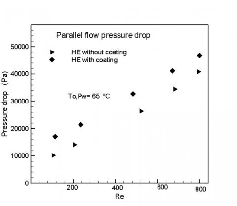
Figure 11. ΔP against Re number with & without coating HE in parallel flow
Figure 12. ΔP against Re number with & without coating HE in counter flow
The calculated pressure dropping of the flowing of distilled water as a task of Reynolds number alongside the coil tube can been seen in Figures 11 and 12, correspondingly. The outcomes pointed out an obvious increment in pressure dropping with coating of hybrid nanoparticles compared without coating. This is because of the fact that coating with hybrid nanoparticles generally increments dynamic viscosity compared with the movement of the pure water. Because, the viscosity can be in straight relation with pressure dropping, the greater value of pressure dropping creates increased quantity viscosity.
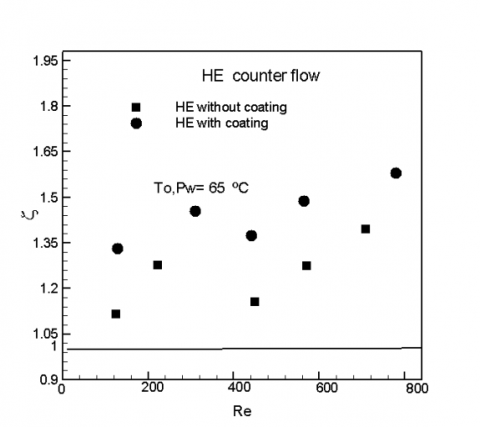
When applying the heat exchanger with coiled tube and shell with hybrid nanoparticles coating instead of the without coating, the convective heat transfer coefficient of enhanced. Therefore, these techniques for improvement of heat transfer with an increase in pressure drop can be used in an experimental implementation, to do this, the index of performance which considers a new parameter, ζ, can be defined as:
$\zeta=\frac{\left(\frac{\mathrm{Nu}_{\quad{\text {with coating }}}}{\mathrm{Nu}, \text { without coating }} \quad \quad\right)}{\left(\frac{\Delta \mathrm{P}_{\text {with coating }}}{\Delta \mathrm{P}_{\text {without coating }}} \quad \quad\right)}$ (14)
Clearly, once the performing index is more than 1, this entails that the heating transferring method is more in the favour of heating transferring improvement rather than in the favor of pressure dropping increase. Consequently, the heating transferring techniques with performing indexes more than 1 will be feasible selections in applied usages.
The performing index is greater than 1 just for with and without coating of hybrid nanoparticles as show in Figures 13 and 14. The performance index with coating is more than the performing index without coating. This entails that for distilled water flowing alongside the coil tube, the increase ratio in pressure dropping is less than the increase in heating transferring factor.
Figure 13. Index of performance against Re number with & without coating HE in parallel flow
Figure 14. Index of performance against Re number with & without coating HE in counter flow
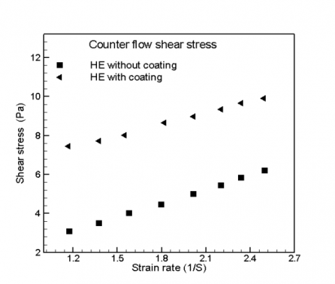
Figure 15. Shear stress against shear rate with & without coating HE in parallel flow
Figure 16. Shear stress against shear rate with & without coating HE in counter flow
The shear stress is plotted against shear rate as shown in Figures 15 and 16. The plot data for these types of with and without hybrid nanoparticles are not parallel, this indicates that the material is a Newtonian fluid over such range of shear stress. Therefor these figures indicated the shear stress increases with shear rate, for two cases and both flow counter and parallel flow. The shear stress and shear rate with coating are greater than the shear stress and shear rate without coating due to coating by hybrid nanoparticles. The ZETA voltage analysis is to show the stability of the hybrid nanofluid used in the coating process. This is agreement with the study [31].
The conclusions of this article as follows:
· The effect hybrid nanoparticles considered a significant part of the coating process and heat transfer rate enhancement from where type and synergistic.
· The changing of flow direction did not impact coefficient of overall heat transfer and the hybrid nanofluid (aluminium and aluminium oxide) behaves as the Newtonian fluid with and without coating heat exchanger.
· The performance index for heat exchanger with coating of the hybrid nano particles is greater than the performance index of the heat exchanger without coating.
· The pressure drop of heat exchanger with coating of the hybrid nanofluid is lower than the pressure drop of heat exchanger without coating for parallel flow and counter flow.
· The shear stress and shear rate with coating heat exchanger are greater than the shear stress and shear rate without coating heat exchanger due to coating by hybrid nanoparticles.
· The ZETA voltage analysis is to show the stability of the hybrid nanofluid used in the coating process. This is agreement with the study [27].
The authors are highly grateful to the University of Technology, Baghdad, Iraq for their support in completing this study.
|
D |
tube diameter, m |
|
Cp |
specific heat, J/kg k |
|
Nu |
Nusselt number |
|
d |
diameter of the coil, m |
|
Re |
Reynolds number |
|
Pr |
Prandtl number |
|
f |
friction factor |
|
∆P |
pressure drop, Pa |
|
De |
dean number |
|
fc |
friction factor of coil |
|
kn |
thermal conductivity of nanofluid, W/m2.K |
|
U0 |
general heating transferring factor, W/m2.K |
|
ASTM |
American Society for Testing and Materials |
|
Greek symbols |
|
|
γ |
shear rate, s-1 |
|
ζ |
performance Index |
|
Subscripts |
|
|
nf |
nanofluid |
|
hb |
hybrid |
[1] Rosengarten, G., Cooper-White, J., Metcalfe, G. (2006). Experimental and analytical study of the effect of contact angle on liquid convective heat transfer in micro channels. International Journal of Heat and Mass Transfer, 49(21-22): 4161-4170. https://doi.org/10.1016/j.ijheatmasstransfer.2006.02.057
[2] Yu, D., Choi, C., Kim, M.H. (2012). Pressure drop and dynamic contact angle in triple-line motion in a hydrophobic micro channel. Experimental Thermal and Fluid Science, 39: 60-70. https://doi.org/10.1016/j.expthermflusci.2012.01.009
[3] Rothstein, J.P. (2010). Slip on super hydrophobic surfaces. Annual Review of Fluid Mechanics, 42: 89-109. https://doi.org/10.1146/annurev-fluid-121108-145558
[4] Bonanno, A., Raimondo, M., Pinelli, M. (2019). Use of nanostructured coating to improve heat exchanger efficiency. In: Tolio T., Copani G., Terkaj W. (eds). Factories of the Future. Springer, Cham. https://doi.org/10.1007/978-3-319-94358-9_13
[5] Lara, J.R., Holtzapple, M.T. (2011). Experimental investigation of drop wise condensation on hydrophobic heat exchanger. Part II: Effect of coatings and surface geometry. Desalination, 280(1-3): 363-369. https://doi.org/10.1016/j.desal.2011.07.017
[6] Yu, Y.S., Wei, Q.D. (2006). Experimental study on physical mechanism of drag reduction of hydrophobic materials in laminar flow. Chin Phys Lett, 23(6):1634.
[7] Ma, X.K., Ding, G.L., Zhang, Y.M., Wang, K.J. (2009). Airside characteristics of heat, mass transfer and pressure drop for heat exchangers of tube-in hydrophilic coating wavy fin under dehumidifying conditions. Int J Heat Mass Transf., 52(19-20): 4358-4370. https://doi.org/10.1016/j.ijheatmasstransfer.2009.03.066
[8] Yu, J.G., Zhao, X.J., Zhao, Q.N., Wang, G. (2009). Preparation and characterization of super hydrophilic porous TiO2 coating films. Materials Chemistry and Physics, 68(1-3): 253-259. https://doi.org/10.1016/S0254-0584(00)00364-3
[9] Rothstein, J.P. (2010). Slip on super hydrophobic surfaces. Annual Review of Fluid Mechanics, 42: 89-109. https://doi.org/10.1146/annurev-fluid-121108-145558
[10] Martell, M.B., Rothstein, J.P., Perot, J.B. (2010). An analysis of super hydrophobic turbulent drag reduction mechanisms using direct numerical simulation. Phys Fluids, 22(6): 065102. https://doi.org/10.1063/1.3432514
[11] Bsushan, B., Wang, Y., Maali, A. (2009). Boundary slips study on hydrophilic, hydrophobic, and super hydrophobic surfaces with dynamic atomic force microscopy. Langmuir, 25(14): 8121-8117. https://doi.org/10.1021/la900612s
[12] Choi, C., Moohwan, K. (2011). Wettability effects on heat transfer. Two Phase Flow, Phase Change and Numerical Modeling, Dr. Amimul Ahsan (Ed.), InTech. https://doi.org/10.5772/19512
[13] Rosengarten, G., Cooper-White, J., Metcalfe, G. (2010). Experimental and analytical study of the effect of contact angle on liquid convective heat transfer in microchannels. Int J Heat Mass Transf., 49(21-22): 4161-4170. https://doi.org/10.1016/j.ijheatmasstransfer.2006.02.057
[14] Liu, K.S., Yao, X., Jiang, L. (2010). Recent development in bio – inspired special wettability. Chem Soc Rev., 39(8): 3240-3255. https://doi.org/10.1039/b917112f
[15] Dupont, E., Koppelaar, R., Jeanmart, H. (2020). Global available solar energy under physical and energy return on investment constraints. Applied Energy, 257: 113968. https://doi.org/10.1016/j.apenergy.2019.113968
[16] Hoseinzadeh, S., Azadi, R. (2017). Simulation and optimization of a solar-assisted heating and cooling system for a house in Northern of Iran. Journal of Renewable and Sustainable Energy, 9: 045101. https://doi.org/10.1063/1.5000288
[17] Bamisile, O.O., Babatunde, A.A., Dagbasi, M., Wole-Osho, I. (2017). Assessment of solar water heating in Cyprus: utility, development and policy. International Journal of Renewable Energy Research-IJRER, 7(3): 448-1453.
[18] Hoseinzadeh, S., Ghasemiasl, R., Javadi, M.A., Heyns, P.S. (2020). Performance evaluation and economic assessment of a gas power plant with solar and desalination integrated systems. Desalination and Water Treatment, 174(2020): 11-25. https://doi.org/10.5004/dwt.2020.24850
[19] Hoseinzadeh, S., Hadi Zakeri, M., Shirkhani, A., Chamkha, A.J. (2019). Analysis of energy consumption improvements of a zero-energy building in a humid mountainous area. J. Renew. Sustain. Energy, 11(1): 015103. https://doi.org/10.1063/1.5046512
[20] Ghasemiasl, R., Hoseinzadeh, S., Javadi, M.A. (2018). Numerical analysis of energy storage systems using two phase-change materials with nanoparticles. J. Thermophys. Heat Transf., 32(2): 440-448. https://doi.org/10.2514/1.T5252
[21] Kalogirou, S. (2009). Solar Energy Engineering. Academic Press. https://doi.org/10.1016/B978-0-12-374501-9.X0001-5
[22] Choi, S.U.S., Eastman, J.A. (1995). Enhancing thermal conductivity of fluids with nanoparticles. 1995 International Mechanical Engineering Congress aAnd Exhibition, San Francisco, CA (United States), pp. 99-105.
[23] Xian, H.W., Sidik, N.A.C., Najafi, G. (2019), Recent state of nanofluid in automobile cooling systems. J. Therm. Anal. Calorim., 135: 981-1008. https://doi.org/10.1007/s10973-018-7477-3
[24] Sajid, M.U., Ali, H.M. (2019). Recent advances in application of nanofluids in heat transfer devices: A critical review. Renew. Sustain. Energy Rev., 103: 556-592. https://doi.org/10.1016/j.rser.2018.12.057
[25] Thomas, S., Panicker Sobhan, C.B. (2011). A review of experimental investigations on thermal phenomena in nanofuids. Nanoscale Res. Lett., 6(1): 377. https://doi.org/10.1186/1556-276X-6-377
[26] Kumar, C.S.S., Suresh, S., Rajiv, K. (2012). Heat transfer enhancement by nanostructured carbon nanotube coating. International Journal of Scientific & Research, 3(6).
[27] Jang, I., Song, S. (2013). A model for prediction of minimum coating thickness in high-speed slot coating. International Journal of Heat and Fluid Flow, 40: 180-185. https://doi.org/10.1016/j.ijheatfluidflow.2013.01.002
[28] Amara, M., Timchenko, V., Ganaoui, M.E., Leonardi, E., de Vahl Davis, G. (2009). A 3D computational model of heat transfer coupled to phase change in multilayer material with random thermal contact resistance. International Journal of Thermal Sciences, 48(2): 421-427. https://doi.org/10.1016/j.ijthermalsci.2008.03.008
[29] Rajput, K.A., Kulkarni, A.V. (2014). A review on effect of perforation and carbon nanotubes coating on heat transfer augmentation. International Journal of Innovative Research in Science, Engineering and Technology, 3(2): 9412-9415.
[30] Leary, J.F. (2011). The Importance of Zeta Potential for Druge/Gene Delivery in Nanomadicine. Malvern Instrument Work shop, Purdue University (USA).
[31] Hunter, R.J. (1981). Zeta Potential in Colloid Science Principles and Applications. London: Academic Press.
[32] Khoshnevisan, K., Barkhi, M. (2015). Information about Zeta Potential. Institute of Agricultural Biotechnology, Nano Department, Karaj, Tehran, Iran. https://doi.org/10.13140/RG.2.1.4554.3844
[33] Derjaguin, B.V., Landau, L. (1941). Acta Physiochimist URSS. 14, 633.
[34] Verway, E.J.W., Overbeek, J.T.G. (1948). Theory of the stability of lyophobic colloids. Elsevier, Amsterdam.
[35] Hunter, R.J. (1988). Zeta Potential in Colloid Science: Principles and Applications. Academic Press, UK.
[36] Simplifying the Measurement of Zeta Potential Using M3 – PALS. Technical Note available from www.malvern.co.uk.
[37] White, F.M. (1984). Heat Transfer. Addison–Wesley Publishing Company Inc., New York.
[38] Seban, R.A., Mclauchlin, E.F. (1962). Heat transfer in tube coils with laminar and turbulent flow. International Journal of Heat and Mass Transfer, 6(5): 387-395. https://doi.org/10.1016/0017-9310(63)90100-5
[39] Shokouhm, H., Salimpour, M.R., Akhavan-Behabadi, M.A. (2008). Experimental investigation of shell and coiled tube heat exchangers using Wilson plots. International Communications in Heat and Mass Transfer, 35(1): 84-92. https://doi.org/10.1016/j.icheatmasstransfer.2007.06.001
[40] Salimpour, M.R. (2008). Heat transfer characteristics of a temperature-dependent property fluid in shell and coiled tube heat exchangers. International Communications in Heat and Mass Transfer, 35(9): 1190-1195. https://doi.org/10.1016/j.icheatmasstransfer.2008.07.002