Konstantin Osintsev | Sergey Aliukov | Sulpan Kuskarbekova*
© 2021 IIETA. This article is published by IIETA and is licensed under the CC BY 4.0 license (http://creativecommons.org/licenses/by/4.0/).
OPEN ACCESS
Stationary and mobile steam generators are widely used in low ambient temperatures, for example in areas described by the Köppen world map as subarctic. Such equipment is often used in oil and gas fields. At the moment, the existing standard boiler plants are outdated. The purpose of this work is an experimental study of a coiled-type direct-flow steam generator developed by the authors in the winter period at low ambient temperatures. The tasks to be solved to achieve the goal are associated with obtaining experimental data at different operating modes of the installation, their processing and the development of empirical coefficients of gas movement inside the coaxial cylinders of the steam generator. In addition, another task is to develop a theoretical basis for the obtained experimental data. Based on the results of the work, the dependences of pressure and temperature on fuel consumption in various modes were obtained. Statistical analysis was applied to the data obtained. The authors have developed equations for calculating the convective part in the process of radiant-convective heat transfer in coaxial gas ducts, taking into account the design features of a once-through coil-type steam generator. Finally, promising directions for further improving the efficiency of steam generators of this type are proposed.
boiler plant, coaxial cylinders, coils, convection, heat exchange
1.1 Possibilities of operation of the steam generator in low ambient temperatures
Transportable boiler plants (hereinafter referred to as TPB) are widespread in the northern regions of the Siberia described by the Köppen world map [1] as subarctic and are in demand in various spheres of life: servicing private houses in cities and small remote settlements, in industry, and in oil production.
At drilling sites that specialize in oil production, steam and hot water are required for the technological and individual needs of the maintenance personnel.
Oil fields in Russia are often equipped with block-modular boiler houses (hereinafter referred to as BMB) installations based on E-1.0-0.9 M(Z) boilers, which run on liquid fuel. Fuel consumption at nominal mode is 0.28 kg/s. The working pressure of the coolant on the manifold averages 0.4-0.45 MPa at a temperature of 143°C (416K).
In such boiler plants, there is a certain amount of necessary auxiliary equipment (chemical water treatment system, feed pumps, fans), which requires repair, replacement, and modification. The chemical water treatment system of such plants (hereinafter referred to as the CWT) does not cope with hard polluted water, putting it at risk and increasing the likelihood of boiler failure due to pipe fouling and burnout.
Our experimental and theoretical work involves the modernization of TPB (hereinafter referred to as MTPB), and in particular the complete replacement of boilers. When studying the options for a new boiler house available on the world market, we noted a number of manufacturers of heating equipment operating on liquid fuel whose products meet the requirements of the customer.
The above companies offer compact steel units with full automatic control, making it possible to operate units on different combined types of fuel thanks to the use of modern burners [2, 3]. The boilers are designed for domestic and industrial use and meet emissions standards.
1.2 Review of works on the research topic
Modern research in the field of steam generators is carried out by scientific laboratories and individual scientists from different countries around the world. Hernández Corona et al. [4] investigated the key points of the operation of the steam generator according to the criteria of its efficiency. Guidez and Prele [5] describe steam generators interesting from the point of view of design, which are similar in many factors to those considered in the article. Sharma et al. [6] investigated the principle of operation of heat utilizers based on standard boilers. Astorga-Zaragoza et al. [7] touched upon the facts of using steam generators at centralized heat supply facilities. Silva et al. [8] conducted mathematical modeling similar in purpose of the study to that considered by the authors of Deghal Cheridi et al. [9]. The authors note scientific developments on topics similar to the one under consideration. Moghari et al. [10] considered the modeling of water and steam in a steam generator, and Sunil et al. [11] studied new modeling techniques and their reliability for the movement of water and steam in the boiler drum. In studies by Hag et al. [12] paid attention to evaporation processes for a steam generator, and the article by Backi [13] considered a similar model. Despite the significant competition, domestic boilers are in great demand, both among large enterprises and among small consumers for a number of reasons.
Coil-type steam boilers, which are included in the MTPB project, are offered to the domestic market of the Ural region by UNISTEAM. The automation and intuitive control system of steam generators allows full control of the steam production process and tracking of costs through mobile devices (iOS and Android), through the Internet browsers Safari, Google Chrome, and Internet Explorer, and can be equipped with augmented reality elements.
In connection with the listed advantages and further development prospects of the domestic market for the production of water-tube coil and fire-tube boilers, we chose a coil-type steam boiler produced in the Urals. The characteristics of the boilers developed by the authors were compared with the analogues presented by Chauhan and Khanam [14], dedicated to mini thermal power plant with low-pressure steam generators, in which a boiler of a similar type operating on solid fuel is considered [15].
1.3 Coil-type once-through steam generator design
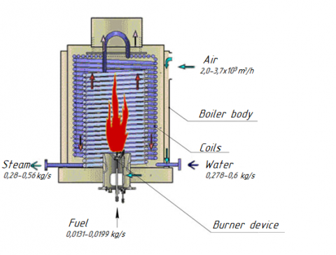
An upgraded transportable boiler plant was designed for the experiment. The main equipment is coil-type steam boilers (Figure 1).
Figure 1. Coil-type steam boiler
The installation consists of all the necessary main and auxiliary heating and electrical equipment. The MTPB is housed in a modular marine type container and is designed to operate in cold climatic conditions.
Our experiment involves the collection and analysis of the performance parameters of a coil-type steam boiler in the real operating conditions of the Far North. The installation to be studied is located at the cluster site of the Var-Yogan field in the winter heating season.
1.4 Goals and objectives of ongoing research
The purpose of this work is an experimental study of a once-through coil-type steam generator in winter at low ambient temperatures based on the methodology developed by the authors. We set a number of tasks to achieve our research goals: supply steam to the drilling rig and auxiliary units for heating equipment and the technological process of collecting basic data on the operation of a steam boiler; development of empirical coefficients of gas movement inside the coaxial cylinders of the steam generator; development of a theoretical basis for the obtained experimental data; construction and analysis of dependences of temperature and steam pressure on fuel consumption, on qualitative and quantitative parameters of feed water to justify economic and technical costs, advantages, and further prospects in the research and design of boiler houses.
Our novel boiler plant proposal, which includes coil-type steam boilers, is characterized by an increased heat transfer coefficient in the convective part, consisting of two coaxial cylinders (Figure 1), which makes it possible to turbulize the flue gas flow.
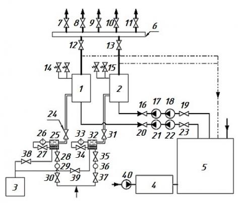
Measurements of temperature, pressure and velocity in the diagram in Figure 2 were carried out according to the methods approved in the Eurasian Economic Union.
Note: (1, 2) steam boiler; (3) reserve fuel tank; (4) chemical water treatment unit; (5) nutritional container; (6) distribution manifold; (7-9) valve (steam to the consumer); (10) valve (steam for own needs); (11) valve (steam for heating the tank); (12, 13) valve; (14, 15) relief safety valve; (16, 20) check valve; (17, 18, 21, 22) feed pump; (19, 23, 24, 27, 28, 30, 31, 34, 35, 37-39) valve; (25, 32) separator; (26, 33) fine filter; (29, 36) coarse filter; (40) pump
Figure 2. Schematic of the MTPB
However, the authors also focused on the recommendations of the European Union in the field of measurement uncertainty and the applied methodology. Measuring devices that were installed in the experimental boiler house according to scheme 2: pressure gauges showing on-site and electrical contact, Karat-520 water flow meter, Petroll fuel meter, thermocouples for measuring the temperature of steam and gases in different parts of the coils, Testo-320 gas analyzer for analyzing the composition of smoke gases. With the help of the above instruments, measurements were made of the main parameters (which are presented in Tables 3-5) for steam (pressure and temperature), water and fuel consumption, as well as the main indicators for flue gases (temperature, O2).
The development of a methodology for conducting experimental research is based on assessing the uncertainty arising from each of its sources. For example, the circuit in Figure 2 shows instruments for measuring flow, temperature and pressure. To determine the total uncertainty, it is necessary to determine each separately, and then use the formulas for the constructed model.
In the case of the authors' studies, the method itself contributes to the uncertainty; therefore, we express this contribution as a quantity that affects the final result. In this case, the parameter uncertainty is expressed directly in units of y, and the sensitivity coefficient ∂y / ∂x = 1.
The result of measurements of the vapor velocity - the arithmetic mean of 4.147 m / s is characterized by a standard deviation of 0.04 m / s. The standard uncertainty u (y) associated with precision under these conditions is 0.04 m / s. The model of this measurement in this case can be expressed by the formula y = (calculated result) + ε, where ε reflects all random effects in the given measurement conditions, and the sensitivity coefficient ∂y / ∂x = 1.
And finally, the resulting expanded uncertainty is 3.542%. According to the Guidelines for measurements and their uncertainties in the countries of the Eurasian Economic Union, a maximum value of 5% is adopted for experimental data, so the results obtained fall into the confidence interval.
The uncertainty of other quantities, such as temperature and pressure, was estimated in a similar way.
The determined uncertainty value is subject to revision only in the process of re-validation of the analytical procedure. The validation of the measurement methodology was carried out during repeated tests of the boiler unit in the conditions of work in the oil and gas industry in the Far North. The method is validated to ensure that the performance metrics obtained from the development of a method are achieved in a particular application. In the case of the author's studies, the methodology underwent an interlaboratory study, as a result of which additional data on efficiency were obtained.
Experiments were carried out on direct-flow coil-type boilers to measure the length of the torch, in particular, its initial section, as well as the height of the intense combustion zone. During the experiments, the methods approved for operation and measurement of parameters in high-temperature installations were used, for example, errors of primary and secondary measuring devices were multiplied. The discrepancy between the results of theoretical and experimental studies on measuring the temperature and length of the torch tended to 3%, which could be explained by some error when conducting experiments at high temperatures in boiler installations, for example, re-emission and high dust content of the torch in the furnace space. Our novel boiler plant proposal, which includes coil-type steam boilers, is characterized by an increased heat transfer coefficient in the convective part, consisting of two coaxial cylinders (Figure 3), which makes it possible to turbulize the flue gas flow.
This also intensifies heat transfer in an annular channel with a variable cross section, reducing the temperature of the gases at the outlet. A distinctive feature of the boiler unit is the ratio of the geometric dimensions of the boiler—the height of the furnace НF, the diameters of the coaxial cylinders of the coils D1 and D2, which are defined as HF=(2,00…2,10)·D1, HF=(1,70…1,90)·D2, moreover, similar characteristics are presented by Kuznetsov [16] for industrial medium pressure boilers and for low pressure boilers [17]. For the experimental sample, coils with radii (in the center of the coils) were used: for gas ducts - 602 mm and 774 mm, for an air heater (in the boiler casing) - 966 mm.
The intensification of heat transfer in the boiler is achieved by using coils of different diameters. Flue gases move along an annular channel with a variable cross section. With this arrangement, the total heat exchange surface is increased. The first coil has a larger diameter, which allows the coolant to obtain more heat and accelerate the vaporization process due to the amount of heat received and the narrowing of the flow area. An additional area of heat exchange is provided by a spiral coil installed on the ceiling of the boiler.
Figure 3. Coaxial cylinders consisting of spiral coils
Flue gas velocity was measured in laboratory conditions using an experimental stand. The aerodynamic characteristics of the fan were controlled by a frequency drive of the electric motor. The experiment was carried out with different diameters of the flue gas duct formed by the coils. The flue gas velocity is calculated from the pressure difference measured at the inlet and outlet of the flue gas duct. Based on the results of the experiment, we chose the optimal ratio between the aerodynamic drag of the gas-air duct and the maximum value of the flue gas velocity. The increased flue gas velocity and increased heat transfer area increased the convection heat transfer coefficient, increasing the heat transfer coefficient (1).
$k=\Psi \cdot\left(\alpha_{c}+\alpha_{r}\right)$ (1)
where, Ψ is the beam thermal efficiency coefficient; $\alpha_{c}$ and $\alpha_{r}$ are the heat transfer coefficients by convection and radiation in the convective part, respectively.
The average logarithmic temperature head of the built-in air heater increases due to the difference between cold (Tc.a) and hot air (Th.a.). In addition, the temperature difference $\Delta T=T_{\text {h.a. }}-T_{c . a}$ is increased due to the upper supply of the air flow movement when using the fan compared to the lower supply, without additional power consumption for the fan drive. With an increase in ΔТ by 120%, the air flow rate in the fan-boiler section increases by 122%. Under the same conditions, electricity costs increase by 0.80-0.90%.
The developed MTPB is used at oil drilling sites in the Far North, providing steam for the heating and technological needs of the drilling site derrick-winch and pumping units as well as a block of additional tanks.
The MTPB is designed on the basis of modern coil-type steam boilers and replaces steam boilers E-1.0-0.9 M(Z)-E. Due to the intensification of the heat exchange process, metal consumption has been reduced, which accordingly affected the overall dimensions of the boiler. The compact design allows the boilers to be installed in an upright position. The new boiler takes up less space in the boiler plant than one "E" boiler, which allows for automatic control cabinets to be installed side by side. The boilers are installed on metal supports, which made it possible to place the auxiliary equipment (burner device, heating elements, piping system) under the boiler unit.
During operational testing, the MTPB was operated in two modes to compare the results. A schematic diagram of the MTPB is shown in Figure 2. The first mode represents the operation of one boiler (in Figure 2, Symbols 1 and 2) and feed pumps (in Figure 3: 21, 22 and 17,18) in turn.
Mode 1. Experimental values of boiler operation 1 and 2, feed pumps 17, 18 and 21, 22, respectively, are shown in Tables 1, 2 and Figures 3-6.
Table 1. Experimental values of Steam boiler 1
|
No. |
No. |
G |
TW |
B |
TS |
ps |
|
[-] |
[-] |
[kg/s] |
[°C] |
[kg/s] |
[°C] |
[MPa] |
|
1 |
1 |
0.3094 |
44 |
0.0153 |
151 |
0.36 |
|
2 |
0.3317 |
44 |
0.0152 |
151 |
0.36 |
|
|
3 |
0.3336 |
44 |
0.0143 |
149 |
0.35 |
|
|
4 |
0.3492 |
46 |
0.0156 |
151 |
0.36 |
The correlation coefficient showing the relationship between the steam temperature and the fuel consumption for steam boiler No. 1 (Figure 4) is 0.948, which indicates a strong relationship between these values. A positive correlation close to unity allows us to assert that an increase in one value affects the growth of the second.
The correlation coefficient showing the relationship between the steam pressure and the fuel consumption of boiler No. 1 (Figure 5) is also 0.948. A similar conclusion about the relationship between the steam temperature and the fuel consumption was taken to be valid for these values.
The correlation coefficient showing the relationship between the steam temperature and the fuel consumption for steam boiler No. 2 is 0.89, which indicates a sufficient relationship of these values. A positive correlation indicates that an increase in one value contributes to an increase in another (Figure 6).
Figure 4. Relationship between steam temperature and fuel consumption in Steam boiler 1
Figure 5. Relationship between steam pressure and fuel consumption in Steam boiler 1
Table 2. Experimental values of Steam boiler 2
|
No. |
No. |
G |
TW |
B |
TS |
ps |
|
[-] |
[-] |
[kg/s] |
[°C] |
[kg/s] |
[°C] |
[MPa] |
|
2 |
1 |
0.3744 |
31 |
0.0187 |
159 |
0.49 |
|
2 |
0.4239 |
26 |
0.0190 |
160 |
0.50 |
|
|
3 |
0.4317 |
32 |
0.0187 |
159 |
0.49 |
|
|
4 |
0.4575 |
32 |
0.0188 |
159 |
0.49 |
The correlation coefficient showing the relationship between steam pressure and fuel consumption of boiler 2 is also 0.89. The above conclusion for the considered relationship between steam temperature and fuel consumption is also accepted for these parameters (Figure 7).
Figure 6. Relationship between steam temperature and fuel consumption in Steam boiler 2
Figure 7. Relationship between steam pressure and fuel consumption in Steam boiler 2
Mode 2. Simultaneous operation of two boilers with the inclusion of two feed pumps.
Both boilers and feed pumps are switched on to increase the steam output. All systems were working at full power. Table 3 shows the results of the experiment.
Table 3. Experimental values of two steam boilers in mode 2
|
No. |
No. |
G |
TW |
B |
TS |
ps |
|
[-] |
[-] |
[kg/s] |
[°C] |
[kg/s] |
[°C] |
[MPa] |
|
1 |
1 |
0.3428 |
45 |
0.0146 |
148 |
0.33 |
|
2 |
0.3403 |
45 |
0.0145 |
156 |
0.43 |
|
|
3 |
0.4019 |
53 |
0.0146 |
161 |
0.51 |
|
|
4 |
0.3517 |
55 |
0.0149 |
160 |
0.49 |
|
|
2 |
1 |
0.3808 |
45 |
0.0198 |
152 |
0.36 |
|
2 |
0.3717 |
45 |
0.0198 |
156 |
0.43 |
|
|
3 |
0.3342 |
53 |
0.0199 |
160 |
0.49 |
|
|
4 |
0.3561 |
55 |
0.0199 |
161 |
0.52 |
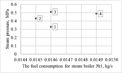
Figures 8 and 9 show the relationship between temperature, steam pressure, and fuel consumption in the first boiler, respectively.
The correlation coefficient showing the relationship between steam temperature and fuel consumption, as well as the relationship between steam pressure and fuel consumption for steam boiler 1 in the second mode is 0.2306 and 0.2352, respectively.
Figure 8. Relationship between steam temperature and fuel consumption in Steam boiler 1
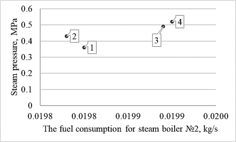
Figure 9. Relationship between steam pressure and fuel consumption in Steam boiler 1
Points 1 and 3 illustrate that with a large difference in vapor pressure, the fuel consumption changed by a small value ΔB = 0.00006 kg/s. A small drop in fuel consumption is associated with a sharp increase in the temperature of the feed water, Δt=8℃ (2). The increase in the temperature of the feed water reduced the boiler's need for higher fuel consumption to maintain steam parameters (2).
$B=\frac{D \cdot\left(h^{\prime \prime}-h_{f w}\right)}{N C V \cdot \eta} \cdot 100$ (2)
where, B is fuel consumption, kg/s; D is steam capacity, kg/s; $h^{\prime \prime}, h_{f w}$ is the enthalpy of steam and feed water, MJ/kg; NCV is net calorific value of fuel, MJ; η is boiler efficiency, %.
The experimental data also show that the feed water consumption at point 3 increased, which resulted in a sharp jump in all steam parameters at the boiler outlet. In connection with the analyzed corrections for the experimental values of temperature and feed water consumption, the smaller relationship between steam parameters and fuel consumption is explained.
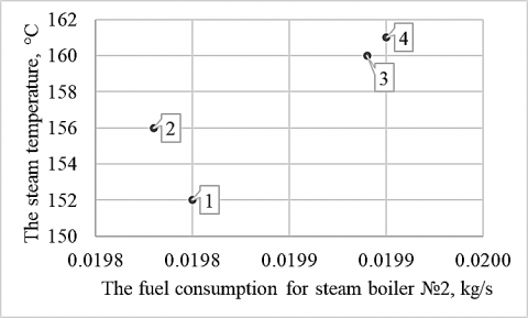
Figures 10 and 11 show the relationship between temperature, steam pressure, and fuel consumption at the first boiler, respectively.
The correlation coefficient calculated to study the relationship between temperature, steam pressure, and fuel consumption on boiler 2 was 0.6895 and 0.6888, respectively. The experiment on the second boiler was carried out with a gradual increase in all parameters of the coolant; therefore, a stronger relationship is traced between temperature, steam pressure, and fuel consumption.
Figure 10. Relationship between steam temperature and fuel consumption in Steam boiler 2
Figure 11. Relationship between steam pressure and fuel consumption in Steam boiler 2
Thus, the analysis of the dependences of steam parameters and fuel consumption showed that the low storage capacity of once-through boilers is reflected in the temperature and pressure of the steam with changes in fuel consumption. Depending on the operating factors, the heating surface of the superheating zone changes. To maintain constant parameters of the coolant, it is necessary to maintain the ratio of the flow rate of feed water and fuel.
Fuel consumption value is a dynamic characteristic for a once-through boiler. In a direct-flow boiler, the water-fuel ratio is regulated through the temperature and amount of feed water, by returning condensate, and installing a control valve. The change in this characteristic can be reflected by the fuel consumption formula (2). With low storage capacity, changes in the flow rate, quantity, and temperature of feed water affect the values $D$ and $h_{f w}^{\prime}$, which affects the instantaneous change in the fuel consumption value B.
Mode 3 (Table 3) for the first boiler and Mode 4 for the second are recorded in the performance-adjustment chart. In this mode, the outlet coolant is supplied with maximum parameters in terms of temperature and pressure at optimal fuel consumption for each boiler.
The coil-type boiler model has no drum. The vaporization process ends in a separator, which is installed outside the boiler. This has a positive effect on the quality of pipes during operation, deposits in the boiler elements form more slowly over time, thereby increasing the service life and reducing economic costs.
In their early works, the authors of the article presented the results of research on the operation of boiler units and heat and power equipment. For example, Toropov et al. [18] presented new methods for studying the operation of boiler units, and Toropov et al. [19] showed the possibility of organizing new methods in a new methodological framework. In addition, Alabugin et al. [20], propose to use the results of [19] for low-and medium-pressure thermal power equipment. It should be noted that the paper by Osintsev et al. [21] shows the possibility of using the results of the work [19] in order to organize neural network control of combustion processes, including natural gas combustion. Thus, the methodological basis of the article was laid by the authors earlier in the work [19]. When introducing a new boiler unit to the drilling site, the operating company studied the thermal diagram of the entire production and the indicators of the coolant in each block. This examination confirmed the presence of heat losses to the environment on the lines and the absence of pressure gauges and thermometers. In addition, they confirmed that the connection of the pipelines did not provide the proper volume of the coolant when returning the condensate, which increased the consumption of make-up water. Analysis confirmed the need for modernization of the heating lines. Improvements to the scheme included changing the system of pipelines for returning condensate to the boiler room from the blocks, installing new instrumentation on the lines, insulating the pipelines, and installing an additional insulated tank for collecting condensate.
The space formed by the coil cylinders and the wall of the boiler's inner shell provides for the passage of flue gases. Two cylindrical boiler shells form an annular chamber for the passage of air from the fan to the burner device through the holes made in the base of the boiler. Thus, heated air is supplied to the burner device, which increases the convective component of radiant-convective heat exchange in gas ducts (3).
$Q_{f}=\alpha_{r} \cdot \Delta T_{g f} F_{1}$ (3)
where, $\alpha_{r}$ is the heat transfer coefficient from the flame to the wall by radiation, $\mathrm{W} /\left(\mathrm{m}^{2} \cdot \mathrm{K}\right)$; $\Delta T_{g f}$ is the temperature difference (4), ${ }^{\circ} \mathrm{C} ; \mathrm{F}_{1}$ is the internal surface area of the furnace, $\mathrm{m}^{2}$.
$\Delta T_{g f}=T_{g a s}^{\prime}-T_{w 1}$ (4)
where $T_{\text {gas }}^{\prime}$ is characteristic temperature of the gas-air flow (5), ${ }^{\circ} \mathrm{C} ; T_{w 1}$ is the average temperature of the furnace wall, ${ }^{\circ} \mathrm{C}$.
$T_{g a s}^{\prime}=T_{a i r}+c_{t} \cdot\left(T_{\text {gas }}-T_{\text {air }}\right)$ (5)
where, $T_{\text {air }}$ is the air temperature, ${ }^{\circ} \mathrm{C} ; c_{t}$ is the temperature correction; $T_{g a s}$ is the gas temperature, ${ }^{\circ} \mathrm{C}$.
Let us compare our test results with the calculated values. Processing the experimental results guides the changes to be made to technical and economic parameters of the boiler and the practical assessment of the presented coil design. When comparing the experimental and calculated results, correction factors were introduced while adhering to the equality of the initial parameters (6). The equality of the initial parameters is based on losses $q_{2}$ , since this parameter is affected by changes within the known limits of the initial input values of the defining quantities.
$q_{2}^{l}=q_{2} \pm \Delta q_{2}^{c . a i r} \pm \Delta q_{2}^{a \cdot h} \pm \sum k_{t} \Delta m$ (6)
where, $q_{2}$ is the heat loss with exhaust gases, $\% ; \Delta q_{2}^{c . a i r}$ is the correction for deviation of cold air temperature $(7) ; \Delta q_{2}^{a . h}$ is the change in $q_{2}$ values when heating air in the air heater by $\Delta \mathrm{T}_{\mathrm{gf}}(8) ; \sum k_{t} \Delta m$ is the sum of the products of the correction factors for the deviation of the initial parameter by $\Delta m$, nominal or calculated. Due to the fact that the air that is supplied to the burner is heated, the losses $q_{2}$ are significantly reduced due to the flue gases through the external flue. This is due to the fact that the external flue is formed by an external coil and a boiler casing.
$\Delta q_{2}^{c . a i r}=q_{2} \cdot \frac{t_{c . a i r}^{c a l c}-t_{\text {c.air }}^{\exp }}{\vartheta_{e x}-t_{\text {caair }}^{\exp }}$ (7)
where, $t_{c . a i r}^{\text {calc }}$ is the cold air temperature, calculated, ${ }^{\circ} \mathrm{C} ; t_{\text {c.air }}^{\exp }$ is the cold air temperature, experimental value, ${ }^{\circ} \mathrm{C} ; \vartheta_{\mathrm{ex}}$ is the flue gas temperature, ${ }^{\circ} \mathrm{C}$.
$\Delta q_{2}^{a . h}=k_{a \cdot h} \cdot\left(t_{a, h}^{c a l c}-t_{a h}^{\exp }\right)$ (8)
where, $t_{a . h}^{c a l c}$ is the air temperature after the air heater, calculated, ${ }^{\circ} \mathrm{C} ; t_{a . h}^{\exp }$ is the air temperature after the air heater, experimental value, ${ }^{\circ} \mathrm{C} ; k_{a . h}$ is the correction factor.
Consequently, by comparing the calculated and empirically-obtained temperatures, the coefficient cw , was introduced, which summarizes the correction factors used in deviations for the cold air temperature and after the air heater.
Thus, Eq. (3) has been improved in terms of introducing correction factors for flow turbulization and for the variable value of the equivalent diameter of annular channels formed by coaxial cylindrical surfaces of the coils (9) and for a change in air temperature after the air heater (10).
$c_{f}=\left(\frac{D_{2}}{D_{1}}\right)^{0,5} $ (9)
$c_{w}=\left(1+\Delta T^{(-0,5)}\right)^{0,25}$ (10)
Taking into account the correction factors, Eq. (3) is transformed (11):
$Q_{f}=c_{f} \cdot c_{w} \cdot \alpha_{r} \cdot \Delta T_{g f} \cdot F_{1}$ (11)
Experimental coefficients (9) and (10) were obtained for the first time, used in the thermal calculation of the boiler in the formula (11) taking into account the normative methodology.
Based on formulas specified above, the dependences of the coefficient $\mathrm{c}_{\mathrm{w}}$ on $\mathrm{T}_{\mathrm{c} . \mathrm{a}}$ and $\mathrm{T}_{\mathrm{h} . \mathrm{a}}$ for a coil-type steam boiler are obtained (Table 4). The data in Table 4 can be used for structural and verification calculations.
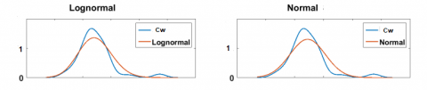
For the coefficient cw the comparison of the normal probability density distribution will be as Figure 12.
At the same time, for cw we similarly obtain a band of uncertainty: the lower limit is 1.024, the upper limit is 1.034. The authors would like to note that during the experiment, the values ΔT for the coefficient cw were studied from the data obtained, based on the sample. The values ΔT obtained include the effects of external factors, the total standard deviation was estimated, and a sensitivity analysis was performed.
Table 4. Dependency of the coefficient $\mathrm{c}_{\mathrm{W}}$ on the temperatures of cold and heated air for a coil-type steam boiler
|
|
With the coldest five days |
At the average temperature of the coldest month |
At the air temperature t=+8 ${ }^{\circ} \mathbf{C}$ |
|
|
[ ${ }^{\circ} \mathbf{C}$] |
[ ${ }^{\circ} \mathbf{C}$] |
[ ${ }^{\circ} \mathbf{C}$] |
|
$T_{c. a}$ |
-40 |
-25 |
+8 |
|
$T_{\text {h.a }}$ |
+27 |
+58 |
+65 |
|
$\mathrm{c}_{\mathrm{W}}$ |
1.029 |
1.026 |
1.032 |
(a) Lognormal
(b) Normal
Figure 12. Normal distribution of probability density coefficient cw
Scientific developments of Mikhaylenko, carried out relatively recently, show that the theory of heat and mass transfer, in particular the movement of flows of gases and liquids, has its drawbacks as applied to experimental studies of boiler installations. Mikhaylenko presented the research results in the form of a developed model [22]. Researchers, for example Sweetnam et al. [3] proposed a hypothesis of the behavior of air flow on a weakly non-isothermal model, as well as in computer simulation of the motion of heated gases, and this hypothesis was partially confirmed by the developed mathematical model. The hypotheses considered in the review were confirmed by constructing mathematical models. These models are fully consistent with each other, as well as with the basic physical laws, in particular the equations of conservation of mass and energy, as well as the boundary conditions of heat exchange and gas-dynamic processes.
Hameed et al. propose mathematical models that are applicable to the hydro- and gas dynamics of boiler units of similar designs [23, 24]. And Trojan [25] proposes a non-standard mathematical model applicable to a steam generator. Orlov [26] offer a whole software package for calculating the hydrodynamics of a boiler unit.
All of these works have their own disadvantages and advantages. At the same time, since the boiler unit considered in this article is unique, it is difficult to make an exact match based on the results of scientific analysis of developments and models. The authors of this article, in fact, develop specific mathematical models that are applicable to a new type of steam generator.
Let's compare the data obtained by different authors, for example, on the hydrodynamics of water in a boiler unit, Table 5.
Table 5. Comparison of the experimental data of the authors at a temperature of 120℃
|
Speed (experiment), m / s |
According to the authors |
According to Orlov [26] |
According to Hag et al. [12] |
|
w |
4.08 |
4.10 |
4.09 |
Coil-type steam boilers have withstood operation at the northern oil field "Var-Yogan" as part of a modernized boiler plant.
The results of our analysis of the experimental data collected from the MTPB in real working conditions allow us to draw the following particular conclusions that are of interest to this experimental theoretical study:
(1) We introduce correction factors for the equation of the convective component of radiant-convective heat transfer in the gas ducts. With these correction factors, $\mathrm{Q}_{\mathrm{f}}$ is close to the real value, taking into account the design features of the boiler. The results of the dependence of the correction factor $\mathrm{c}_{\mathrm{W}}$ on the temperature of the outside and heated air are presented.
(2) During experimental operation, the advantages of the compact design of the boilers were proven.
(3) Testing the boiler plant showed that a stable fuel temperature provided the required viscosity and good fuel atomization. Along with the change in the consumption of feed water and fuel, there was a significant change in temperature and steam pressure due to the low storage capacity of the once-through boilers. Losses with underburning and outgoing heat have decreased.
(4) For the first time, experimental coefficients have been obtained that can be used for direct-flow steam generators of the coil type, which will increase the efficiency of these heat exchange devices.
(5) The experimental data passed the sensitivity analysis, including the obtained a band of uncertainty, the method was validated. The experimental and simulation data are compared with the results of other authors.
(6) The prospects for the operation of direct-flow coil-type boilers are associated, first of all, with the spread of their applicability to the difficult operating conditions of industrial enterprises and drilling rigs located in regions of the subarctic climate. Based on the results of the experimental work, it is possible to outline a tendency to use such installations in the Arctic climate.
(7) The principle of operation of such installations should be extended to heat exchange devices in various areas of industrial production, such as chemical and agricultural. In such enterprises, coil-type heat exchangers are indeed required, and the set of experimental data obtained and the developed test methodology can be used as a basis for new scientific research.
|
B |
fuel consumption, kg. s-1 |
|
ct |
temperature correction |
|
$C_{w}$ |
coefficient, which summarizes the correction factors used in deviations for the cold air temperature and after the air heater |
|
cf |
correction factors for flow turbulization and for the variable value of the equivalent diameter of annular channels formed by coaxial cylindrical |
|
D |
diameters of the coaxial cylinders of the coils, m |
|
F1 |
internal surface area of the furnace, m2 |
|
G |
water consumption, kg. s-1 |
|
HF |
height of the furnace, m |
|
h'' |
enthalpy of steam, MJ. kg-1 |
|
hfw |
enthalpy of feed water, MJ. kg-1 |
|
k |
heat transfer coefficient |
|
$k_{a . h}$ |
correction factor |
|
NCV |
net calorific value of fuel, MJ |
|
ps |
steam pressure after the boiler, MPa |
|
Qf |
convective component of radiant-convective heat exchange |
|
$q_{2}$ |
heat loss with exhaust gases, % |
|
Tc.a |
temperature of cold air, ℃ |
|
Th.a |
temperature of hot air, ℃ |
|
Tw |
water temperature, °C |
|
Ts |
steam temperature after the boiler, ℃ |
|
Tgas |
gas temperature, ℃ |
|
Tgas' |
characteristic temperature of the gas-air flow, ℃ |
|
Tw1 |
average temperature of the furnace wall, ℃ |
|
Tair |
air temperature, ℃ |
|
$t_{c. a i r}^{\text {calc }}$ |
cold air temperature, calculated, ℃ |
|
$t_{c . a i r}^{e x p}$ |
cold air temperature, experimental value, ℃ |
|
$t_{a . h}^{c a l c}$ |
air temperature after the air heater, calculated, ℃ |
|
$t_{a . h}^{\exp }$ |
air temperature after the air heater, experimental value, ℃. |
|
Greek symbols |
|
|
ac |
the heat transfer coefficients by convection |
|
ar |
heat transfer coefficients by radiation |
|
∆T |
difference between cold and hot air, ℃ |
|
ΔB |
fuel consumption change, kg. s-1 |
|
Δt |
temperature change, ℃ |
|
$\Delta q_{2}^{c . a i r}$ |
correction for deviation of cold air temperature, % |
|
$\Delta q_{2}^{a . h}$ |
change in $q_{2}$ values when heating air in the air heater by $\Delta \mathrm{T}_{\mathrm{gf}}, \%$ |
|
η |
boiler efficiency, % |
|
$\Sigma k_{t} \Delta m$ |
sum of the products of the correction factors for the deviation of the initial parameter by ∆m, nominal or calculated, % |
|
$\vartheta_{e x}$ |
flue gas temperature, ℃ |
|
$\Psi$ |
beam thermal efficiency coefficient |
[1] Arnfield, A.J. (2020) Köppen Climate Classification, Encyclopædia Britannica. Encyclopædia Britannica, inc.; 2020. https://www.britannica.com/science/Koppen-climateclassification.
[2] Bennett, G.J., Elwell, C.A., Oreszczyn, T. (2019). Space heating operation of combination boilers in the UK: The case for addressing real-world boiler performance building services. Engineering Research and Technology, 40(1): 75-92. https://doi.org/10.1177/0143624418794552
[3] Sweetnam, T., Spataru, C., Barrett, M., Carter, E. (2019). Domestic demand-side response on district heating networks. Building Research and Information, 47(4): 330-343. https://doi.org/10.1080/09613218.2018.1426314
[4] Hernández Corona, J.L., Vázquez, E.M., Sánchez Lima, H., Fragoso Parra, V., Espinoza Peralta, G.A., Olivares Bautista, J.A. (2020) Steam generator for external resistances. International Journal of Scientific and Research Publications, 10(11): 463-469. http://dx.doi.org/10.29322/IJSRP.10.11.2020.p10759463-469
[5] Guidez, J., Prêle, G. (2017) The Steam Generators. In: Superphenix. Atlantis Press, Paris. https://doi.org/10.2991/978-94-6239-246-5_12
[6] Sharma, A., Sharma, M., Shukla, A.K., Negi, N. (2019) Evaluation of heat recovery steam generator for gas/steam combined cycle power plants. Advances in Fluid and Thermal Engineering, pp. 189-200. https://doi.org/10.1007/978-981-13-6416-7_18
[7] Astorga-Zaragoza, C.M., Osorio-Gordillo, G.L., Reyes-Martínez, J., Madrigal-Espinosa, G., Chadli, M. (2018). Takagi-Sugeno observers as an alternative to nonlinear observers for analytical redundancy. Application to a steam generator of a thermal power plant. International Journal of Fuzzy Systems, 20: 1756-1766. https://doi.org/10.1007/s40815-018-0481-8
[8] Silva, P.R.S., Leiroz, A.J.K., Cruz, M.E.C. (2020). Evaluation of the efficiency of a heat recovery steam generator via computational simulations of off-design operation. Journal of the Brazilian Society of Mechanical Sciences and Engineering, 42: 569. https://doi.org/10.1007/s40430-020-02655-1
[9] Deghal Cheridi, A.L., Loubar, A., Dadda, A., Bouam, A. (2019). Modeling and simulation of a natural circulation water-tube steam boiler. SN Applied Sciences, 1: 1405. https://doi.org/10.1007/s42452-019-1452-x
[10] Moghari, M., Hosseini, S., Shokouhmand, H., Sharifi, H., Izadpanah, S. (2012). A numerical study on thermal behavior of D-type water cooled steam boiler. Applied Thermal Engineering, 37: 360-372. https://doi.org/10.1016/j.applthermaleng.2011.11.049
[11] Sunil, P.U., Barve, J., Nataraj, P.S.V. (2017). Mathematical modeling, simulation and validation of a boiler drum: Some investigations. Energy, 126: 312-325. https://doi.org/10.1016/j.energy.2017.02.140
[12] Haq, E.E.U., Rahman, E.T.U., Ahad, E.A, Ali, E.F., Ijaz, E.M. (2016). Modeling and simulation of an industrial steam boiler. International Journal of Computer Engineering and Information Technologies, 8(1): 7-10.
[13] Backi, C.J. (2018). Nonlinear modeling and control for an evaporator unit. Control Engineering Practice, 78: 24-34. https://doi.org/10.1016/j.conengprac.2018.06.006
[14] Chauhan, S.S., Khanam, S. (2018). Energy integration in boiler section of thermal power plant. Journal of Cleaner Production, 202: 601-615. https://doi.org/10.1016/j.jclepro.2018.08.161
[15] Shi, Y., Wang, J. (2015). Ash fouling monitoring and key variables analysis for coal fired power plant boiler. Thermal Science, 19(1): 253-265. https://doi.org/10.2298/tsci120428118s
[16] Kuznetsov, N.V. (2011). Thermal calculation of boiler units: Standard method. M.: EKOLIT. (in Russian).
[17] Lummi, A.P. (2009). Calculation of a hot water boiler. Yekaterinburg: GOU VPO USTU-UPI. (in Russian).
[18] Toropov, E.V., Osintsev, K.V., Aliukov, S.V. (2018). Analysis of the calculated and experimental dependencies of the combustion of coal dust on the basis of a new methodological base of theoretical studies of heat exchange processes. International Journal of Heat and Technology, 36(4): 1240-1248. https://doi.org/10.18280/ijht.360411
[19] Toropov, E.V., Osintsev, K.V., Aliukov, S.V. (2019). New theoretical and methodological approaches to the study of heat transfer in coal dust combustion. Energies, 12(1): 136. https://doi.org/10.3390/en12010136
[20] Alabugin, A., Aliukov, S., Osintsev, K. (2021). Combined approach to analysis and regulation of thermodynamic processes in the energy technology complex. Processes, 9(2): 204. https://doi.org/10.3390/pr9020204
[21] Osintsev, K., Aliukov, S., Prikhodko, Y. (2020). New methods for control system signal sampling in neural networks of power facilities. IEEE Access, 8: 192857-192866. https://doi.org/10.1109/ACCESS.2020.3032326
[22] Mikhaylenko, E.V. (2015). How to improve the characteristics of mobile generators. Chief Power Engineer, 5-6: 65-71. (in Russian).
[23] Hameed, V., Hamad, F.J. (2020). Investigation study of vertical helical coil heat exchanger. Conference: The Second International Conference on Materials Engineering and Science, 2213(1): 020093. https://doi.org/10.1063/5.0000219
[24] Boje, E. (2009). Dry-out point estimation in once through boilers. Conference: System Identification, 42(10): 723-728. https://doi.org/10.3182/20090706-3-FR-2004.00120
[25] Trojan, M. (2019). Modeling of a steam boiler operation using the boiler nonlinear mathematical model. Energy, 175(15): 1194-1208. https://doi.org/10.1016/j.energy.2019.03.160
[26] Orlov, K.A. (2002). Program complex "WaterSteamPro" for calculating the thermophysical properties of water and water vapour. X Russian Conference on thermophysical properties of substances: Abstracts of reports. Kazan: Publishing house "Butlerov communications". (in Russian).