Sai Sarath Kruthiventi | Nandhanagopal Govindha Rasu* | Yarrapathruni V. Hanumanth Rao
© 2021 IIETA. This article is published by IIETA and is licensed under the CC BY 4.0 license (http://creativecommons.org/licenses/by/4.0/).
OPEN ACCESS
In the present study, numerical analysis of coiled tube heat exchanger used in J-T refrigerator is carried out. A computer code is developed to estimate the length of the heat exchanger by giving mass flow rate, diameter of tube and shell as input parameters. This code is verified against experimental data. Two different configurations are considered in this study viz., heat exchanger with wire fin wound around the inner tube of heat exchanger and without wirefin. Three different refrigerant mixtures are used to evaluate the performance of heat exchangers. The variations of temperature and heat transfer coefficient are brought out as result. Significant reduction in the length of heat exchanger is observed in all the cases. Mixture-1 causes 33% reduction in length of heat exchanger with wirefin. Similarly, for mixture-2 and mixture-3 the length is reduced by 15% and 30%. Additionally, heat transfer coefficient (HTC) values are also estimated for heat exchanger with wirefin and without wirefin. Considerable increase in HTC values is observed in the heat exchanger with wirefin.
J-T refrigerator, wirefin, coiled tube heat exchanger, refrigerant mixture
Heat exchangers are one of the most critical components of any cryogenic refrigerator. A small ineffectiveness of the heat exchanger results in significant percentage of decrease in the performance of the refrigerator [1]. Coiled tube heat exchangers are widely used in small J-T refrigerators (heat capacities are typically less than 10 W) due to simplicity in their construction, less space occupancy and low longitudinal heat conduction [1]. Ardhapurkar et al. [2] conducted series of experiments on multiple tubes-in-tube heat exchanger. Based on the mixture composition they stated the performance of heat exchanger in terms of overall heat transfer coefficient along the length of heat exchanger. Few researchers have investigated experimental and numerical studies related to usage of mixed refrigerants in J-T refrigerators, but paid attention on optimizing the mixture composition [3-8]. Moreover very limited literature is available about the performance analysis of coiled tube-in-tube heat exchangers. Many researchers have worked to analyze the steadystate performance of the Joule Thompson cryocooler [9-12]. Limited studies also stated on transient analysis in the literature [13-15]. Modified Granryd correlation is applied for boiling [16]. Few correlations provided by Shah [17], Dobson and Chato [18] and Cavalline and Zechin [19] are used for condensation. Gong et al. [8] conducted series of experiments for different mixtures and provided experimental data in terms of pressure drop and temperature profiles for a tube-in-tube heat exchanger. Simulation studies on tubes-in-tube heat exchanger for various mixtures was done by Alexeev et al. [6]. Moreover, most of the results obtained were not compared with experimental data available in the literature. Ardhapurkar et al. [20] made a comparison between the existing heat transfer correlations and the experimental results available in the literature. Apart from the stated advantages, coiled tube heat exchangers may also suffer from the touching of tube walls with shell wall which leads to flow mal distribution on the shell side of the heat exchanger, which in turn reduces the performance of the heat exchanger [1]. Heat Exchanger designers always search for new methods to improve the life time of heat exchanger and heat transfer efficiency [21]. One way to overcome the above problem is to use a wire over the inner tube which separates the tubes from other tubes as well as shell wall. Winding wire will also improve the turbulence on the shell side and helps in improvement of rate of heat transfer. Such heat exchangers are used earlier [22, 23] but their design procedures are not revealed. The design procedures for such heat exchanger are also limited in literature. The reason for this is the existence of the operating fluid in two phase (condensation heat transfer on one side and boiling heat transfer on the other side). One of the objectives of present paper is to theoretically design a coiled wire finned tube heat exchanger using existing single phase and two phase heat transfer models. The second objective is to compare the size of heat exchanger with wirefin and without wirefin wound over inner tube. Heat exchanger with fin and without fin are considered and their HTC values are evaluated and compared to conclude about the results caused usage of fin. A comparison is made between these values of HTCs with and without wire fin for different mixtures. In the present study a coiled wire finned heat exchanger whose length varies typically from 0 to 15000 mm and diameter varies from 4.83 mm to 9.52 mm is studied. Earlier these heat exchangers were used in helium liquefaction whereas in our study these heat exchangers are operated with hydrocarbon based mixtures.
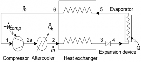
The schematic diagram of cold section of Joule-Thomson refrigerator is presented in Figure 1. It is working with constituents, such as Nitrogen-Hydrocarbon mixtures. Refrigerant mixture enters into the compressor at low pressure and it is denoted by state 1. During this process the temperature and pressure of the mixed refrigerant increases. In order to maintain constant temperature, an aftercooler is placed at the exit of the compressor. The refrigerant mixture then passes through the aftercooler from the state of 2a to state 2. Later the mixture is allowed into the recuperative heat exchanger unit at state 2 and comes out at state 3 after partial condensation process. Refrigerant mixture condenses partially during the process 2-3 by rejecting heat to the same refrigerant mixture which is at lower temperature that is coming out from the evaporator. Partial evaporation process takes place in the evaporator during 4-5 process. Thus, condensation and boiling takes place in the heat exchanger during the processes 2-3 and 5-6 simultaneously. Complete operation repeats subsequently which constitutes a cyclic process. Many studies are available in the open literature on predicting the heat transfer coefficients of pure fluids. Further there are studies in which the same pure fluid two phase heat transfer models were made use of to predict the heat transfer coefficients of the mixtures [14]. Optimization studies for mixture composition is carried out elsewhere to obtain higher exergy h [24, 25].
Table 1 gives the details of the coiled tube heat exchanger used in the study of Ardhapurkaret al. [20]. The total length of the heat exchanger is about 15 m with a coil diameter of 0.2 m. Details of the composition of the mixtures used to obtain temperatures of the order of 100K [20] is presented in Table 2. Details of the operating parameters for different mixtures are presented in Table 3. Ardhapurkar et al. [2] in their earlier study used coiled tube-in-tube heat exchanger as the recuperative heat exchanger in the J-T refrigerator. The reason for such longer length for the heat exchanger of 15 m is due to the large temperature glide of the working fluids on both sides of the heat exchanger (typically 200 K). Longer length of the heat exchanger not only involves extra cost but also act as inventory or flammable refrigerant. In present study, we proposed to use a tube-in-tube heat exchanger with wire fin wound around the tube. Wire fin increases the turbulence as shell side and also improves the rate of heat transfer. The details of heat exchanger considered in this study are given in the Table 1. The details of the wire fin considered in our study are $\frac{d_{W}}{d_{e s}}=0.08, \frac{t_{f}}{d_{w}}=4.2 \frac{d_{2}}{d_{e s}}=0.8$.
Figure 1. Joule Thompson refrigerator operating in GRS mode [26]
Table 1. Geometric details of heat exchanger [20]
|
Parameter (Unit) |
Size (mm) |
|
Heat exchanger length (mm) Diameter of the coil (mm) Pitch of the coil (mm) No. of turns Inner diameter of the Inner tube, (mm) Outer diameter of the Inner tube, (mm) Inner diameter of outer tube, (mm) Outer diameter of the Outer tube, (mm) |
15000 200 14.5 23 4.83 6.35 7.89 9.52 |
Table 2. Specifications of the mixture [20]
|
Mixture number |
Composition of the Mixture CH4/C3H8/N2/C2H6/iC4H10 (% mol) charged |
Composition of the mixture CH4/C3H8 /N2 / C2H6/iC4H10 (%mol) circulation |
Range in temperature (K) |
|
Mix#1 |
42.5/5.0/5.5/42.5/11.0 |
46.335/3.996/6.990/6.335/9.146 |
140-150 |
|
Mix#2 |
15.0/19.0/36.0/13.0/17.0 |
16.865/17.380/39.860/12.840/13.045 |
<100 |
|
Mix#3 |
31.0/21.0/15.5/16.5/16.0 |
32.785/20.140/18.455/16.050/12.570 |
110-120 |
Table 3. Working parameters for the mixtures used [1]
|
Mixture |
Tlow (K) |
m (g/s) |
Phn (bar) |
Th.in (K) |
Pc.in (bar) |
Tc.in (K) |
Ph.out (bar) |
Pc.out (bar) |
|
Mix#1 |
143.98 |
3.80 |
12.38 |
303.18 |
6.11 |
144.87 |
11.41 |
3.20 |
|
Mix#2 |
98.62 |
3.70 |
14.74 |
301.50 |
5.61 |
100.17 |
13.95 |
2.60 |
|
Mix#3 |
113.45 |
2.64 |
11.70 |
302.66 |
5.57 |
114.83 |
11.01 |
2.30 |
Table 4. Two phase heat transfer models used in this work to estimate two phase heat transfer coefficients
|
S.No |
Reference |
Correlation |
|
1 |
Shah correlation (1982) |
htp=larger of hc and hnb, $h_{c}=1.8 h_{l} \mathrm{CO}^{-0.8}$, |
|
2 |
Kandilkar (1983) |
$\frac{h_{t p}}{h_{l}}=D_{1}(c o)^{D_{2}}\left(25 F r_{l o}\right)^{D_{5}}+D_{3}(B o)^{D_{4}}\left(25 F r_{l o}\right)^{D_{6}}$ |
|
3 |
Gungor and Winterton (1987) |
$h_{t p}=E_{n e w} \times h_{l o}, E_{n e w}=1+3000 B o^{0.86}+1.12\left(\frac{x}{1-x}\right)^{0.75}\left(\frac{\rho_{l}}{\rho_{v}}\right)^{0.41}$ |
|
4 |
Liu (1991) |
$h_{t p}=\sqrt{\left(F \times h_{l}\right)^{2}+\left(s \times h_{n b}\right)^{2}}$ |
|
5 |
Steiner (1992) |
$h_{t p}=\left(h c^{3}+h_{n b}^{3}\right)^{1 / 3}, h_{c}=\mathrm{h}_{l}\left(\varphi_{1}+\varphi_{2}\right)^{-0.5}$ |
|
6 |
Little (2008) |
$\frac{1}{h_{c m}}=\frac{1}{h_{l}}+\frac{x^{2}\left(C_{p_{v}} / C_{p_{\text {total }}}\right)}{\left(\frac{\partial H}{\partial T}\right)_{p} / C_{p_{v}}}$ |
For the enhancement of heat exchanger performance based on composition of mixture, a wirefin is wound around the inner tube of the heat exchanger. Temperature profiles are drawn with respect to length of heat exchanger for both hot fluid and cold fluid and also heat transfer coefficients are estimated for both shell side and tube side with respect to quality. Heat transfer coefficients are calculated at different sections of the heat exchanger by using two phase heat transfer models which are defined below. Martynov and Krasnikova [27] conducted studies on coiled wire finned hx that are used in Helium liquification. They developed correlations for estimating the single phase heat transfer coefficient in wire finned heat exchanger and hx considered in the present study. Therefore, the same correlations are used in this work. The correlation is given as follows [27].
$\begin{align} & J=178.2*10-2*(\frac{\partial w}{\partial es})1.36(\frac{tf}{\partial w})-0.057(\frac{\partial z}{des})0.414(\operatorname{Re}s)n)/40,000 \\ \end{align}$
In the present work, a computer code has been developed to compare the numerical values of temperatures estimated for the hot and cold streams with the available experimental values in the literature. The code is flexible to calculate the temperature variations for different mixtures. The input values like mass, diameter of tube, diameter of shell, hot fluid inlet and cold fluid inlet temperatures are given as inputs in the code for 3 different mixtures and the results are verified for temperatures difference, and heat transfer coefficients. For each mixture, six different correlations are tested, as presented in Table 4.
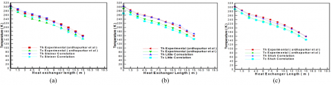
Figure 2 shows the temperature profiles that are compared with the existing experimental values. The experimental and numerically predicted values agreed well for all the 6 correlations used, where as it has been observed from the Figure 2 that the DTh and DTcvalues are minimum in the Gungor and Winterton correlation for the mixture 1. From the Figure 2(e) it is clearly seen that the maximum temperature difference (DT) for hot stream in mixture1 is about 3K, and it is observed at x = 13.5 m, and (DT) also for cold stream is 3K, observed at x =13.5 m. This indicates that all the other temperature differences at other locations of the length are below 3K. Similar behaviour is observed for the other two mixtures (mixture 2 and mixture 3). From this we can say that Gungor & Winterton correlation is suitable for the developed computer programme.
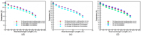
The temperature profiles when wirefin is wound around the inner tube of the heat exchanger is presented in Figure 3, where in a considerable change in the length has been recorded. A noticeable decrease in the length for different models are observed. Whereas Gungor and Winterton is presented here. The length of heat exchanger without fin in each case is considered at 15 m. For mixture 1, the length has reduced to 9.78 m on using a fin which accounts to about 33% reduction in length. For mixture 2, the reduction in length is 15% which is 12.68 m. For mixture 3 also a significant reduction in length of heat exchanger is observed on using a fin. The length reduced to 10.38 m from 15 m which accounts to 30.8% reduction. It is also clearly observed that there is a qualitative variation of temperature for all the mixtures. Comparison of profiles for all the correlations reveals that they are varying proportionally with a uniform difference in temperature and it is because of specific heat comparisons of two different fluid streams. However, the slope of profiles has drastically reduced at the beginning (warm end) for Kandilkar correlation. This may be due to larger liquid fractions because of methane.
Figure 2. Validation of experimental and numerical values of the temperatures with respect to change in length of the heat exchanger for mixture 1
Figure 3. Variation of temperature with the length of heat exchanger (a) Mixture 1 (b) Mixture 2 and (c) Mixture 3
Table 5. Heat transfer coefficients values with wire fin and without wirefin for both shell and tube side
|
Mix No |
Shell side (HTC) without fin (W/m2-K) |
Shell side (HTC) with fin (W/m2-K) |
% change |
Tube Side (HTC) without fin (W/m2-K) |
Tube Side (HTC) with fin (W/m2-K) |
% change |
|
1 |
1671 |
1366 |
-22 |
1852 |
2962 |
59 |
|
2 |
1075 |
1085 |
1 |
1517 |
2094 |
38 |
|
3 |
828 |
1033 |
25 |
1495 |
1658 |
11 |
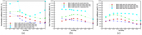
Figure 4. Comparison of heat transfer coefficients with and without wire fin at various quality points for all the three mixtures
Details of heat transfer coefficients (HTCs) values is presented in Table 5. For this purpose heat exchanger with fin and without fin are considered and their HTC values are evaluated and compared to conclude about the results caused usage of fin. Now, a comparison is made between these values of HTCs with and without wire fin for different mixtures i.e., mixture1 mixture2, mixture3 and also for both shell side and tube side. Corresponding to each mixture, again the shell side HTC and tube side HTC are calculated and compared with the respective HTCs of heat exchanger without fin. From the Figure 4, it is clearly seen that for all the three mixtures a noticeable increase in the values of HTC is observed in using a wire fin. Compared to shell side, tube side HTC values increased drastically. It is observed that 58% increase in tube side HTC for mixture 1, and a considerable improvement is seen for other two mixtures. Hence by using wirefin, the heat transfer coefficients can be increased to a great extent for all the three mixtures. This is because of the dependence of heat transfer coefficient values on the composition of mixture and also the input parameters like mass flow rate and pressure of the mixture. It is clearly seen from the figures ‘M’ shape variation is observed for the graphs with and without wirefin and it is due to mixture of various gases used.
Numerical analysis of heat exchanger used in J-T refrigerator which works on the hydrocarbon refrigerant mixtures is presented in this paper. Present computer code is verified with the existing experimental data. It is observed that the maximum temperature difference of 3K between experimental and numerical model. Two different configurations are studied in this study viz., heat exchanger with wire fin wound around the inner tube of heat exchanger and without wirefin. Three different refrigerant mixtures are used to evaluate the performance of heat exchangers. The variations of temperature and heat transfer coefficient are brought out. It is clearly observed that for all the mixtures, there is a significant reduction in the length of heat exchanger. Mixture-1 causes 33% reduction in length of heat exchanger with wirefin. Similarly, for mixture-2 and mixture-3 the length is reduced by 15% and 30%. Additionally, heat transfer coefficient (HTC) values are also estimated for heat exchanger with wirefin and without wirefin. There is a considerable increase in HTC values observed when a wirefin is wound around the inner tube of heat exchanger.
|
Specifications |
|
|
ID |
Inner diameter (mm) |
|
OD |
Outer diameter (mm) |
|
Greek symbols |
|
|
h |
Efficiency |
|
$\sigma$ |
Surface tension, N/m |
|
$\rho$ |
Mass density, kg/m3 |
|
Subscripts |
|
|
tp |
two phase |
|
nb |
nucleate boiling |
|
m |
mixture |
|
g |
Gas |
|
lo |
Liquid only |
|
l |
Liquid |
|
v |
Vapour |
|
p |
pressure |
|
c |
Convection |
|
Notations |
|
|
A |
Cross sectional area (m2) |
|
C |
Enhancement factor |
|
Cpw |
Apparent local specific heat (J/kg-k) |
|
Cpv |
specific heat of vapour (J/kg-k) |
|
Cv |
Control volume |
|
E |
Two phase convection multiplier |
|
F |
Flow boiling |
|
G |
Mass velocity (kg/m2 s) |
|
h |
Heat transfer coefficient(w/m2-k) |
|
hx |
heat exchanger |
|
j |
Heat emission |
|
k |
Thermal conductivity (W/m-K) |
|
q |
Heat flux (W/m2) |
|
S |
Forced convection suppression parameter |
|
T |
Temperature (K) |
|
x |
Quality |
|
dw |
Wire diameter |
|
des |
Equivalent diameter |
|
tf |
Fin spacing |
|
$\Delta T_{h}$ |
Hot fluid temperature difference |
|
$\Delta T_{c}$ |
Cold fluid temperature difference |
|
dw/des |
Relative fin spacing |
|
tf /dw |
Relative tube diameter |
|
nt |
Function of relative surface roughness |
|
D1 |
Internal diameter of tube (mm) |
|
D2 |
External diameter of tube (mm) |
|
$\varphi$ |
Steiner Parameter |
|
Non-dimensional numbers |
|
|
Bo |
Boiling number |
|
Pr |
Prandtl number |
|
Re |
Reynolds number |
|
F |
Froud number |
[1] Damle, R.M., Ardhapurkar, P.M., Atrey, M.D. (2015). Numerical analysis of the two-phase heat transfer in the heat exchanger of a mixed refrigerant Joule-Thomson cryocooler. Cryogenics, 72: 103-110. https://doi.org/10.1016/j.cryogenics.2015.09.010
[2] Ardhapurkar, P., Sridharan, A., Atrey, M. (2012). Investigations on two-phase heat exchanger for mixed refrigerant Joule-Thomson cryocooler. AIP Conference Proceedings, 1434(1): 706-713. https://doi.org/10.1063/1.4706982
[3] Brodyanskii, V.M., Gromov, E.A., Grezin, A.K., Yagodin, V.M., Nikol’skii, V.A., Tashchina, A.G. (1971). Efficient throttling cryogenic refrigerators which operate on mixtures. Chem Petrol Eng., 7(12): 1057-1061. https://doi.org/10.1007/BF01138079
[4] Longsworth, R.C., Boiarski, M.J., Klusmier, L.A. (1995). 80 K closed-cycle throttle refrigerator. Cryocoolers, 8: 537-541. https://doi.org/10.1007/978-1-4757-9888-3_55
[5] Walimbe, N.S., Narayankhedkar, K.G., Atrey, M.D. (2010). Experimental investigation on mixed refrigerant Joule-Thomson cryocooler with flammable and non-flammable refrigerant mixtures. Cryogenics, 50(10): 653-659. https://doi.org/10.1016/j.cryogenics.2010.06.002
[6] Alexeev, A., Haberstroh, C., Quack, H. (1998). Further development of a mixed gas Joule Thomson refrigerator. In Advances in cryogenic engineering. Advances in Cryogenic Engineering, 43: 1667-1674.
[7] Keppler, F., Nellis, G., Klein, S.A. (2004). Optimization of the composition of a gas mixture in a Joule-Thomson cycle. HVAC&R Research, 10(2): 213-230. https://doi.org/10.1080/10789669.2004.10391100
[8] Gong, M.Q., Luo, E.C., Zhou, Y., Liang, J.T., Zhang, L. (2000). Optimum composition calculation for multicomponent cryogenic mixture used in Joule-Thomson refrigerators. Advances in Cryogenic Engineering, (45): 283-290.
[9] Ng, K.C., Xue, H., Wang, J.B. (2002). Experimental and numerical study on a miniature Joule–Thomson cooler for steady-state characteristics. International Journal of Heat and Mass Transfer, 45(3): 609-618. https://doi.org/10.1016/S0017-9310(01)00165-X
[10] Xue, H., Ng, K.C., Wang, J.B. (2001). Performance evaluation of the recuperative heat exchanger in a miniature Joule-Thomson cooler. Applied Thermal Engineering, 21(18): 1829-1844. https://doi.org/10.1016/S1359-4311(01)00050-3
[11] Hong, Y.J., Park, S.J., Choi, Y.D. (2010). A numerical study on the performance of the miniature Joule-Thomson refrigerator. AIP Conference Proceedings, 1218(1): 103-110. https://doi.org/10.1063/1.3422265
[12] Chua, H.T., Wang, X., Teo, H.Y. (2006). A numerical study of the Hampson-type miniature Joule-Thomson cryocooler. International Journal of Heat and Mass Transfer, 49(3-4): 582-593. https://doi.org/10.1016/j.ijheatmasstransfer.2005.08.024
[13] Chou, F.C., Pai, C.F., Chien, S.B., Chen, J.S. (1995). Preliminary experimental and numerical study of transient characteristics for a Joule-Thomson cryocooler. Cryogenics, 35(5): 311-316. https://doi.org/10.1016/0011-2275(95)95349-J
[14] Chien, S.B., Chen, L.T., Chou, F.C. (1996). A study on the transient characteristics of a self-regulating Joule-Thomson cryocooler. Cryogenics, 36(12): 979-984. https://doi.org/10.1016/S0011-2275(96)00085-9
[15] Hong, Y.J., Park, S.J., Kim, H.B., Choi, Y.D. (2006). The cool-down characteristics of a miniature Joule-Thomson refrigerator. Cryogenics, 46(5): 391-395. https://doi.org/10.1016/j.cryogenics.2005.07.008
[16] Granryd, E. (1991). Heat transfer in flow evaporation of nonazeotropic refrigerant mixtures a theoretical approach. In 18th International Congress of Refrigeration, Montreal, QC, Canada, pp. 10-17.
[17] Shah, M.M. (1979). A general correlation for heat transfer during film condensation inside pipes. Journal of Heat Mass Transfer, 22(4): 547-556. https://doi.org/10.1016/0017-9310(79)90058-9
[18] Dobson, M.K., Chato, J.C. (1998). Condensation in smooth horizontal tubes. Journal of Heat Transfer Transactions ASME, 120(1): 193-213. https://doi.org/10.1115/1.2830043
[19] Cavallini, A., Zecchin, R. (1974). A Dimensionless Correlation for Heat Transfer in Forced Convection Condensation. In Proc. 5th International Heat Transfer Conference, pp. 309-313. https://doi.org/10.1615/IHTC5.1220
[20] Ardhapurkar, P.M., Sridharan, A., Atrey, M.D. (2014). Experimental investigation on temperature profile and pressure drop in two-phase heat exchanger for mixed refrigerant Joule-Thomson cryocooler. Applied Thermal Engineering, 66(1-2): 94-103. https://doi.org/10.1016/j.applthermaleng.2014.01.067
[21] Buonomo, B., Pasqua, A., Manca, O., Nardini, S. (2019). Numerical study on thermal and fluid dynamic behavior of a compact heat exchanger partially filled with metal foam. TECNICA ITALIANA-Italian Journal of Engineering Science, 63(2-4): 336-342. https://doi.org/10.18280/ti-ijes.632-432
[22] Ardhapurkar, P.M., Sridharan, A., Atrey, M.D. (2014). Flow boiling heat transfer coefficients at cryogenic temperatures for multi-component refrigerant mixtures of nitrogen--hydrocarbons. Cryogenics, 59: 84-92. https://doi.org/10.1016/j.cryogenics.2013.11.006
[23] Ardhapurkar, P.M., Sridharan, A., Atrey, M.D. (2014). Performance Evaluation of heat exchangers for mixed refrigerant J-T cryocooler. Cryogenics, 63: 49-56. https://doi.org/10.1016/j.cryogenics.2014.06.012
[24] Kruthiventi, S.S., Govindha Rasu, N., Hanumantha Rao, Y.V. (2018). An identification of the best mixture composition for the Joule Thompson refrigerator operating at 90 K. International Journal of Mechanical and Production Engineering Research and Development, 8(5): 467-476.
[25] Kruthiventi, S.S., Govindha, R.N., Hanumantha Rao, Y.V. (2019). Influence of wire fin on performance of coiled tube heat exchanger in a small J-T refrigerator. 2nd International Conference on New Frontiers in Chemical, Energy and Environmental Engineering (Inceee - 2019), NIT, Warangal, India.
[26] Venkatarathnam, G. (2008). Cryogenic Mixed Refrigerant Processes. New York (NY).
[27] Martynov, V.A., Krasnikova, O.K. (1987). Thermal hydrodynamic characteristics of coil heat exchangers of the throttle stage of cryogenic helium plants. Chemical and Petroleum Engineering, 23(1): 24-28.