Ting Yang | Yi Hong* | Aijun Wang | Xiaofeng Ran | Xiaojun Fan | Changpeng Hu
© 2021 IIETA. This article is published by IIETA and is licensed under the CC BY 4.0 license (http://creativecommons.org/licenses/by/4.0/).
OPEN ACCESS
Throttle valve is an important device in well control manifold. In the process of field use, the valve seat and plug of the valve often have corrosion failure, which brings serious potential safety hazards to the well control work. Using the three-dimensional flow field analysis software of computational fluid dynamics (CFD), it is found that the velocity on the left wall is greater than that on the right. The field failure investigation also proved that the erosion damage mainly occurred on the left wall of the throttle valve, which verified the failure causes of the throttle valve core and valve seat. In addition, the flow field of the erosion resistance device is numerically simulated. The results show that under the given boundary conditions, when the fluid passes through the inlet and outlet of the erosion resistance device, the average velocity changes little. It is known from the velocity curve that under a certain flow rate, the smaller the overflow area is, the greater the velocity is, which is consistent with the hydrodynamic control equation. From the velocity curve data on the alloy head, it is found that the velocity changes little and tends to be horizontal, and the surface velocity of the alloy head is relatively flat, which shows that the fluid velocity on the wall can be effectively reduced after adding the stab prevention short section, so as to reduce the erosion on the wall.
throttle valve, erosion resistance device, flow field, computational fluid dynamics (CFD)
Throttle valve is the most important device in the choke manifold [1, 2]. Depending on valve plug, throttle valves can be divided into four types: wedge, orifice, cylinder, and needle. At present, wedge or cylinder throttle valve is generally installed on the main and auxiliary throttling channels of the manifold, and orifice valve is mounted on the emergency channel. These three types of throttle valves are widely adopted in practice. Specifically, wedge or cylinder throttle valve is preferred for fluid control. Orifice valve can only serve as a backup for wedge or cylinder throttle valve. Once a blowout accident occurs, throttle valve is needed to restrict and control the fluid pressure in the well for a long time. This requires the throttle valve to be strongly erosion resistant.
So far, the erosion resistance evaluation of the three common throttle valves basically stops at the stage of finite-element analysis for fluid flow field simulation [3-7]. The previous analysis on the flow field of throttle valve reveals that the mud flow peaks in the axial direction of the plug of the wedge valve, and the wedge surface is extremely prone to erosion under the impact of mud. The erosion will cause damages and failures to the valve. This agrees well with the erosion failure of field valve plugs.
Xu et al. [8, 9] investigated the discharge capacity under different pressure difference between inlet and outlet, the area of inlet and throttle though CFD simulation and validating experiments [10]. Self [11] predicted the aerodynamic noise and its spectrum characteristics caused by low Mach jet by using the Lighthill acoustic analogy method, and the predicted results were in good agreement with the actual results. Berestovitskiy et al. [12] explored the influence of different geometric parameters of orifice on valve body noise through numerical simulation of control valve. Erosion wear of high-pressure throttle valve is one of the common problems in oil and gas field production. Erosion wear refers to the phenomenon of wear when high-speed sand bearing fluid impacts the surface of material, which is manifested as the interaction between throttle valve core and liquid-solid two-phase flow [13-17].
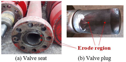
During the well control of high yield high-pressure oil/gas wells, throttle valve works under very harsh conditions, namely, large flow and high working pressure. The fluid medium is featured by strong corrosion, low viscosity, strong vaporability, high pressure, and high content of hard solid particles. As a result, the throttle valve faces cavitation, erosion, and corrosion damages. Among them, erosion is the main form of throttle valve failure during normal operations. The typical failure mode is shown in Figure 1.
The novel erosion resistance device can alleviate the erosion effect of the fluid medium on the outlet wall of the throttle valve, after being connected to the valve outlet. The previous literature has merely analyzed the flow field of the throttle valve. There is no independent research that tackles erosion resistance device. Using the three-dimensional (3D) flow field analysis software of computational fluid dynamics (CFD), this paper numerically simulates the flow field of erosion resistance device, and provides a theoretical reference for the field application of the device.
Figure 1. Typical failure mode of throttle valve
Repeated field surveys show that over 90% of throttle valves suffer from wedge surface erosion. The reason is that the high pressure of the throttle valve drives the fluid, which is mixed with various substances, to flow fast through the choke manifold. When the fluid passes through the throttle valve, the flow velocity further increases, as the flow area suddenly shrinks.
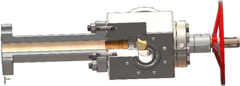
This paper numerically simulates the well control throttle valve currently used in Tarim Oilfield. The structure of the well control throttle valve is shown in Figure 2. In the current choke manifold, the original needle plug has been replaced with the wedge plug (Figure 2) to prevent the fatigue fracturing of the well control throttle valve. The cantilever beam structure with one fixed end has been changed into a simply supported beam with one fixed end and one supported end, thereby enhancing the fatigue resistance of the valve plug under unidirectional impact.
Figure 2. Structure of well control throttle valve adopted in Tarim Oilfield
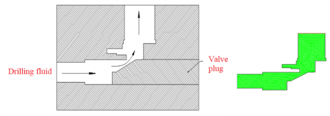
In practice, mud flow in wedge throttle valve is a 3D unsteady flow, obeying a very complex motion law. To quantify the flow trend and state of the fluid in throttle valve, this paper simplifies the symmetric plane of the valve as a plane flow for fluid analysis (Figure 3).
Figure 3. Structure model of mud flow state and finite-element model of fluid domain
The boundary conditions were configured as follows:
(1) Inlet boundary condition
The inlet velocity is 3m/s. The inlet turbulence parameters include inlet turbulent kinetic energy k and turbulent dissipation rate ε.
(2) Outlet boundary condition
The outlet adopts the fully-developed boundary condition, that is, the diffusion flux of all variables is assumed to be zero.
(3) Wall boundary condition
The wall adopts a non-slip boundary condition. The standard wall function is applied to the near-wall region.
(4) The throttle valve is subject to mapped meshing. To ensure solution accuracy, the grid density is appropriately increased in places with a large fluid gradient, e.g., the wall (Figure 2). The fluid density is 1,800 kg/m3, and the dynamic viscosity is 0.02 Pa∙s [18, 19].
The mud flow inside the throttle valve is a very complex turbulent flow. For simplicity, the fluid flow in the erosion resistance device was derived from the closed equation of the standard k-ε equation model [20].
The continuity equation can be expressed as:
$\frac{\partial \rho }{\partial t}+\frac{\partial \left( \rho {{u}_{i}} \right)}{\rho {{x}_{i}}}=0$ (1)
The conservation of momentum equation can be expressed as:
$\begin{align} & \frac{\partial \left( \rho {{u}_{i}} \right)}{\partial t}+\frac{\partial \left( \rho {{u}_{i}}{{u}_{j}} \right)}{\partial {{x}_{i}}}= \\ & -\frac{\partial p}{\partial {{x}_{i}}}+\frac{\partial }{\partial {{x}_{i}}}\left( \eta \frac{\partial {{u}_{i}}}{\partial {{x}_{j}}}-\rho u_{i}^{\prime }u_{j}^{\prime } \right) \\ \end{align}$ (2)
The turbulence model can be expressed as:
$\begin{align} & \rho \frac{\partial \varepsilon }{\partial t}+\rho uk\frac{\partial \varepsilon }{\partial xk}=\frac{\partial \varepsilon }{\partial xk}\left[ \left( \eta +\frac{{{\eta }_{t}}}{{{\sigma }_{t}}} \right)\frac{\partial \varepsilon }{\partial xk} \right] \\ & +\frac{{{c}_{1}}\varepsilon }{k}\eta +\frac{\partial {{u}_{i}}}{\partial {{x}_{j}}}\left( \frac{\partial {{u}_{i}}}{\partial {{x}_{j}}}+\frac{\partial {{u}_{i}}}{\partial {{x}_{i}}} \right)-{{c}_{2}}\rho \frac{{{\varepsilon }^{2}}}{k}\rho \frac{\partial k}{\partial t} \\ & +\rho {{u}_{j}}\frac{\partial k}{\partial {{x}_{i}}}=\frac{\partial }{\partial {{x}_{i}}}\left[ \left( \eta +\frac{{{\eta }_{t}}}{{{\sigma }_{k}}} \right)\frac{\partial k}{\partial {{x}_{j}}} \right]+{{\eta }_{t}}\frac{\partial {{u}_{i}}}{\partial {{x}_{j}}} \\ & +\left( \frac{\partial {{u}_{i}}}{\partial {{x}_{j}}}+\frac{\partial {{u}_{i}}}{\partial {{x}_{i}}} \right)-\rho \varepsilon \\ \end{align}$ (3)
${{\eta }_{t}}={{c}_{u}}\rho {{k}^{2}}/\varepsilon $ (4)
where, ρ is fluid density, kg/m3; P is pressure, Pa; μ is fluid velocity vector, m/s; ηt is turbulent viscosity, kg/(m∙s); ε is dissipation rate, m2/s3; k is turbulent kinetic energy, m2/s2; Cμ=0.09, C1=1.14, C2=1.92, σ1=1, and σ2=1.3 are constants.
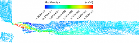
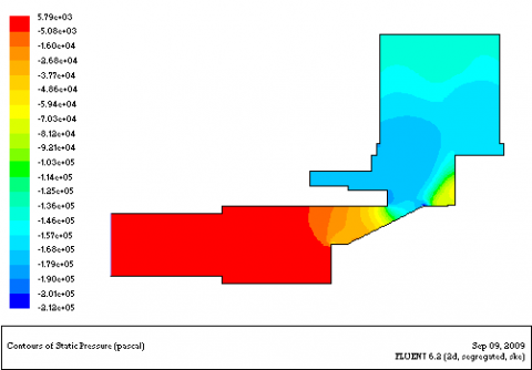
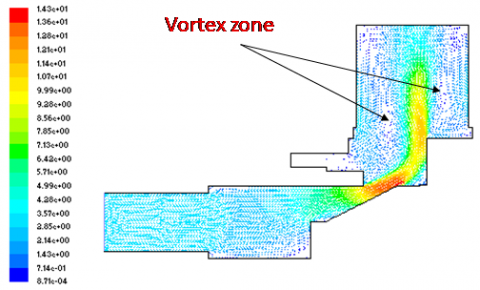
In the entrance section of choke manifold, drilling fluid erodes the manifold wall with a high axial velocity. After colliding into the wall, the fluid changes direction, and results in backflow and hedging. Then, two local vortex regions appear in the choke manifold, which accelerates the erosion and wear of the wall in these regions (Figure 4). From the pressure contour of the throttle valve, it can be observed that the stress was relatively great on the front surface of the valve plug (Figure 4(b)). The excessive stress could easily cause plug failure.
Figure 5 presents the cloud maps of the velocity contour and vortex zone in the throttle valve. It can be learned that the velocity vector peaked along the axial direction of the wedge surface of the throttle valve. Because of the various granular substances in the mud, the fluid picks up speed after passing through the orifice, and the resulting high-speed fluid will scour the wedge surface. The cutting effect will be very prominent on the opposite side. Under the high pressure and high flow rate, the wedge surface will be easily damaged, and the throttle orifice will fail. One of the main reasons for the erosion is that the planar wedge surface creates a huge resistance to the passing fluid. The opening of the valve also has a great impact on fluid flow.
(a) Velocity distribution of drilling fluid
(b) Pressure contour
Figure 4. Drilling fluid velocity and direction in horizontal plane and pressure contour
(a) Velocity contour
(b) Vortex zone
Figure 5. Velocity contour and vortex zone in throttle valve
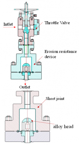
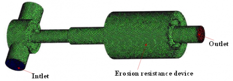
Figure 6. Installation position of erosion resistance device and profile of alloy head
To reduce the erosion failure of throttle valves, this paper designs an erosion resistance device. Figure 6 shows the installation position of the proposed device. The erosion resistance device mainly consists of main body, flange, valve seat nipple, and alloy head. The valve, seat, seat bush, nipple bush, and nipple head are all made of hard alloy materials. The drilling fluid passes through the throttle valve to reach an abrupt cavity via the nipple, and changes direction as it flows through the hemispherical cover of the alloy head. Finally, the fluid gathers in the pores of the outer cylindrical surface of the alloy head, and flows to the outside. The erosion resistance device mainly consumes the energy acting on downstream components, and increases the resistance to fluid flow.
4.1 Assumptions
In the throttle valve, the flow field in the erosion resistance device is a complicated flow in fluid machinery. Despite being a viscous, incompressible 3D unsteady flow, the flow field satisfies the conservation equations of mass, momentum, and energy [21]. According to the features of throttle valve, the following assumptions were made [22]:
(1) Gravity has no effect on the fluid;
(2) The flow system is adiabatic, i.e., does not exchange heat with the outside. The energy equation needs no consideration;
(3) The mud flow field has a negligible impact, and the mud flow is a single-phase flow.
4.2 Meshing model
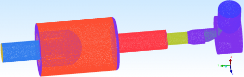
The computational domain of the anti-erosion choke manifold is much more complex than that of the original choke manifold, making it difficult to mesh the domain into structured grids. Therefore, non-structured grids were adopted for meshing, and adaptive grids were employed to improve calculation accuracy. The plug of the throttle valve was meshed into denser grids; the grids of the anti-erosion nipple were refined as a radiation network, with the highest density at the center. As shown in Figure 7, the finite-element model contains 765,015 nodes, and 3,210,541 grids, including 2,652,329 tetrahedral grids, 2,750 conical grids, and 462,241 wedge grids.
Figure 7. Finite-element model of the computational domain
The meshing quality directly bears on the accuracy of flow field simulation. From computing efficiency, accuracy, and meshing difficulty, this paper adopts unstructured grids and grids with mixed and tetrahedral elements to refine the inlet grids, outlet grids, and wedge surface grids. Figure 8 shows the meshing results.
Figure 8. Finite-element model of erosion resistance device and inlet and outlet grids
4.3 Boundary conditions
Mass flow was taken as the inlet boundary: inlet mass flow=36Kg/s, ρ=1800kg/m3, and u=0.02Pa∙s [23]. Pressure was taken as the outlet boundary: outlet back pressure=0Pa. Non-slip condition was adopted for the wall, and the standard wall function was selected for the near-wall region. Studies have shown that re-normalization group (RNG)-based k-ε model with fixed compression is more realistic than the k-ε model [24]. Therefore, the RNG and k-ε equation were adopted for our turbulence model.
To objectively descript the fluid erosion effect on the erosion resistance device, the simulation results were analyzed under changing velocity and pressure.
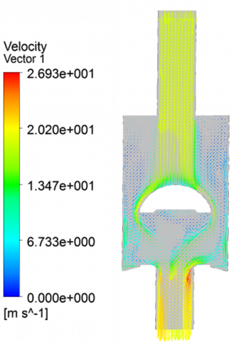
Figure 9. Velocity flow contour of erosion resistance device
Figure 9 presents the cloud maps of the velocity flow on the plane of the symmetric profile of the erosion resistance device. On the velocity flow map, there was an obvious vortex in the device, where the flow area is relatively large. The streamlines were very complex. The high-speed fluid mainly concentrated at the inlet and outlet, where the flow does not change greatly. The maximum velocity of the flow field was 26.93m/s. The results show that, after the fluid enters the erosion resistance device, the velocity first decreases and then increases at the outlet. The CFD analysis suggests that the mean velocities at the inlet and outlet were 20.75m/s and 18.26m/s, respectively. Moreover, vortex is generated, the incoming flow velocity at the left of the short joint is large, and the flow is relatively concentrated.
Figure 10. Partial enlarged view and Four selected paths
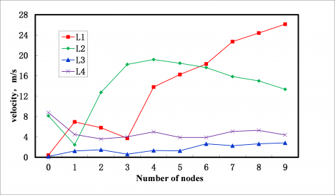
Figure 11. Velocity distribution on the four paths
In order to further analyze and select the velocity profile of the fluid in the short section as the object, it can be seen from Figure 10 that the wall surfaces on the left and right sides are arranged symmetrically. Here, the axial center line velocity of the outlet channel is selected as a vertical line L1, the alloy head is short connected with a vertical line L2 on the middle left wall surface and a arc L3 on the arc surface to study the change of the velocity, A vertical line L4 on the axial center line of outlet channel is selected to find out the law of the erosion action of fluid velocity on the short section and valve body.
It can be seen from Figure 11 that the velocity value in the velocity line L1 increases and then decreases, and then the velocity of the fluid in L1 near the top of the alloy head gradually increases to the maximum. From the velocity vector diagram, it is found that the maximum impact velocity occurs at the top of the arc surface of the alloy head. Because the cross-sectional area of the erosion resistance device inlet end changes from small to large. And the cross-sectional area of the outlet end is the same as that of the inlet end when the fluid finally flows out. L1 and L4 can be seen that when the fluid enters the inlet and outlet end, the velocity on L1 is obviously higher than that of L4, and finally tends to be equal. Because the overflow area in the middle of the short joint is the largest, its velocity value is smaller than that on the velocity lines L2 and L4. According to the erosion mechanism, from L1, L2 According to the velocity diagram of L4, when the flow is constant, the smaller the overflow area is, the greater the velocity is, which is consistent with the hydrodynamic control equation. From the velocity curve data L3 on the alloy head, it is found that the velocity changes little and tends to be horizontal, and the surface velocity of the alloy head is relatively flat.
As can be seen from the figure, this shows that after adding stab proof nipple, the fluid velocity on the wall can be effectively reduced, so as to reduce the erosion to the wall.
1) Using the three-dimensional flow field analysis software of computational fluid dynamics (CFD), it is found that the velocity on the left wall is greater than that on the right. The field failure investigation also proved that the erosion damage mainly occurred on the left wall of the throttle valve, which verified the failure causes of the throttle valve core and valve seat.
2) From the velocity vector diagram, it can be seen that there is obvious eddy current in the fluid inside the short section, and it shows turbulence state. The high-speed fluid mainly concentrates on the small change of the flow area between the outlet end and the inlet end. The maximum pressure occurs at the arc position at the top of the erosion resistance device body, and the maximum velocity of the flow field is 26.93m/s, after the fluid enters the short connection of stab prevention, It can be seen from the exit end of the short stabbing section that the velocity changes from large and then from small to large. The results of CFD analysis show that the average velocity of inlet is 20.75m/s, the average exit velocity is 18.26m/s, and there is eddy current. The flow velocity at the left of the short joint is larger and the flow ratio is relatively concentrated.
3) In addition, the flow field of the erosion resistance device is numerically simulated. The results show that under the given boundary conditions, when the fluid passes through the inlet and outlet of the erosion resistance device, the average velocity changes little. It is known from the velocity curve that under a certain flow rate, the smaller the overflow area is, the greater the velocity is, which is consistent with the hydrodynamic control equation. From the velocity curve data on the alloy head, it is found that the velocity changes little and tends to be horizontal, and the surface velocity of the alloy head is relatively flat, which shows that the fluid velocity on the wall can be effectively reduced after adding the stab prevention short section, so as to reduce the erosion on the wall.
[1] Zhang, X.L. (2007). Study on features of fixed throttle valve. Natural Gas Industry, 27(5): 63-65. https://doi.org/10.3321/j.issn:1000-0976.2007.05.019
[2] Zhou, J.Z., Lian, Z.H., Wang, Y.H., Liu, Y., Wu, J. (2019). Failure analysis and structure optimization of throttle valve core. China Petroleum Machinery, 47(12): 131-138. https://doi.org/10.16082/j.cnki.issn.1001-4578.2019.12.020
[3] Wang, D.G., Li, Y.F., Yan, J.L., Fang, Q. (2012). The influence of the erosion resistance device to the throttle valve’s flow characteristics. Valve, 2012(1): 8-10. https://doi.org/10.16630/j.cnki.1002-5855.2012.01.005
[4] Cao, Y., Fang, X.Q., Zhang, J.L., Tang, D.X. (2020). Experimental evaluation on the anti-erosion performance of throttle valves for drilling. Natural Gas Industry, 40(5): 89-94. https://doi.org/10.3787/j.issn.1000-0976.2020.05.011
[5] Tu, Y.D., Xu, X.B., Yin, H.F., Du, J., Chen, F.Y., Qiu, J. (2018). Analysis on erosion wear laws of high pressure manifold. China Petroleum Machinery, 46(2): 84-88. https://doi.org/10.16082/j.cnki.issn.1001-4578.2018.02.015
[6] Song, B.J., Ming, X., Sun, K., Lan, K. (2018). Study on the erosion law of wedge-shaped throttle valve. Oil Field Equipment, 47(4): 30-34. https://doi.org/10.3969/j.issn.1001-3482.2018.04.006
[7] Fu, Y.K., Liu, Q.Y., Wang, G.R., Tao, S.Y. (2013). Mathematical modeling and validation on a new valve core of the throttle valve in MPD. Advances in Mechanical Engineering, 5: 125936. https://doi.org/10.1155/2013/125936
[8] Xu, E., Nie, C., Jiang, X., Miao, Z. (2021). Theoretical investigation on the throttle pressure reducing valve through CFD simulation and validating experiments. Korean Journal of Chemical Engineering, 38(2): 400-405. https://doi.org/10.1007/s11814-020-0703-2
[9] Xu, E., Chen, Y., Miao, Z., Jiang, X., Zhang, Y., Xie, L. (2021). A novel structure of throttle trap valve for self-adjustment of discharge capacity in high pressure heat exchangers. Progress in Nuclear Energy, 135: 103719. https://doi.org/10.1016/j.pnucene.2021.103719
[10] Sang, Y., Wang, X., Sun, W. (2019). Analysis of fluid flow through a bidirectional cone throttle valve using computational fluid dynamics. Australian Journal of Mechanical Engineering, 19(1): 71-80. https://doi.org/10.1080/14484846.2019.1578042
[11] Self, R.H. (2004). Jet noise prediction using the Lighthill acoustic analogy. Journal of Sound and Vibration, 275(3-5): 757-768. https://doi.org/10.1016/j.jsv.2003.06.020
[12] Berestovitskiy, E.G., Ermilov, M.A., Kizilov, P.I., Kryuchkov, A.N. (2015). Research of an influence of throttle element perforation on hydrodynamic noise in control valves of hydraulic systems. Procedia Engineering, 106: 284-295. https://doi.org/10.1016/j.proeng.2015.06.037
[13] Chen, X., McLaury, B.S., Shirazi, S.A. (2004). Application and experimental validation of a computational fluid dynamics (CFD)-based erosion prediction model in elbows and plugged tees. Computers & Fluids, 33(10): 1251-1272. https://doi.org/10.1016/j.compfluid.2004.02.003
[14] Lopez, D., Congote, J.P., Cano, J.R., Toro, A., Tschiptschin, A.P. (2005). Effect of particle velocity and impact angle on the corrosion–erosion of AISI 304 and AISI 420 stainless steels. Wear, 259(1-6): 118-124. https://doi.org/10.1016/j.wear.2005.02.032
[15] Lian, Z.H., Liu, G., Gong, J.W., Yi, H., Liu, Y.Y., Zhang, X.L. (2004). Fluid field analysis of high pressure throttle valve and its structure improvement. China Petroleum Machinery, 32(9): 22-24. https://doi.org/10.3969/j.issn.1001-4578.2004.09.008
[16] Tao, W.Q. (2001). Numerical Heat Transfer. Xi'an: Xi'an Jiaotong University Press.
[17] Nie, S.L., Huang, G.H., Li, Y.P. (2006). Tribological study on hydrostatic slipper bearing with annular orifice damper for water hydraulic axial piston motor. Tribology International, 39(11): 1342-1354.
[18] Yang, G.L., Yang, C.A., Liu, Z.G., Ma, Y.C. (2009). Simulation research on flow field characteristics at small opening of throttle valve and relation to minimal steady flow rate. Machine Tool & Hydraulics, 37(9): 109-111. https://doi.org/10.3969/j.issn.1001-3881.2009.09.037
[19] Zhang, D.S., Zhao, J.Y., Liu, L.B., Lu, W.C. (2010). Flow field analysis and structure optimization of peach shaped chamber hydrodynamic coupling based on CFD. Journal of China University of Mining & Technology, 39(5): 687-692.
[20] Liu, G. (2003). Research on throttle valve structure and its flow field numerical simulation analysis. Southwest Petroleum University. 2003.
[21] Stack, M.M., Abdelrahman, S.M. (2011). A CFD model of particle concentration effects on erosion–corrosion of Fe in aqueous conditions. Wear, 273(1): 38-42. https://doi.org/10.1016/j.wear.2011.06.024
[22] Nie, S.L., Huang, G.H., Li, Y.P. (2006). Tribological study on hydrostatic slipper bearing with annular orifice damper for water hydraulic axial piston motor. Tribology International, 39(11): 1342-1354. https://doi.org/10.1016/j.triboint.2005.10.007
[23] Bai, L., Mitra, N.K., Fiebig, M. (1995). Computation of unsteady 3D turbulent flow and torque transmission in fluid couplings. In Fourteenth International Conference on Numerical Methods in Fluid Dynamics, 435-440. https://doi.org/10.1007/3-540-59280-6_163
[24] Zhang, D.S., Zhao, J.Y., Liu, L.B., Lu, W.C. (2010). Flow field analysis and structure optimization of peach shaped chamber hydrodynamic coupling based on CFD. Journal of China University of Mining & Technology, 5.