Bholu Kumar | Suresh Kant Verma | Shantanu Srivastava*
© 2021 IIETA. This article is published by IIETA and is licensed under the CC BY 4.0 license (http://creativecommons.org/licenses/by/4.0/).
OPEN ACCESS
The present study focuses on the effect of nozzle exit inclination on the mixing characteristics of Mach 2.17 overexpanded jets at the NPR 5, NPR 6 and NPR 7, using commercial software package ANSYS Fluent. The convergent-divergent nozzles, investigated are circular nozzle and bevel nozzle with bevel angle 300, and bevel angel 450. The nozzles are constructed with equal throat-to-exit area ratio, in order to maintain uniform Mach number at the nozzle exit. From the results, it was found that, the bevelled nozzles effectively reduce the jet core as much as 46%, indicating enhanced jet mixing. It was also observed that at lower NPR, i.e., at NPR 5, the Bevel30 nozzle is found superior over Bevel45 and circular nozzle and at the intermediate NPR, both of the Bevel30 and Bevel45 nozzle reduces the jet core with the same rate. However, at highest NPR of the present study, the Bevel45 nozzle exhibits the highest mixing enhancement. An early axis switching is seen for the Bevel30 jet at NPR 5 and for the Bevel45 jet at NPR 7.
jet mixing, supersonic, bevel nozzle, k-ω SST, fluent
The study of supersonic jet from axisymmetric convergent-divergent nozzles has been done by many researchers in the recent past [1-5]. However, modifying the nozzle geometry by the introduction of azimuthal asymmetry is well established method of controlling the mixing and noise characteristics of a typical supersonic jet. The jet from Bevel nozzle has its mixing characteristics modified due to the prevailing azimuthal asymmetry. The study of jets from beveled nozzles was first reported by Wlezien and Kibens [6]. The work involved investigation of flow field and noise-generation characteristics of jets from non-axisymmetric nozzles at supersonic pressure ratios. However, constant diameter tubes were used as non-axisymmetric nozzles, it was found that, the jet deflects from the axis of the nozzle. Further, one of the significant findings is that, these jets likely exhibit increased mixing because of the augmented shear-layer surface area. The experimental investigation on mixing and noise characteristics of the rectangular bevelled nozzles was conducted by Rice and Raman [7]. The results were presented as Mach contours and noise spectra for a series of nozzles. It was reported that, the bevelled nozzle exits shifts the mixing noise peak to higher frequency. The spark schlieren photographs taken by Raman [8] showed that, the flow from the bevelled nozzle does not diverge significantly in the spanwise direction. Tam et al. [9] in their work on bevelled rectangular nozzles showed that, the shock cell structures can be decomposed into waveguide modes of the jet flow. Vishwanathan [10] studied bevelled nozzles in terms of the aero-acoustics capabilities and showed that the manipulating the noise caused by large-scale structures resulted in overall noise reduction. The experimental investigation on turbulent, low-speed air jets issuing from bevelled circular collared-nozzle was conducted by Zeng et al. [11]. However, the jets studied were subsonic, the study reported that the increase in bevel angel causes rapid decay of jet centreline velocity, which is an indirect method for manifestation of enhanced jet mixing. An experimental investigation along with numerical simulation on supersonic jets from bevelled nozzles was reported by Wu and New [12]. The results of the study showed that, the pattern of the shock cell structure within the jet potential of the jet from bevelled nozzle transformed from diamond structure to triangular and rectangular, with the changes in NPR (nozzle pressure ratio) and inclination angle. The significant finding of this study showed that, bevelled nozzles lead to shorter jet potential core lengths along the nozzle centerline. The mean and variance of velocity predictions for the jet from bevelled rectangular nozzles were made by Sandya and Tide [13]. It was found that, the beveled nozzle is capable of improving jet mixing and other turbulence parameters of the flow. Wu et al. [14] introduced circular collar at the exit of a circular Mach 1.46 nozzle and made the double bevel cut of 30° and 60° at the collar exit, and, compared the results with non-beveled collar nozzle. The test NPR were varied between 2.8 to 5. They found that, the 60° double beveled nozzle shown higher near-field shock reduction when compared to the 30° double beveled nozzle and non-beveled nozzle. Furthermore, with reducing NPR along the TT plane (trough to trough plane), the enhance jet spread was reported. However, along PP plane (peak to peak plane) the jet spread highly suppressed in under-expansion condition. The asymmetric shock structures and instability waves produced by bevelled nozzles are found beneficial for the jet screech elimination [15]. It is also important to note that all bevelled nozzle does not significantly reduce the jet screech with non-optimum design condition.
Gutmark and Ho [16], Ho and Gutmark [17], Quinn [18], Hussain, F. and Husain, H.S. [19], Husain H.S. and Hussain, F. [20, 21] and Lee and Baek [22] studied evolution of jet cross-section from elliptical nozzles. Thus, it cannot be over emphasized that, the mixing characteristics of the bevelled nozzles is attributed to the behavior of vortical structures at the nozzle exit. The pertinence of such vortical structures were studied by New and Tsovolos [23]. It was found that, inclination angles cause substantial effects on the vortex-dynamics of the jets. The major-plane inclined elliptic nozzles have lower vortex strength. It was also reported that, bevelled nozzles have potential capability of suppressing axis-switching in elliptic jets.
It is well-established from the literature that, most of the work on the jets from bevelled nozzles, focused on the investigation of acoustic characteristics. Also, it is clear from the literature that, the bevelled nozzles considered in the recent studies were either used as bevelled collar [12, 14, 15, 24] or nozzles with elliptical cross-section. The present work involves computational study of the effect of nozzle exit inclination on the mixing characteristics of Mach 2.17 jet in the over-expanded conditions. The nozzle considered for the present study is of circular cross-section from inlet to exit, with elliptical nozzle exit cross-section. The nozzle pressure ratio (NPR) for the present work ranges from 5 to 7 in step sizes of one. The nozzles considered for this work consists of circular nozzle (Zero inclination at exit), Bevel nozzle with a bevel angle of 30° (Bevel30 nozzle) and Bevel nozzle with a bevel angle of 45° (Bevel45 nozzle). The RANS equations comprising of mean and fluctuating components are solved in the commercial software package ANSYS Fluent. The turbulence modelling of the turbulent parameters is evaluated using SST k-ω turbulence model.
The mixing enhancement of Supersonic Mach 2.17 over-expanded jet issuing from three types of convergent-divergent (CD) nozzle, namely, (i) Circular nozzle, (ii) Bevel30 nozzle, and (iii) Bevel45 nozzle have been investigated using commercial software package ANSYS Fluent. The construction of these nozzles for Mach 2.17 jet has been done using Area-Mach number relation [25], and the computational models are generated in ANSYS Design modeler of version 17.2 for equal exit-to-throat area ratio of the nozzle to produce Mach 2.17 jet at the nozzle exit. The three-dimensional unstructured meshing is achieved through ICEM, and the flow analysis through solution of governing equations has been carried out using ANSYS Fluent of version 19.2.
2.1 Computational models
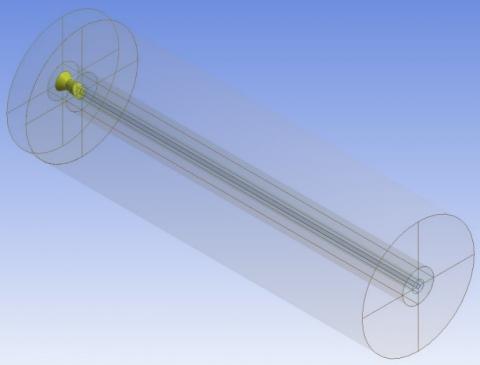
The convergent-divergent circular, Bevel30, and Bevel45 nozzles are constructed using ANSYS design modeler, Figure 1. The convergent and divergent angle of each nozzle is fixed at 30° and 7°, respectively with variation in the respective lengths of the nozzles, in order to maintain the same designed Mach number. The throat diameter of each of the nozzles is fixed to 13 mm and exit equivalent diameter of each of the nozzles is maintained at 18.15 mm, so that to get same Mach number at the nozzle exit. The domain chosen is cylindrical, which encloses each of the nozzles for analysis; as shown in Figure 2. The computational domain is extended to about 30D and 5D, respectively, along the axial and radial directions, from the nozzle exit; where D (= 18.15 mm) is the equivalent diameter of the nozzle exit. A cartoon of the jet issuing from the nozzle exit, showing the direction of jet flow is shown in Figure 3.
Figure 1. Three-dimensional CD Nozzles constructed in ANSYS design modeler
Figure 2. Three-dimensional CD Bevel Nozzle enclosed by cylindrical domain
Figure 3. Nozzles and the direction of jet centerline
2.2 Mesh generation
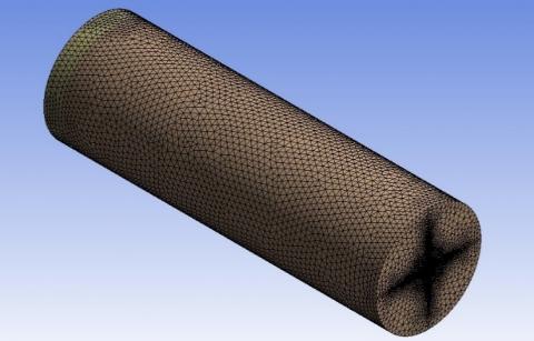
The three-dimensional tetrahedron grids are generated for each of the models, as shown in the Figure 4. The suitable edge sizing and refinement of the grids has been done, so as to calculate precisely, the flow parameters involved in the jet issuing from the nozzles. The grids in the near-field are comparatively more refined as the presence of axis-switching behavior in the near-field is prominent due to the prevailing vortex dynamics. Furthermore, in order to adopt suitable grids size for each of the computational model, gird independence test (GIT) is conducted which tells at what grids size the results become independent of it; discussed in section 2.2.1.
Figure 4. Typical computational grids
2.2.1 Grid independence test
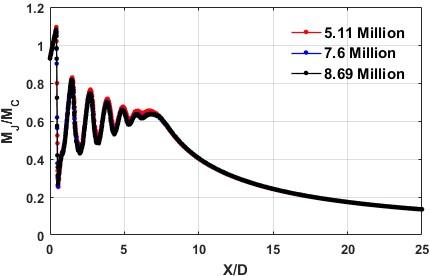
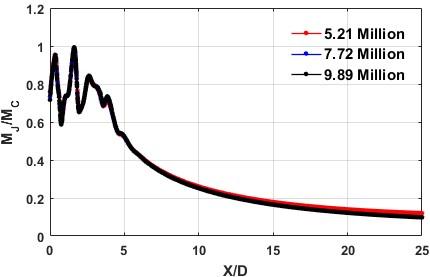
Each of the test cases are simulated for at least three different numbers of grid sizes to check the independence of result with the grid size, as shown in Figure 5. The axial distance (X) along the jet centerline is made non-dimensional by dividing with the equivalent diameter of the nozzle exit (D), and the variation Mach number with the axial distance is presented.
It was found that, the circular nozzle, and each bevel nozzles included in the flow domain were independent of girds at and above 7.60 million, 7.72 million, and 7.95 million cells, respectively, which are clearly seen from Figure 5 (a), Figure 5 (b) and Figure 5 (c) respectively. Thus, the grid size of 7.60 million, 7.72 million, and 7.95 million are respectively adopted for the computational simulations of the jets from circular, Bevel30, and Bevel45 nozzles.
(a) GIT for the jet issuing from the circular nozzles
(b) GIT for the jet issuing from the Bevel30 nozzle
(c) GIT for the jet issuing from the Bevel45 nozzle
Figure 5. Grid independence test
The meshing properties of each of the computational domains is given in Table 1. A higher skewness was anticipated due to the interfacing between the nozzle and the cylindrical domain. However, out of millions of grids, only few grids show the higher value of skewness, and these grids are also found out from the region of the intense mixing layer and thus do not cause the problem in the convergence of the solutions. Out of 7.60 million elements of the circular nozzle computational domain, only 117 elements show the maximum skewness 0.86. Similarly, the maximum skewness of about 0.88 and 0.91 are reported respectively for Bevel30 and Bevel45 nozzles, where only 49 and 68 elements show this maximum skewness value, respectively for Bevel30 and Bevel45 nozzles. These minor elements of higher skewness value do not affect the convergence of the solution, as mentioned earlier.
Table 1. Meshing properties of computational models
|
Properties |
Circular nozzle |
Bevel30 nozzle |
Bevel45 nozzle |
|
No. of Grids (in Millions) |
7.60 |
7.72 |
7.95 |
|
Max. A.R. |
10.67 |
13.50 |
16.74 |
|
Max. Skewness |
0.86 |
0.88 |
0.91 |
|
Max. Orthogonality |
0.99 |
0.99 |
0.99 |
The Numerical solution of the problem is based on the finite volume methods. Each control volume (grid) of the respective computational domain is discretized using governing and subsidiary equations of the fluid flow, converted into the algebraic form. The numerical methods are then applied to get the final results as centerline pressured decay plots, pressure profiles and numerical shadowgraph images. The governing equations are given as follows.
3.1 Governing equations
The governing equations of jet flow applied here include the conservation form of Navier-Stokes system (CNS), which expresses the conservation of mass, momentum, and energy.
$\frac{\partial u}{\partial x}+\frac{\partial v}{\partial y}+\frac{\partial w}{\partial z}=0$ (1)
$\rho \frac{\partial\left(U_{i} U_{j}\right)}{\partial x_{j}}=-\frac{\partial P}{\partial x_{i}}+\frac{\partial}{\partial x_{i}}\left[\mu\left(\frac{\partial U_{i}}{\partial x_{j}}+\frac{\partial U_{j}}{\partial x_{i}}\right)-\rho \overline{U_{i} U_{j}}\right]$ (2)
The above system of equations is converted into Reynolds Averaged Navier-Stokes system of equations, by splitting the pressure and velocity terms into mean and fluctuating components. These governing differential equations are then discretized to obtain the simultaneous sets of the algebraic equation for each cell. Thereafter, numerical methods such as Gauss-Seidel, Runge-Kutta, etc., methods are applied for the further treatment of algebraic equations to get the solution.
3.2 Turbulence model
The SST k-ω turbulence model is used to solve the Reynolds-averaged Navier-Stocks equations. The SST k-ω turbulence model is frequently used [26-29] to simulate the supersonic jet due to its hybrid nature for capturing turbulence both near and far from the wall using both k-ε and k-ω turbulence model [30]. The k-ε turbulence model is used to capture the turbulence far from the wall; however, the k-ω turbulence model captures the turbulence near the wall. Thus, SST k-ω turbulence model captures the turbulence in both the scenario by using a function F1, which enables us to pass from the k-ω model near the wall to the k-ε model far away from it.
$\frac{\partial(k)}{\partial t}+<u_{j}>\frac{\partial k}{\partial x_{j}}$$=\frac{\partial}{\partial x_{j}}\left[\left(v+\frac{v_{t}}{\sigma_{k}}\right) \frac{\partial k}{\partial x_{j}}\right]-\beta^{*} k \omega_{k}$$+v_{t} S^{2}$ (3)
$\frac{\partial \omega}{\partial t}+<u_{j}>\frac{\partial \omega}{\partial x_{j}}=\frac{\partial}{\partial x_{j}}\left[\left(v+\frac{v_{t}}{\sigma_{\omega}}\right) \frac{\partial \omega}{\partial x_{j}}\right]-\gamma S^{2}$$-\beta f_{\beta} \omega^{2}+2 \sigma_{\omega 2}\left(1-F_{1}\right) \frac{1}{\omega}$ (4)
The coefficient ϕ is correlated with σk, ωk, γ, and β. The ϕ can be expressed as:
$\emptyset=F_{1} \emptyset_{1}+\left(1-F_{1}\right) \emptyset_{2}$ (5)
The coefficient ϕ1 and ϕ2 are enabled to capture the turbulence phenomena for the k-ω model (near the wall) and k-ε model (far from the wall) respectively. The function F1 assumes the value of 1 within the boundary layer and 0 outside the boundary layer. Further, to limit the turbulent viscosity in the region of adverse pressure gradient, Bradshaw [31] proposed the following hypothesis:
$v_{t}=\frac{a_{1} k}{\max \left(a_{1} \omega ; F_{2} \bar{\Omega}\right)}$ (6)
$\bar{\Omega}=\sqrt{2 \Omega: \Omega} \quad$ avec
$\Omega_{i j}=\frac{1}{2}\left(\frac{\partial<u_{i}>}{\partial x_{j}}-\frac{\partial<u_{j}>}{\partial x_{i}}\right)$ (7)
where, a1 is the Bradshaw constant, which assumes the value of 0.31. The Bradshaw correlation uses F1 = 1 in the boundary layer and F2 = 0 (vt = k/ω) outside of the boundary layer.
3.3 Boundary conditions
The inlet (boundary A1) of each nozzle is specified by pressure inlet boundary condition (refer Figure 3). The far-field of the computational domain (A4, A5, A6, and A7) is also specified by pressure inlet boundary condition. The wall boundary condition is set for the nozzle wall (A2 and A3), and the pressure outlet boundary condition is used for outlet A8.
3.4 Numerical simulation
The numerical simulation on the modelled fluid has been carried out using the Fluent solver of ANSYS 19.1 workbench. As air is compressible, the pressure-based solver is applied. The pressure-velocity coupling with pseudo transient is enabled in the Fluent solver. The above settings give the same result as that with the density-based solver and also provides faster convergence of the solutions. Second-order and second-order upwind schemes, respectively, discretize the pressure and convective terms. In order to get a smooth solution and fast convergence, the full multigrid initialization is set respectively for four multigrid levels 2500, 5000, 10000, and 20000 with the convergence criteria of 1e-03 and the courant number of 0.25.
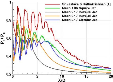
The lack of experimental and numerical evidence for the mixing characteristics of Mach 2.17 jet from convergent-divergent bevelled nozzle of circular cross-section with elliptical exit, compels the computational validation of the present study with the mixing characteristics of Mach 1.86 jet, discharged from a convergent-divergent nozzle of square cross-section from inlet to exit. The computational results of centerline pressure decay of the Mach 1.86 jet from square nozzle, Mach 2.17 jet from Bevel30 nozzle, Mach 2.17 jet from Bevel45 nozzle, Mach 2.17 jet from circular nozzle and experimental results of Srivastava and Rathakrishnan [1] are compared and shown in Figure 6. It is observed that the computational results of Mach 1.86 square jet show almost the same number of shock-cells and exhibit the same nature of flow pattern as that of experimental result. Both the results differ only in the pressure levels. The lower pressure level of Mach 1.86 square jet in the computational result is justifiable due to additional shocks-cells introduced by the pitot probe during experimentation. In the experimental centerline pressure decay measurement, the tip of the pitot probe was placed normal to the flow and due to the interference of the pitot probe oblique shocks are generated ahead of the pitot probe in addition to naturally occurring shocks due to cumulative effect of sudden pressure change and large space at the nozzle exit.
In computational investigations, the pressure measurements can be made right from the nozzle exit. This enables to capture the shocks occurring at the nozzle exit, as a result of combined effect of the sudden pressure change and large relaxation space offered to the jet, at the exit of the nozzle. The pressure levels measured by the experimental study on the jet from Mach 1.86 square nozzle is higher than that for the computational results. This aberration is due to the difference between a real experimental set-up in laboratory and an ideal experiment on a computer. The circular jet, Bevel30 jet, and Bevel45 jet repeat the same flow pattern with pressure levels falling below the experimental result, and slight variation in the number of shock-cells and strength of shock would occur due to the different nozzle exit cross-sections (Bevel30 and Bevel45) and different Mach number, i.e., Mach 2.17. Thus, it can be inferred that, the computational scheme (SST k-ω) adopted in the present study will reap acceptable and satisfactory results.
Figure 6. Computational validation of present investigation with experimental results of Srivastava and Rathakrishnan at NPR 5
The supersonic flows are highly wave-dominated, and any a change in state (p, ρ, T) or direction is brought about by waves. Due to this the study of supersonic jet becomes more complicated as compared to that of subsonic and sonic jets. The supersonic jet exhibits the well-defined typical flow zones such as potential core, characteristics decay, and fully developed zones. In the supersonic flow, the jet core is the region where the jet centerline velocity remains supersonic. The jet core is followed by the characteristic decay zone which is the intermediate zone between the supersonic flow and the self-similar profile of the jet. It has been established in the literature that, as the jet exits from the nozzle, vortical structures are generated in the shear layers sandwiched between the stagnant ambient and the jet boundary. These vortical structures play a significant role in the mixing of the jet with the ambient. However, the quantification of jet mixing has appeared to be an abstract concept in the literature because of its dependence on the proper proportion of large scale and small-scale vortices. The vortices generated due to the differential shear at the jet boundary are mostly large scale. The large-scale vortices engulf huge mass of the ambient fluid into the jet field however, they experience vortex-tearing very soon and get fragmented into small scale vortices, which are good transporters. The quantification of jet mixing can be done by indirect means which is the measurement of jet core length. The jet with shorter core demonstrates better jet mixing, compared to that with a longer core. The jet core length is indicated by the plot of centerline pressure decay, which is the variation of total pressure at the jet centerline with respect to the distance downstream of the nozzle exit.
5.1 Centerline velocity decay
The dependence jet velocity on the total pressure, has been established in the literature [25]. Furthermore, the supersonic jet is a turbulent flow-field which is highly wave dominated. Thus, any change in the flow properties or direction is brought about by the waves. It can be seen from the simple Gas-Dynamics relations that, the supersonic velocity along the jet centerline is a strong function of total pressure downstream of the nozzle exit, along the jet centerline. For investigating the influence of nozzle exit plane inclination on the jet mixing, the local Mach number of jet (MJ) along the jet centerline is non-dimensionalised by correctly expanded Mach number (MC) and plotted as the function of non-dimensional axial distance (X/D), where X/D = 0 is the nozzle exit.
The jet in the present study is over-expanded, which means that the static pressure at the exit of the nozzle is less than the ambient pressure, and due to this, an adverse pressure gradient exists at the nozzle exit. In order to achieve the equilibrium state, the flow is compressed from the pressure level of the nozzle exit to the ambient pressure through oblique shocks at the nozzle-lip. The significant role of the vortex dynamics effecting the jet mixing appears when nozzles of different exit plane inclinations are subjected to varying NPRs. The vortices shed by the different exit plane inclinations behave differently. This is because the vortex roll-up inclination gradually, change and evolve as they move downstream of the nozzle exit. It has been established that, as the exit inclination is increased beyond a certain threshold, the vortex turning takes place which effects the mixing characteristics and the tendency of axis-switching.
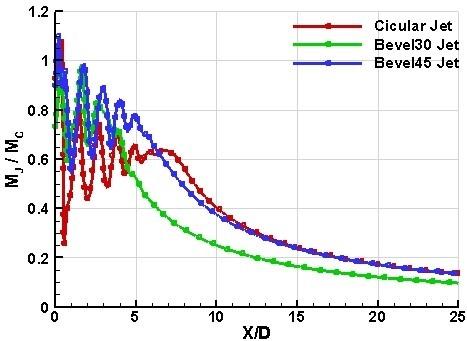
The centerline velocity decay of the jet from circular, Bevel30 and Bevel45 convergent-divergent nozzles at NPR 5 are shown in Figure 7. At NPR 5, the jets are highly overexpanded with an overexpansion level of about 51%. The adverse pressure gradient at the nozzle exit generates shocks of opposite families at the nozzle-lip. The shocks are generated as oblique shocks which cross each other at the cross-over point at some distance downstream of the nozzle exit. This causes momentarily acceleration of the flow up to some distance downstream of the nozzle exit. The patterns of the oblique shocks are different for each nozzle of the study. The pattern is almost symmetrical for the circular nozzle. However, the pattern of oblique shock is asymmetrical for the Bevel30 and Bevel45 nozzles. It is interesting to see that, the bevel nozzles (Bevel30 and Bevel45) have lesser number of shock-cells as compared to the circular nozzle. However, the centerline velocity of all the jets exhibits almost same tune in the near-field. The number of shock-cells for the jet from Bevel30 nozzle are less than that for Bevel45 nozzle. Also, the decay rate for the Bevel30 nozzle is more than that for the Bevel45 nozzle. This might be due to the gradual increase in the inclination of the vortex roll-up downstream of the nozzle exit from the Bevel30 nozzle, as compared to that for Bevel45 nozzle.
Thus, jet core length reduction, and consequently jet mixing, are more in case of jet from Bevel30 nozzle, as compared to the other jets under the present study. The core length for the jet from Bevel30 nozzle extends to about 3.5D, however, that for the jet from circular nozzle extends to about 6.5D, as shown in Figure 7. The core length of Bevel45 jet extends to about 5D at NPR 5. Hence, the core length reduction of about 46% and 23% are respectively obtained for Bevel30 and Bevel45 jets as compared to the circular jet. Thus, at NPR 5, Bevel30 nozzle shows the highest jet mixing enhancement. Beyond 12D, the circular and Bevel45 jet execute almost the same nature. However, beyond 15D, the jets from all the nozzles of the present study attain self-similar profile. The centerline velocity decay of the jets under the present study, at NPR 6, are shown in Figure 8.
Figure 7. Jet centerline decay of Mach 2.17 over-expanded jet at NPR 5
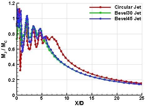
Figure 8. Jet centerline decay of Mach 2.17 over-expanded jet at NPR 6
The jet, at NPR 6, is overexpanded with an overexpasion level of about 41%. It is interesting to see that, the centerline velocity decay of the Bevel45 jet completely overlaps with the Bevel30 jet. This shows that, at NPR 6 both the bevelled nozzles (Bevel30 and Bevel45) reduce the jet core at the same rate as that of nozzle with no exit inclination (circular nozzle). The core length of the circular jet extends to about 7D downstream of the nozzle exit. However, that of Bevel30 and Bevel45 jets equally extend to about 5.5D downstream of the nozzle exit. Thus, the core length reduction of about 21 % is reported with nozzle exit inclination of 300 and 450 as compared to nozzle with zero exit inclination. The same number of shock-cells are also reported for the jets from both the bevel nozzles. However, the shock-cell length has increased at NPR 6 due to the reduction in the adverse pressure at the nozzle exit. The characteristics decay of jets extends up to 18D, downstream of the nozzle exit and beyond that, the jet profile attains almost self-similar nature.
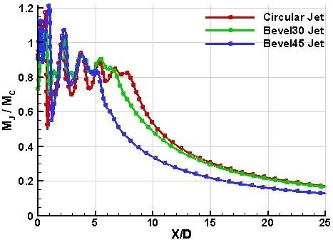
Figure 9. Jet centerline decay of Mach 2.17 over-expanded jet at NPR 7
The jet centerline velocity decay results at NPR 7 are shown in Figure 9. At this NPR, the jet is found to be overexpanded with an overexpansion level of about 31 %. It is seen that, except in the near-field of the nozzle exit, the jet from the circular, Bevel30 and Bevel 45 nozzles show distinct jet centerline velocity decay. The jet core of the circular nozzle is highest among all the jets under study, whereas the core length of the jet from Bevel45 nozzle is the smallest among all. However, the gradients of the characteristic decay zone, reported by the jets from all the nozzles are almost same. This clearly indicates that, the decay rate of all the jets from different nozzles are almost same, when the jets lose the supersonic character, of their respective centerline velocities.
Comparing the centerline decay plots at NPR 5 to 7, it is seen that the peak Mach number at the jet centerline, in the near-field region of the jet, at the nozzle exit, increases with the increase in the NPR. This is in accord with the theory of turbulent jets, as with the decrease in the adverse pressure gradient at the nozzle exit, the jet velocity increases, as it exits the nozzle. The quantitative analysis of the jets in the present study at NPR 7 shows that, the core length of the jet from circular nozzle extends to about 7.5D whereas the core lengths, respectively, from Bevel30 and Bevel45 jets are found to be about 6.5D and 5D. This amounts to a core length reduction of the order of 13% and 33% respectively from the jets from Bevel30 and Bevel45 nozzles.
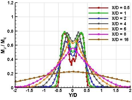
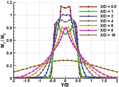
5.2 Mach profiles of the jet
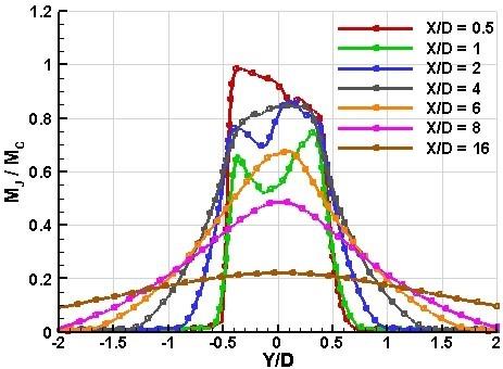
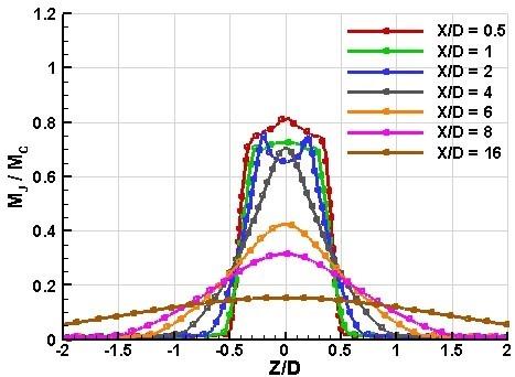
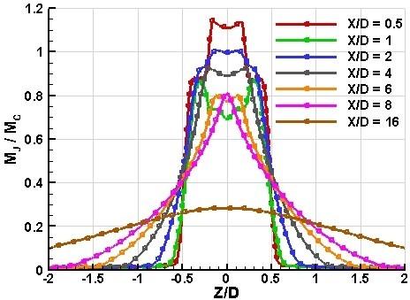
The Mach profiles of the jet issuing from circular, Bevel30 and Bevel45 nozzles are shown in Figures 10 and 11, respectively, for NPR 5 & 7. The Mach profiles are non-dimensional Mach number variation along the directions, normal (Y) and transverse (Z), to the jet centerline. The Mach number profiles are the variations of non-dimensional Mach number at different station values (X/D = 0.5, 1, 2, 4, 6, 8, 16) along the jet centerline in the directions, normal and transverse to the jet axis. The Y and Z profiles show the locations of axis switching, in which the jet cross-section after exiting the nozzle evolves in such a manner that its major axis changes to minor axis and vice versa. It has been established in the literature that an early axis switching leads to rapid jet mixing with the ambient. The Mach profiles of the circular jet at NPR 5 along the normal (Y) and transverse (Z) directions are shown in Figure 10 (a) and 10 (d), respectively. It is seen that, the Mach profiles for the jet from circular nozzle exhibit a considerable symmetry along the Y and Z directions. Also, there are two peaks of the jet velocities located along either side of the jet centerline (Y=0, Z=0), which shows the tendency of jet bifurcation. Further, for X/D = 0.5, which is almost at the first cross-over point, the jet velocity along the centerline decreases. This is in close agreement with the jet centerline velocity decay results, as discussed earlier. It is seen that the locations (X/D = 6 and X/D = 8), represent the onset of characteristic decay zone. Beyond X/D = 8, the jet velocity decreases monotonically, which shows that, the dominance of viscous activity, reaching from the jet boundary to the jet centerline, initiating the fully-developed zone. The axial location X/D = 16 lies at the self-similar zone, which is seen by the, almost, symmetrical nature of the Mach profiles about the jet centerline. The jet issuing from the circular nozzle is almost symmetrical about its axis, due to this the Z profile is almost similar to the Y profile. The vortices generated from the edges of the nozzle exit and from the jet boundary are bound to have their own frequencies, which could not be the same. Thus, a mild asymmetry appears in the Mach profiles along the normal and transverse to the jet axis.
(a)
(b)
(c)
(d)
(e)
(f)
Figure 10. Mach profile of jets at NPR 5: (a), (b), & (c) are the Y-profile of circular, Bevel30, and Bevel45 jet respectively, and (d), (e), & (f) are Z-profile circular, Bevel30, and Bevel45 jet respectively
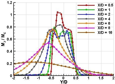
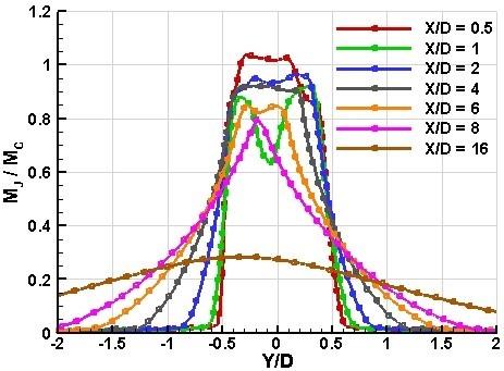
The Mach profiles of the jet from the Bevel30 and Bevel45 nozzles, at NPR 5 are shown in Figure 10 (b), (e) and 10 (c), (f), respectively, along the directions normal and transverse to the jet axis. It is seen that, the transverse direction profiles (Z profiles) of the jet from Bevel30 and Bevel45 nozzles show considerable symmetry about the jet axis. The transverse direction Mach profiles of the jet from Bevel45 nozzle are broader than that for Bevel30 nozzles. The plausible reason for this, is the vortex turning, causing increased jet spread along the Z direction. Further, the Mach profiles along the Y direction also show the similar nature, exhibiting increased rate of jet spread. The Bevel30 and Bevel45 nozzle cause substantial asymmetry of the jet which is clear from the Y direction Mach profiles. It is seen from the Mach profiles of the jet from Bevel30 and Bevel45 nozzles that, the axis of the jet is not the geometric axis. This is because of the exit plane inclination given at the nozzle exit. Thus, for the bevelled nozzles, the axis of the jet is no more the geometric axis of the nozzle exit, rather it is the slip-line formed due to the shock interaction of opposite families at which sudden jump in the entropy takes place. Due to the different shock deflection angle of the shocks, emerging from the nozzle-lip, the flow turns towards the shock having the more deflection angle [32].
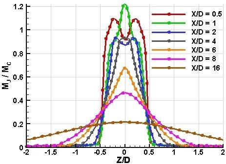
The Mach profiles of the jet from circular, Bevel30 and Bevel45 nozzles at NPR7 are presented in Figures 11 in the directions normal (Y) and transverse (Z) to the jet axis. The increase in the NPR is seen as peak augmentation in the Mach profiles of all the jets of the present study. This is an anticipated result because NPR 7 exhibits comparatively lower level of adverse pressure gradient at the nozzle exit. At this NPR the increased tendency of jet bifurcation is seen for the jets from circular and Bevel30 nozzles. However, the jet from Bevel45 nozzle exhibits increased jet spread. This might be because of the enhanced rate at which the vortex roll-ups are turned as they move downstream of the nozzle exit. At NPR 7, the jet bifurcation is also seen by the jet from Bevel45 nozzle in the direction transverse to the jet axis (Z-direction). This might be attributed to the decreasing level of adverse pressure gradient at the nozzle exit and increased transverse turning of the vortices as they move downstream of the nozzle exit.
It is essential to note that when the flow is symmetrical about the jet centerline (X-axis), the Y-profile and Z-profile were similar to each other, as shown in Figure 10(a) and Figure 10(d), Figure 11(a) and Figure 11 (d). Since with increase in NPR the flow deflection angle of the Bevel30 jet has changed in such a manner that its slip-line almost become closer and parallel to the jet axis (X-axis), so the similar profile of Bevel30 jet is also seen along the Y and Z directions, Figure 11 (b), Figure 11 (e).
At NPR 7, it is nice to see that the Y-profile of the Bevel45 jet (Figure 11 (c), (f)) is entirely different from Bevel30 and circular jet at the same NPR. The Y-profile of Bevel45 at NPR 7 followed completely different trends even when comparing to the Bevel30 jet and Bevel45 jet at NPR 5. With increase in NPR the Bevel45 attains symmetry over the jet centerline (X-axis). This happens due to the shock-shock interaction of the shocks of the opposite families from the nozzle exit with different shock deflection angle. Due to higher shock deflection of the oblique shock emerging from the top edge of the nozzle exit, the gross flow has turned above the X-axis and thus leading to the axis switching right from the nozzle exit leading to highest mixing enhancement compared to other nozzles at NPR 7.
5.3 Flow visualization using Mach contours and numerical shadowgraph images
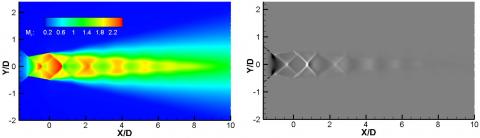
The Mach contours and numerical shadowgraph images of the jet from circular, Bevel30 and Bevel45 nozzles at NPR 5, in the directions normal (Y) and transverse (Z) to the jet centerline, are presented in Figures 12 and Figure 13, respectively.
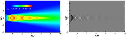
Figure 12 shows the Mach contours and numerical shadowgraph images of the jet at NPR 5 taken normal to the plane containing the centerline of the jet (XY plane such that X is the direction of the jet centerline). In Figure 13, the images are taken normal to the plane XZ (such that X is the direction of the jet centerline), at NPR 5. The jet issuing from the circular nozzle is symmetrical about its lateral and longitudinal axes, so similar Mach contours and shadowgraph images are seen for the circular jet along the plane containing the centerline of the jet (normal to the planes XY and XZ) as shown Figures 12 (a) and Figure 13(a), respectively. The four cross-over points of the shocks at the exit of the circular nozzle are clearly visible in the numerical shadowgraph images. The shock diamonds; as seen from Figures 12 (a) and Figure 13(a) are only appeared from the shadowgraph images; not from the Mach contours. That is why both the Mach contours and shadowgraph images are presented for better qualitative visualizations of shocks.
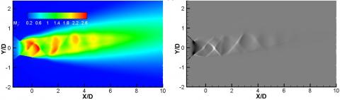
The initial shock-cell of the circular jet is stronger in strength which reduces thereafter, as the jet propagates further. The total number of four shock-cells are clearly seen from the images of the circular jet. However, the fifth shock-cell that was seen in the centerline velocity decay plot (Figure 7) could not appear due to its feeble strength. The Mach contours and numerical shadowgraph images of the jet issuing from the Bevel30 nozzle, at NPR 5, are shown in Figure 12 (b) and Figure 13 (b), respectively, normal to XY and XZ planes. It is seen that, the jet is deflected substantially from the geometric axis of the nozzle, as shown in Figure 12 (b). However, the jet maintains its symmetry about the nozzle axis, when viewed normal to the XZ plane, as shown in Figure 13 (b). The reason for higher core reduction, achieved from the Bevel30 nozzle could be attributed to the fact that, the vortex roll-up inclination gradually increases downstream, as the jet propagates. This is seen from the numerical images showing- the deflection of the jet from the nozzle axis (Figure 12(b)). The three and four number of shock-cells, which were respectively seen for the jets from Bevel30 and Bevel45 nozzles from the centerline velocity decay plot at NPR 5 are shown in the contours and shadowgraph image along the planes containing the jet centerline. It is interesting to see that, the Bevel30 nozzle alter the symmetrical diamond shock; which appeared from the circular nozzle; into an asymmetrical shock structures and thus weaken the shock strength. The flow about the jet centerline is almost symmetrical (when viewed normal to the XZ plane, as in Figure 13(b)), and the highest core reduction is seen from the Bevel30 at NPR5.
(a)
(b)
(c)
(d)
(e)
(f)
Figure 11. Mach profile of jets at NPR 7: (a), (b), & (c) are the Y-profile of circular, Bevel30, and Bevel45 jet respectively, and (d), (e), & (f) are Z-profile circular, Bevel30, and Bevel45 jet respectively
(a)
(b)
(c)
Figure 12. Jet flow visualization using Mach contours and shadowgraph images on the central XY plane; (a) circular nozzle, (b) Bevel30 nozzle and (c) Bevel45 nozzle at NPR 5
(a)
(b)
(c)
Figure 13. Jet flow visualization using Mach contours and shadowgraph images on the central XZ plane; (a) circular nozzle, (b) Bevel30 nozzle and (c) Bevel45 nozzle at NPR 5
(a)
(b)
(c)
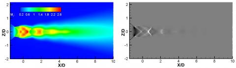
Figure 14. Jet flow visualization using Mach contours and shadowgraph images on the central XY plane; (a) circular nozzle, (b) Bevel30 nozzle and (c) Bevel45 nozzle at NPR 7
(a)
(b)
(c)
Figure 15. Jet flow visualization using Mach contours and shadowgraph images on the central XZ plane; (a) circular nozzle, (b) Bevel30 nozzle and (c) Bevel45 nozzle at NPR 7
The Mach contours and numerical shadowgraph images of the jets under the present study, at NPR 7, are shown in Figures 14 and 15, in the directions normal to the XY and XZ planes, respectively. The jet from the Bevel30 and Bevel45 nozzles show augmentation in shock-cells with NPR. Furthermore, with the increase in the NPR, the jet from the Bevel30 nozzle re-aligns itself from the jet centerline. This is in accord with the Mach profiles, as discussed in the earlier section. The jet from the Bevel45 nozzle exhibit diamond shock pattern with the increasing NPR at the nozzle exit (Figure 15(c)). Also, the jet from Bevel45 nozzle shows increased jet spread, when viewed normal to the XY plane, as shown in Figure 14(c). These two phenomena are strong evidence of increased mixing, which is also in accord with the centerline jet velocity decay results. The jets under the present study maintain symmetry about the jet centerline, when viewed normal to the XZ plane, as shown in Figure 15.
The present study focuses on the numerical investigation of the mixing characteristics of the Mach 2.17 jet from circular, Bevel30 and Bevel45 convergent-divergent nozzles. The exit plane inclinations of angels 30° and 45° are given to the Bevel30 and Bevel45 nozzles, respectively. The results are presented as centerline velocity decay and Mach profiles for NPRs in the range of 5 to 7 with unit steps. The important findings are concluded as follow;
|
A.R. |
aspect ratio |
|
|
a |
Bradshaw constant |
|
|
Bevel30 |
bevel nozzle with bevel angle 30 degrees |
|
|
Bevel45 |
bevel nozzle with bevel angle 45 degrees |
|
|
D |
equivalent diameter of the nozzle exit |
|
|
GIT |
grid independence test |
|
|
k |
turbulent kinetic energy, J. kg-1 |
|
|
Max. |
maximum |
|
|
MJ |
local Mach number of jet |
|
|
MC |
correctly expanded Mach number |
|
|
NPR |
nozzle pressure ratio |
|
|
P |
pressure, N.s.m-1 |
|
|
u |
x-component of velocity, m. s-1 |
|
|
v |
y-component of velocity, m. s-1 |
|
|
w |
z-component of velocity, m. s-1 |
|
|
U |
mean velocity, m.s-1 |
|
|
T |
temperature, K |
|
|
Greek symbols |
||
|
µ |
dynamic viscosity, kg. m-1.s-1 |
|
|
ρ |
density, kg. m-3 |
|
|
ω |
specific rate of dissipation, s-1 |
|
[1] Srivastava, S., Rathakrishnan, E. (2014). Performance of corrugated limiting tab in presence of sharp corners. International Review of Aerospace Engineering, 7(1): 1-7.
[2] Srivastava, S., Kaushik, M. (2015). Supersonic square jet mixing in presence of cross-wire at nozzle exit. American Journal of Fluid Dynamics, 5: 19-23. https://doi.org/10.5923/s.ajfd.201501.03
[3] Lohia, D.K., Kumar, B., Srivastava, S., Paliwal, H.K. (2018). Numerical simulation of supersonic over-expanded jet from 2-D convergent-divergent nozzle. International Journal of Integrated Engineering, 10: 195-201. https://doi.org/10.30880/ijie.2018.10.08.029
[4] Kumar, B., Srivastava, S. (2019). Modelling 2-D supersonic jet from a convergent-divergent nozzle using k-ε realizable turbulence model. Journal of Physics: Conf. Series, 1240(1). https://doi.org/10.1088/1742-6596/1240/1/012019
[5] Rathakrishnan, E. (2009). Experimental studies on the limiting tab. AIAA Journal, 47(10): 2475-2485. https://doi.org/10.2514/1.43790
[6] Wlezien, R.W., Kibens, V. (1988). Influence of nozzle asymmetry on supersonic jets. AIAA Journal, 26(1): 27-33. https://doi.org/10.2514/3.9846
[7] Rice, E.J., Raman, G. (1993). Supersonic Jets from Bevelled Rectangular Nozzles, NASA Technical Memorandum, 10640.
[8] Raman, G. (1996). Screech tones from rectangular jets with spanwise oblique shock-cell structures. In 34th Aerospace Sciences Meeting and Exhibit, p. 643.
[9] Tam, C.K.W., Shen, H., Raman, G. (1997). Screech tones of supersonic jets from bevelled rectangular nozzles. 35th Aerospace Sciences Meeting & Exhibit, January 6-10, Reno, NV. https://doi.org/10.2514/2.232
[10] Viswanathan, K. (2005). Nozzle Shaping for reduction of jet noise from single jets. AIAA Journal, 43(5): 1008-1022. https://doi.org/10.2514/1.11331
[11] Zeng, Y., New, T.H., Chng, T.L. (2011). Flow behaviour of turbulent nozzle jets issuing from bevelled collars. Experimental Thermal and Fluid Science, 35: 1555-1564. https://doi.org/10.1016/j.expthermflusci.2011.07.007
[12] Wu, J., New, T.H. (2017). An investigation on supersonic bevelled nozzle jets. Aerospace Science and Technology, 63: 278-293. https://doi.org/10.1016/j.ast.2017.01.003
[13] Sandhya, M., Tide, P.S. (2018). Computational analysis of subsonic jets from rectangular nozzles with and without bevel. Journal of Spacecraft and Rockets, 55(3): 749-763. https://doi.org/10.2514/1.A34011
[14] Wu, J., Lim, H.D., Wei, X., New, T.H., Cui, Y.D. (2019). Flow characterization of supersonic jets issuing from double-beveled nozzles. Journal of Fluids Engineering, 141(1). https://doi.org/10.1115/1.4040447
[15] Wei, X.F., Chua, L.P., Lu, Z.B., Lim, H.D., Mariani, R., Cui, Y.D., New, T.H. (2020). Experimental investigations on screech mitigation and amplification by bevelled and double-bevelled nozzles. Aerospace Science and Technology, 105782. https://doi.org/10.1016/j.ast.2020.105782
[16] Gutmark, E., Ho, C.H. (1986). Visualization of a forced elliptic jet. AIAA Journal, 24: 684-685. https://doi.org/10.2514/3.9328
[17] Ho, C.H., Gutmark, E. (1987). Vortex induction and mass entrainment in a small aspect ratio elliptic jet. Journal of Fluid Mechanics, 179: 383-405. https://doi.org/10.1017/S0022112087001587
[18] Quinn, W.R. (1989). On mixing in an elliptic turbulent free jet. Physics of Fluids A, 1(10): 1716-1722. https://doi.org/10.1063/1.857536
[19] Hussain, F., Husain, H.S. (1989). Elliptic jets. Part 1. Characteristics of unexcited and excited jets. Journal of Fluid Mechanics, 208: 257-320. https://doi.org/10.1017/S0022112089002843
[20] Husain, H.S., Hussain, F. (1991). Elliptic jets. Part 2. Dynamics of coherent structures: Pairing. Journal of Fluid Mechanics, 233: 439-482. https://doi.org/10.1017/S0022112091000551
[21] Husain, H.S., Hussain, F. (1993). Elliptic jets. Part 3. Dynamics of preferred mode coherent structures. Journal of Fluid Mechanics, 248: 315-361. https://doi.org/10.1017/S0022112093000795
[22] Lee, S.J., Baek, S.J. (1994). The effect of aspect ratio on the near-field turbulent structure of elliptic jets. Flow Measurement and Instrumentation, 5: 170-180. https://doi.org/10.1016/0955-5986(94)90016-7
[23] New, T.H., Tsovolos, D. (2011). On the vortical structures and behaviour of inclined elliptic jets. European Journal of Mechanics B/Fluids, 30: 437-450. https://doi.org/10.1016/j.euromechflu.2011.04.006
[24] Lim, H.D., New, T.H., Mariani, R., Cui, Y.D. (2019). Effects of bevelled nozzles on standoff shocks in supersonic impinging jets. Aerospace Science and Technology, 94: 105371. https://doi.org/10.1016/j.ast.2019.105371
[25] Rathakrishnan, E. (2010). Applied Gas Dynamics. John Wiley & Sons.
[26] Menter, F.R. (1993). Zonal two equation k-ω turbulence model for aerodynamic flows. In 24th AIAA Fluid Dynamics Conference, 93-2906, Oriando, Florida. https://doi.org/10.2514/6.1993-2906
[27] Wilcox, D.C. (2008). Formulation of the k-ω turbulence model revisited. AIAA Journal, 46(11): 2823-2838. https://doi.org/10.2514/1.36541
[28] Hromisin, S., Lempenfield, J., McLaughlin, D.K., Morris, P.J. (2016). Experimental and numerical study of fluidic corrugation design for supersonic jet noise reduction. In 22nd AIAA/CEAS Aeroacoustics Conference, 2016-2989, Lyon, France. https://doi.org/10.2514/6.2016-2989
[29] Morgan, J., Morris, P.J., McLaughlin, D.K., Prasad., C. (2017). Further development of supersonic jet noise reduction using nozzle fluidic inserts. In 55th AIAA Aerospace Sciences Meeting, 2017-0683, Grapevine, Texas. https://doi.org/10.2514/6.2017-0683
[30] Iyogun, Chritopher O., Birouk, M. (2009). Effect of sudden expansion on entrainment and spreading rates of jet issuing from asymmetric nozzles. Flow, Turbulence and Combustion, 82: 287-315. https://doi.org/10.1007/s10494-008-9176-9
[31] Bradshaw, P. (1987). Turbulent secondary flows. Annual Review of Fluid Mechanics, 19(1): 53-74. https://doi.org/10.1146/annurev.fl.19.010187.000413
[32] Anderson, J.D. (2003). Modern Compressible Flow with Historical Perspective, McGraw-Hill Series in Aeronautical and Aerospace Engineering, 3rd ed., 159-161.