Khalid Faisal Sultan | Mohammed Hassan Jabal | Ameer Abed Jaddoa*
© 2021 IIETA. This article is published by IIETA and is licensed under the CC BY 4.0 license (http://creativecommons.org/licenses/by/4.0/).
OPEN ACCESS
This paper presents an experimental analysis on the heat transfer and pressure drop enhancement of oil nanofluid flow. In this analysis, the first method has used the helically coiled tube and shell, the oil nanofluids were employed instead of the base fluid (oil) in the second process. the two techniques were used to improve the heat transfer and pressure drop. Nanofluid oil concentrations utilized within range from 1 to 5 percent vol. This paper applied two forms of nanoparticles: copper (Cu (20 nm)) and zirconium oxide (ZrO2 (40 nm)) and base fluid (oil). The influence on the heat transfer coefficient for different factors such as the flow number of Reynolds, the temperature of the nanofluid oil, the concentration and shape of the nanoparticle, and the pressure gradient of the flow have examined. The results indicated that the value of a 40.35 percent in the heat transfer coefficient for Cu + oil and 28.42 percent for ZrO2 + oil increased compared with the base fluid (oil) at 5 percent vol concentration. Using oil nanofluids (Cu, ZrO2 – oil) instead of the base fluid (oil) led to increasing in the heat transfer coefficient and decreasing the pressure. In addition, the result showed that the heat transfer efficiency has enhanced using the helically coiled tube and shell, as well as increasing in the pressure drop was due to the curvature of the tube. Baes on the relationship between viscosity and shear intensity, the oil nanofluid behaviors were similar to the standard Newtonian fluids. Moreover, the related flow and heat transfer methods are used to present the output index. The exergy inflow, exergy destruction and exergy efficiency of oil nanofluid (Cu +oil) were greater than the oil nanofluid (ZrO2 +oil) and oil. The exergy inflow, exergy destruction, and exergy efficiency for the two type of oil nanofluid increased with increasing of nanoparticles concentration.
oil nanofluids, exergy, spiral heat exchanger, heat transfer, pressure drop
Nanofluid is a uniform dispersion of particles measured by nanometers within a liquid that Choi and Eastman [1] initially pioneered. Many researchers have been motivated to study nanofluid thermal and flow behavior by outstanding nanofluid characteristics such as increased thermal conductivity, long – term stability, and low penalties for increasing pressure drop and tube wall abrasion. These studies concentrate primarily on efficient thermal conductivity, Phase change behavior, tribological properties, the flow of nanofluids, and the transfer of convective heat. In a broad range of experimental and theoretical studies in the past decade on the effective thermal conductivity of nanofluids, the impact on nanofluid thermal conductivity of different parameters such as particle concentration, particle size, mixture temperature and Brownian motion has been tested. The results showed an improvement in the thermal conductivity of nanofluids with increasing in concentration of nanoparticles and temperature of the mixture [2-5]. It has been also indicated that the higher thermal conductivity changes are due to the better particle size [4-6]. The majority of recent research focuses on the activity of convective heat transfer of nanofluids due to the improved of the thermal properties in laminar and turbulent flows, and nanofluids. Nearly, all of these studies report improving the convective transmission of nanofluid heat. Nanofluid convective heat transfer in turbulent flow has been considered by many numerical and experimental studies [7-10]. The conversion of nanofluids to convective heat in laminar flow has been studied in many other studies. Al2O3 / water nanofluid heat transfer was investigated by the authors [11] and has been reported under constant wall heat flux in the laminar flow. it noticed an increasing in the coefficient of nanofluid heat transfer with an increasing in the number of Reynolds and in the concentration of nanoparticles. Practically, in the entry area [12] investigated in a laminar regime with a constant thermal flux wall boundary state, the convective heat transfer of CNT nanofluids. At Re = 800 and CNT percent / nanofluid water, they recorded a cumulative increasing of 350 percent in a coefficient of convective heat transfer of 0.5 wt. A few studies have investigated the characteristics of the friction component of nanofluid flow in addition to convective heat transfer. The completely established the convective heat transfer and friction factor characteristics of Al2O3 / water nanofluid that flowing through a uniformly heated horizontal tube with and without wire coil inserts which investigated by Xuan and Li [13] in laminar flow. They have decided that the Nusselt figure increased up to 12.24 percent with a volume concentration of 0.1 percent compared with that nanofluid purified water. Nevertheless, under the same Reynolds numbers, the friction factors of the same nanofluid were nearly identical to those of water. using of the helical tubes instead of straight tubes is another heat transfer raising technique. Helical tubes were introduced as a one of the passive heat transfer enhancement strategies due to their compact construction and elevated heat transfer coefficient. They are widely used in different industrial applications, for example, methods of heat recovery, air conditioning and cooling systems, chemical reactors, food processes and milk processes. The researchers thoroughly single – phase heat transfer properties tested in the helical tubes experimentally and theoretically and contrasted the heat transfer levels between a helically coiled heat exchanger and a straight-tube heat exchanger [14]. The results showed that the heat transfer coefficient was influenced by the geometry of the heat exchanger and the water bath temperature that surrounded by the heat exchanger. In both of the vertical and horizontal helical annular pipes, many researchers studied an influence of the coil geometries, air and water flow levels on the pressure drops [15]. Three separated inner and outer tube diameters were determined in the trial sections. The results have shown that a wide variety of Reynolds numbers are protected by the transformation from laminar to turbulent flow. A friction factor correlation was established based on the experimental results. The mean deviation from experiments and the relationship between the friction factors was found to be 15 percent. The spherical Al2O3 was used by [16]. Rod shape and AIN spherical nanoparticles dispersed in transformer oil to create nanofluids. At Reynolds number ranges from 100 to 500, the heat transfer coefficient of all three types of nanofluids indicated a small increasing. For nanoparticles based on AIN / transformer oil with a volume fraction of 0, a cumulative increasing of 20 per cent was observed. It found that a central mechanism regulating the thermal behavior of nanoparticle–fluid suspensions ("nanofluids") is the Brownian motion of nanoparticles at the molecular and nano scale stage. Another study has developed a theoretical model that accounts for dynamic nanoparticles' fundamental function in nanofluids. Not only does the model capture concentration and temperature-dependent conductivity, but it also strongly predicts the size – dependent conductivity. In addition, they found a fundamental distinction in size – dependent conductivity between solid/solid composites and solid/liquid suspensions. This understanding could lead to the design of next – generation Nano engineered coolants in high – heat – flux cooling with industrial and biomedical applications [17]. The thermal conductivity and viscosity of the liquids are influenced by the dispersion of the tiny c-aluminum oxide particles (Al2O3), Silicon Dioxide (SiO2) and Dioxide of Titanium [18]. To model the convection heat transfer of the Carbon nanotube based nanofluids, a numerical analysis based on LBM was presented. The results showed that the adding of a small amount of carbon nanotube to the base of fluid resulted in a major increasing in convection rate [19]. The measured thermal conductivity phenomenon has been evaluated to be greater than the theoretical expectations and nonlinear with fullerene loadings. The elemental limits of standard heat conductivity models for solid or liquid suspensions are shown by these phenomena [20]. They have found that a key mechanism that is regulating the thermal behavior of nanoparticle – fluid suspensions may be the movement of nanoparticles at the molecular and nanoscale level [21].
The aims of this paper are to assess the performance of energy and exergy through oil nanofluid inlet and outlet temperature and efficiency of exergy. In addition, multiple variables have been tested that could affect the improvement of the oil nanofluid coefficient of heat transfer that including the size of nanoparticles, volume fraction, number of Reynolds, and temperature of nanofluids.
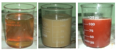
The oil nanofluid that used in this work is formed by nanoparticles of cupper (Cu (20 nm)) and zirconium oxide (ZrO2) (40 nm), and the two step methods were used for the preparation of nanofluids. Nanofluid samples were prepared in base fluid (Oil) by dispersing pre weighted amounts of dry particles. In order to breakdown any particle aggregates, [100 kHz, 300 W at 25 to 30℃, and Toshiba, England] ultrasonic mixing was employed and then exposed to the mixtures for one hour. In this scientific nanofluid, Motor oil and nanoparticles (Castrol Company) (GTX) 20W50 (US Science Nano Materials, Inc) were identified. The main characteristics are presented in Tables 1 and 2. Figure 1 displays the image containing nanofluids (Cu (20 nm)) and oxide zirconium (ZrO2) (40 nm) with different percentage of volume (Ф = 1, 3, and 5 vol %).
Table 1. Properties of engine oil [22]
|
Base fluid |
SAE 20W50 |
|
ρ (Kg/m3) |
893 |
|
ν (cSt) |
17 |
|
Index of viscosity |
115 |
|
Total carbonation (mgKOH/g) |
6 |
|
Minimum for Point of ignition |
214 |
|
Minimum Point of Pouring (℃) |
– 24 |
Table 2. Properties of nanoparticles [23]
|
Base fluid |
Ρ (Kg/m3) |
Cp (J/kg k) |
K (W/m k) |
α *105 (m2/s) |
|
Copper (Cu(20nm)) |
8933 |
385 |
401 |
11.7 |
|
Zirconium oxide (ZrO2 (40nm)) |
5890 |
278 |
22.7 |
12.4 |
Figure 1. Depicted oil nanofluids to Oil, ZrO2 + Oil and Cu + Oil
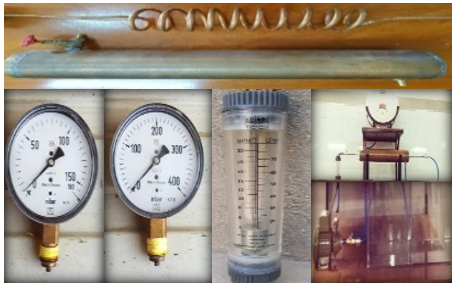
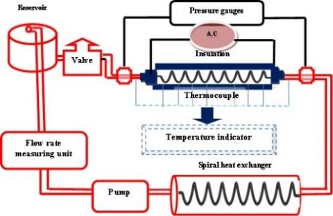
The heat exchanger or test segment has 10 mm of inner dimeter, 12 mm outer diameter as a helically tube with 10 turns and 1000 mm length with shell length has 150 mm inside, 160 mm outer diameter and a length of 1250 mm. The helically coiled side loop tube and side loop shell of the device. According to the cupper, two types of oil nanofluids and zirconium oxide – oil are treated by the side loop of the helically coiled tube. The lateral shell loop manages hot oil. Shell side loop consists of 20 L capacity storage vessel with 5 Kw heater, thermostat, pump, and power valve. The side loop of the helically coiled tube is a test segment containing shell and spiral tube and pump [Bosch 1046-AE]. Hot oil temperature hand storage vessel in the shell is controlled by the thermostat, needle valve, flow meter (MMA mini-master flow meter of the Dwyer series) with a selection of (1–20 Lpm). Four T–style 0.15℃ precision thermocouples are used to test the shell and tube side inlet and outlet temperatures. To prevent the leakage, thermocouples are put in, and coated with epoxy. To measure the pressure drop, the pressure gauges are mounted around the helical tube. The shell is lined with fiberglass sleeving that coated with acrylic resin to minimize the heat transfer from the shell to the environment. After completion of the flow loop construction and calibration, oil was tested before nanofluid, and testing the functionality of the Nusselt number and viscous pressure loss calculation loop. Complete numbers for the test were 200. Hot oil and cold oil were passed to the side of the shell and pipe to check the circuit leakages and the thermocouples, thermostat were tested. Nanofluids of oil (Cu+ oil and ZrO2 + oil) circulated through the spiral tube side at a volume concentration (Ф = 1, 3 and 5 vol %). Once oil reaches a specified temperature, the shell side pump is turned on. This is achieved by connecting the thermostat in the oil storage device. The flow configuration was rendered in condition of counter flow. After reaching the steady state, the corresponding temperatures were registered. The same procedure was performed for 5 vol % nanofluid oil. It follows the same procedure, and records the temperatures. During analysis process, the shell side flow rate (5 Lpm) and the pitch of the coiled tube remains steady. On the tube side, the flow rate is different. The side flow rate of the coil tube ranges from 5–20 Lpm. Figures 2 and 3 show a photograph of the test segment and the test rig.
Figure 2. Parts of the test system
Figure 3. Schematic plot for research system
The thermo – physical properties of the oil nanofluid were determined by the following equations at the average bulk temperature of the oil – based nanofluid.
Density [24].
${{\text{ }\!\!\rho\!\!\text{ }}_{\text{nf}}}=\Phi \ {{\text{ }\!\!\rho\!\!\text{ }}_{\text{s}}}\ +\left( \text{1}\ -\text{ }\!\!\Phi\!\!\text{ } \right)\ {{\text{ }\!\!\rho\!\!\text{ }}_{\text{oil}}}$ (1)
Viscosity [24].
$\mu_{\mathrm{nf}}=(1+2.5 \Phi) \mu_{\mathrm{oil}}$ (2)
Specific heat [24].
$\text{C}{{\text{p}}_{\text{nf}}}\ {{\text{ }\!\!\rho\!\!\text{ }}_{\text{nf}}}=\Phi \left( {{\text{ }\!\!\rho\!\!\text{ }}_{\text{s}}}\ \text{C}{{\text{p}}_{\text{s}}} \right)+\left( \text{1}-\Phi \right)\ \left( {{\text{ }\!\!\rho\!\!\text{ }}_{\text{oil}}}\text{C}{{\text{p}}_{\text{oil}}} \right)$ (3)
An efficient thermal conductivity model (Eq. (4)) has recently been proposed by [25].
$\frac{\mathrm{k}_{\mathrm{nf}}}{\mathrm{k}_{\text {oil }}}=\left[\frac{\mathrm{Cp}_{\mathrm{nf}}}{\mathrm{Cp}_{\text {oil }}}\right]^{-0.023}\left[\frac{\rho_{\mathrm{nf}}}{\rho_{\text {oil }}}\right]^{1.358}\left[\frac{\mu_{\text {oil }}}{\mu_{\mathrm{nf}}}\right]^{0.126}$ (4)
The heat transfer for oil is estimate by Eq. (5).
$Q_{\text {oil }}=\dot{\mathrm{m}}_{\text {oil }} \mathrm{C}_{\mathrm{p} \text { oil }}\left(\mathrm{T}_{\text {out }}-\mathrm{T}_{\mathrm{in}}\right)_{\mathrm{oil}}$ (5)
The total heat transfer coefficient, Uo, was determined using the following equation [21]:
$\mathrm{U}_{\mathrm{o}}=\frac{\mathrm{Q}_{\mathrm{oil}}}{\mathrm{A}_{\mathrm{o}} \mathrm{LMTD}}$ (6)
where, Ao is the surface area; Qoil is the rate of heat transfer; and LMTD is the log mean difference in temperature based on the difference in inlet temperature (∆T1) and the difference in outlet temperature (∆T2).
$L M T D=\frac{\left(\Delta T_{2}-\Delta T_{1}\right)}{\ln \left(\frac{\Delta T_{2}}{\Delta T_{1}}\right)}$ (7)
$Q=h_{i} A_{i}\left(T_{w}-T_{b}\right)$ (8)
$N u_{i}=\frac{h_{i} d_{i}}{k_{n f}}$ (9)
Eqns. (6) and (8) determine the coefficient of inner heat transfer and the total heat transfer coefficient of the coiled tube respectively. From Eq. (9), the Nusselt number is determined. This measures the transition within the helical tunnel of convective heat. The total coefficient of heat transfer can be related to the inner and outer coefficients of heat transfer by the following equation [26]:
$\frac{1}{\mathrm{U}_{\mathrm{o}}}=\frac{\mathrm{A}_{\mathrm{o}}}{\mathrm{A}_{\mathrm{i}} \mathrm{h}_{\mathrm{i}}}+\frac{\mathrm{A}_{\mathrm{o}} \ln \left(\frac{\mathrm{D}_{\mathrm{i}}}{\mathrm{d}}\right)}{2 \pi \mathrm{kL}}+\frac{1}{\mathrm{~h}_{\mathrm{o}}}$ (10)
where, Di is the inner shell diameter; d is the inner spiral tube diameter; K is the cupper wall's thermal conductivity; and L is the heat exchanger’s length. The Nusselt number is defined by the following description on the shell side.
$\mathrm{Nu}_{\mathrm{o}}=\frac{\mathrm{h}_{\mathrm{o}} \mathrm{D}_{\mathrm{h}}}{\mathrm{k}_{\mathrm{nf}}}$ (11)
where, Dh is the hydraulic shell diameter measured on the basis of the following formula:
$\mathrm{D}_{\mathrm{h}}=\frac{4\left(\mathrm{~V}_{\text {shell }}-\mathrm{V}_{\text {tube }}\right)}{\pi(\mathrm{D}+\mathrm{d})\left(\mathrm{L}_{\text {shell }}+\mathrm{L}_{\text {tubbe }}\right)}$ (12)
Similar to the heat transfer coefficient, for the range of Dean number (De) of (11.6 < De < 2000), the friction factor for laminar flow within helical coiled pipe can is correlated as [27]:
$\frac{f}{f_{s}}=\left[1-\left[1-\left(\frac{11.6}{D_{e}}\right)^{0.45}\right]^{2.22}\right]^{-1}$ (13)
where:
$D_{e}=R_{e} \sqrt{\left(\frac{d}{D_{e}}\right)}$ (14)
The friction factor for helical coiled tube (f) is determined by [27]:
$f_{e}=\frac{7.0144}{R_{e}} \sqrt{D_{e}}$ (15)
The pressure drop of nanofluid in coil tubes is evaluated by:
$\Delta P=f \frac{L \rho V^{2}}{D 2}$ (16)
The loss of energy is estimated by [28]:
Exergy loss= Exergy inflow – Exergy outflow
$E_{x L}=E_{x i}-E_{x 0}$ (17)
The helical coiled tube exergy inflow is shown below.
$E x_{i n f}=\dot{m}_{n f} C p_{\mathrm{nf}}\left[\left(\mathrm{T}_{\mathrm{nf} 1}-\mathrm{T}_{\mathrm{a}}\right)-\mathrm{T}_{\mathrm{a}}\left(\ln \frac{\mathrm{T}_{\mathrm{nf} 1}}{\mathrm{~T}_{\mathrm{a}}}\right)\right]$ (18)
The helical coiled tube exergy outflow is described below.
$E x_{o n f}=\dot{m}_{n f} \mathrm{Cp}_{\mathrm{nf}}\left[\left(\mathrm{T}_{\mathrm{nf} 2}-\mathrm{T}_{\mathrm{a}}\right)-\mathrm{T}_{\mathrm{a}}\left(\ln \frac{\mathrm{T}_{\mathrm{nf} 2}}{\mathrm{~T}_{\mathrm{a}}}\right)\right]$ (19)
Exergy efficiency is determined by:
Exergy Efficiency $=\frac{\text { Exergy inflow - Exergy loss }}{\text { Exergy inflow }}$ (20)
Exergy Efficiency $=1-\frac{\text { Ex } \mathrm{L}}{\text { Exi }}$ (21)
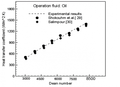
Using the coefficients of heat transfer, oil as the operation fluid, are experimentally calculated until receiving the nanofluids from Cu and ZrO2, and based on oil in order to verify the accuracy and reliability of the experimental system. The findings of the experimental coefficient of heat transfer and pressure drop are compared to those of the [27, 28] and [27] experiments. Figures 4-7 represent thermal properties used for two kinds of nanofluids. For helical coiled heat exchanger flow is described as below.
$\mathrm{Nui}=0.112 \mathrm{De}^{0.51} \mathrm{\gamma}^{-0.37} \operatorname{Pr}^{0.72}$ (22)
$\mathrm{Nuo}=5.48 \mathrm{Re}_{0}^{0.511} \gamma^{0.546} \operatorname{Pr}^{0.226}$ (23)
The difference between theoretical values and experimental values for the coefficient of heat transfer is shown in Figure 8. Strong alignment between these values is seen from this figure as well. Figure 9 indicates the variation between the theoretical values for the pressure drop in the test section and the observed pressure drop. The experiments are performed in the same state and explained in the validation of heat transfer. Base on Figure 9, there is a deviation between 2% and + 4% of the experimental results from the theoretical one.
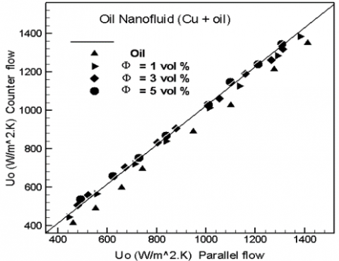
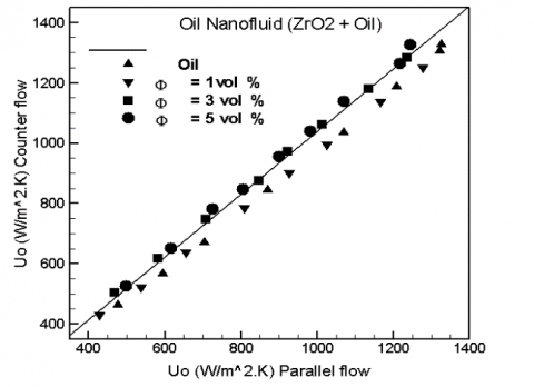
For laminar flow conditions, Oil based Cu, ZrO2 oil nanofluids flowing within the spiral heat exchanger are characterized by the heat transfer and pressure drop characteristics, having developed trust in the experimental system, are experimentally investigated under constant wall temperature. Note, that in the findings below, heat transfer and pressure drop data are not accomplished under exactly the same Reynolds numbers for either of the two separate cases. This is because the oil-dependent viscosity of the nanofluid depends very much on the fraction of the nanoparticle's fluid temperature and length. The counter flow versus the parallel flow overall heat transfer coefficients are plotted in Figures 10 and 11 for two types of oil nanofluids (Cu + oil), and (ZrO2 + oil). There is a reasonable agreement between the two values. In the case of counter flow and two types of oil nanofluids (Cu + oil) and (ZrO2 + oil), the average heat transfer coefficient at 1 vol percent was 4 – 10% higher than the parallel flow, while the average heat transfer coefficient for counter flow was 20–43% higher than parallel flow at 5 vol percent volume fraction.
Heat transfer is found to have no significant effect on changing of flow conditions. The explanation is that the primary flow on the tube side and the production of secondary flow are always perpendicular to the flow on the shell side. Therefore, the variation in the direction of flow does not affected by the overall transfer of heat. The outcomes were identical to parallel flow from the counter flow configuration.
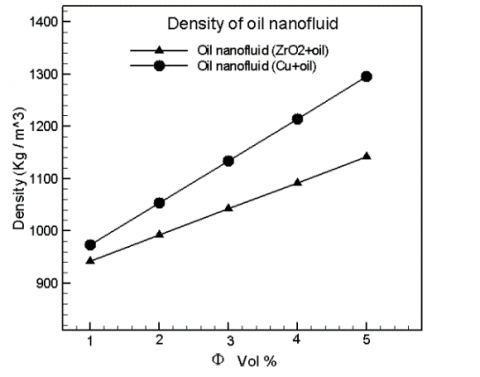
Figure 4. Nanofluids density for (Cu + oil) and (ZrO2 + oil) at various fractional volumes
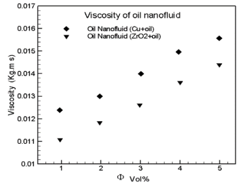
Figure 5. Nanofluids viscosity for (Cu + oil) and (ZrO2 + oil) at various fractional volumes
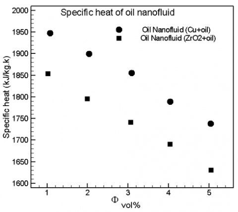
Figure 6. Nanofluids specific heat for (Cu + oil) and (ZrO2 + oil) at various fractional volumes
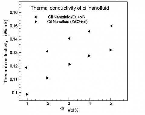
Figure 7. Nanofluids thermal conductivity for (Cu + oil) and (ZrO2 + oil) at various fractional volumes
Figure 8. Comparison of the measured coefficient of Heat transfer with that estimated from [27, 28]
Figure 9. Comparison of theoretical and experimental declines in base oil pressure
Figure 10. Comparison of the counter total heat transfer coefficient and oil nanofluid parallel flow configuration (Cu + oil)
Figure 11. Comparison of the counter total coefficient of heat transfer and oil nanofluid parallel flow configuration (ZrO2 + oil)
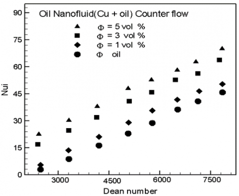
Figures 12 & 13 showed the discrepancy between the internal Nusselt number versus the Dean number with different nanoparticle concentrations for the movement of base oil and oil nanofluids (Cu + oil and ZrO2 + oil). It is observed that when nanoparticle concentration is higher, the inner Nusselt number increases. This is due to a higher coefficient of inner heat transfer and thermal conductivity.
Figure 12. Internal Nusselt oil number nanofluid (Cu + oil) with counter flow
Figure 13. Internal Nusselt oil number nanofluid (ZrO2 + oil) with counter flow
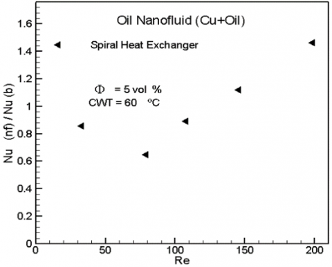
As a function of the helical tube and Reynolds number of oil nanofluids, Figures 14 & 15 show the ratios of 5 vol per cent of Nusselt oil nanofluids to base oil. It is noted that, as they flow within the helical channel, oil nanofluids (Cu + oil and ZrO2 + oil) have better heat transfer effectiveness.
The findings clearly show that the highest Nusselt number ratios for the helical tunnel are obtained at nearly the same Reynolds number range. For example, for the helical tube, a maximum increase of 38.04 percent (Cu + Oil) and 21.13 percent (ZrO2 + Oil) in the Nusselt number ratio is obtained for a range of Reynolds numbers between 100 and 600. The improved chaotic motion of the nanoparticles within the helical tunnel may be attributable to this phenomenon.
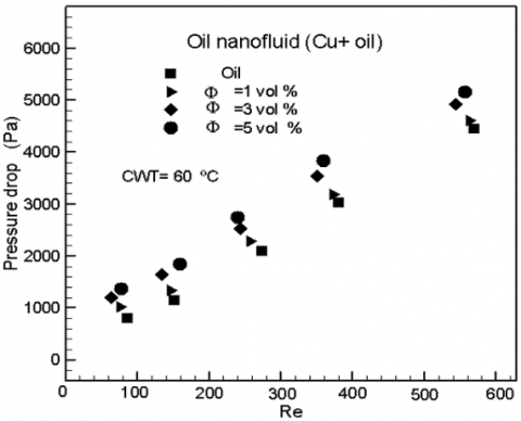
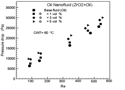
The shear rate will increase the non – uniformity across the cross section, because the shear rate is high when to be near the wall of the helical tunnel, and the nanoparticles are thus more motivated by the variance in the shear rate. According to the ZrO2 + base oil nanofluids with varying volume concentrations for the movement of base oil and Cu, the estimated pressure drop is shown in Figures 16 & 17 as a function of the Reynolds number along the helical channel. The results show at 1 vol per cent nanoparticle concentration, the oil nanofluid pressure gradient is significantly increased relative to the value of oil. For oil nanofluids with greater volume concentration, this enhancement pattern appears to continue. This is due to the fact in contrast to the base fluid, suspending rigid objects in a fluid normally increases the dynamic viscosity.
Figure 14. The Nu ratio of oil nanofluid (Cu + oil) in HE at Φ=5 vol %
Figure 15. The Nu ratio of oil nanofluid (ZrO2 + oil) in HE at Φ=5 vol %
Figure 16. Nanofluid oil pressure drop (Cu + oil) with counter flow at different Φ
Figure 17. Nanofluid oil pressure drop (ZrO2 + oil) with counter flow at different Φ
Figure 18. Oil Nanofluid (Cu + oil) efficiency index with counter flow at different Φ
Figure 19. Oil Nanofluid (ZrO2 + oil) efficiency index with counter flow at different Φ
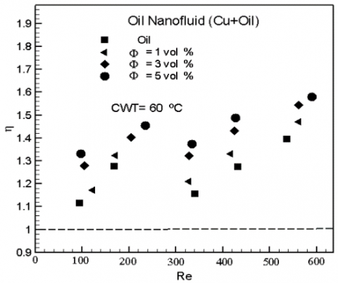
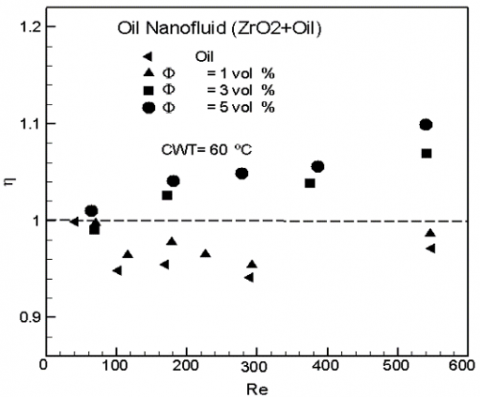
Because viscosity is directly linked to a drop in pressure, higher values of viscosity lead to an increasing the drop of pressure. The overall pressure drop increased of 23.20 per cent (Cu + oil) and 11.14 per cent (ZrO2 + oil), and its achieved when the oil nano fluid with 1 vol per cent concentration is used instead of base fluid. Figures 18 & 19 show that the efficiency index for nanofluids with concentrations of 1, 3 and 5 vol. percent alone was greater than 1. For nanofluids (Cu + oil) and (ZrO2 + oil) with a concentration of 5 vol per cent, a maximum output index of 1.62 and 1.1 has obtained at Reynolds number of 575. From these numbers, it is also shown that all the helical tube concentrations have output indexes greater than 1. This implies that the rate of increasing in the pressure drop is lower for base flow along the spiral tube than for the rising in the coefficient of heat transfer.
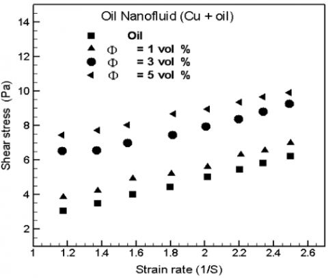
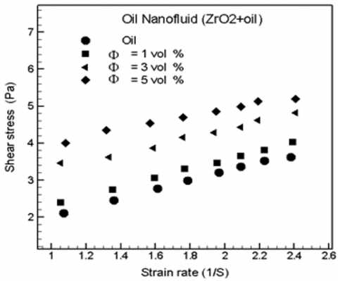
Figures 20 & 21 show that the shear stress of the flow curve is plotted against the shear rate for Cu, and ZrO2 – oil nanofluids at the concentration of particle volume of 1, 3, and 5 vol percent. For these types of nanofluids, the plot data is not parallel, which means that the materials are a Newtonian fluid over this continuum of shear stress.
Figure 20. Shear stress of oil Nanofluid (Cu + oil) with counter flow
Figure 21. Shear stress of oil nanofluid (ZrO2 + oil) with counter flow
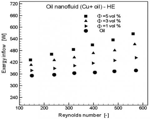
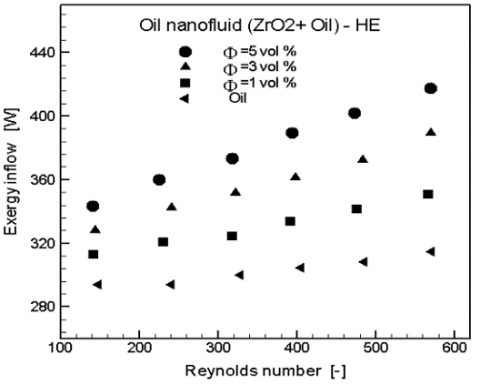
Moreover, with increasing of the shear intensity, shear stress increases for Cu and ZrO2 – oil nanofluids. Using a heat exchanger spiral coil, these figures showed the Cu flow curve and ZrO2 – oil nanofluids measured. With an increasing the concentration of nanoparticles for both parallel flow and counter flow, the shear stress of the nanofluids increases. Based on the second law of thermodynamics, exergy in flow, exergy destruction as well as exergy efficiency is the parameters that used to investigate the characteristics performance of the spiral heat exchanger. In Figures 22 and 23, the inflow values of the exergy are varied with the Reynolds number. The values exergy inflow increased with increasing the Reynolds number for all concentrations. This is due to constant inlet conditions (inlet oil nanofluid temperature and heat flux).
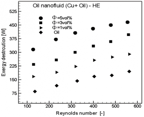
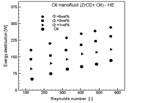
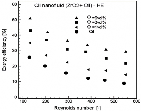
In Figures 24 & 25, the exergy destruction is varied with increasing the Reynolds number. Destruction values are observed to increase with increasing the Reynolds number, and be high at the concentration of 5 vol %. This increasing is due to increasing in pressure drop and increasing in temperature difference between inlet and outlet oil nanofluid. Besides, the exergy destruction found to have a proportional relation with the concentration of the nanoparticles. The highest values of exergy destruction are at 5 vol%, whereas the lowest values are at l vol %. The highest value of Re was 600 for all concentrations. The exergy destruction of the oil nanofluid is greater than the exergy destruction of oil. In Figures 26 & 27, the variation of the exergy efficiency with Reynolds number has shown. From this figure, it is clearly seen that the exergy efficiency decreased with increasing of Reynolds number to all concentrations. On the other hand, the exergy efficiency noticed to be decreased with decreasing the concentration. The highest efficiency is obtained at the highest concentration of the nanoparticles. The lower exergy efficiency occurs at concentration of 1 vol %.
Figure 22. Exergy inflow of oil nanofluid (Cu + oil) in HE at different Φ
Figure 23. Exergy inflow of oil nanofluid (ZrO2 + oil) in HE at different Φ
Figure 24. Exergy destruction of oil nanofluid (Cu + oil) in HE at different Φ
Figure 25. Exergy destruction of oil nanofluid (ZrO2 + oil) in HE at different Φ
Figure 26. Exergy efficiency of oil nanofluid (Cu + oil) in HE at different Φ
Figure 27. Exergy efficiency of oil nanofluid (ZrO2 + oil) in HE at different Φ
The Exergy inflow, exergy destruction and exergy efficiency of oil nanofluid (Cu + oil) are greater than oil nanofluid (ZrO2 + oil) and oil due to thermal properties such as the thermal conductivity, particles size and kind of the nanoparticles.
The Exergy inflow, exergy destruction, and exergy efficiency for the two types of oil nanofluid increased with increasing in the concentration of nanoparticles due to the thermal properties for two types of oil nanofluids such as the thermal conductivity, viscosity, and density.
Based on previous results and discussions, the following conclusions are:
1. The form and size of the nanoparticle plays an important role in improving the heat transfer rate. As the particle size of copper is less than the particle size of oxide zirconium, thus it is the best improvement from the second type. Also, the first type of mineral nano oil is the best improvement from the second type of oxide mineral oil due to the thermal conductivity of the metallic type.
2. The efficiency index for the metal oil nanofluid is greater than the efficiency index for the oxide oil nanofluid relative to the base oil flow.
3. The pressure drop of metal oil nanofluids is greater than the pressure drop of oxide oil nanofluids relative to oil flow.
4. An Exergy in flow, exergy destruction and exergy efficiency of oil nanofluid (Cu + oil) are greater than oil nanofluid (ZrO2 + oil) and oil.
5. The Exergy inflow, exergy destruction, and exergy efficiency for the two type of oil nanofluid increased with increasing in concentration of nanoparticles.
[1] Choi, S.U.S., Eastman, J.A. (1995). Enhancing thermal conductivity of fluids with nanoparticles. International Mechanical Engineering Congress and Exhibition, San Francisco, CA (United States), pp. 99-105.
[2] Chandrasekar, M., Suresh, S., Bose, A.C. (2010). Experimental investigations and theoretical determination of thermal conductivity and viscosity of Al2O3/water nanofluid. Experimental Thermal and Fluid Science, 34(2): 210-216. https://doi.org/10.1016/j.expthermflusci.2009.10.022
[3] Yu, W., Xie, H.Q., Chen, L.F., Li, Y. (2010). Enhancement of thermal conductivity of kerosene based Fe3O4 nanofluids prepared via phase-transfer method. Colloids and Surfaces A: Physicochemical and Engineering Aspects, 355(1-3): 109-113. https://doi.org/10.1016/j.colsurfa.2009.11.044
[4] Mintsa, H.A., Roy, G., Nguyen, C.T., Doucet, D. (2009). New temperature dependent thermal conductivity data for water-based nanofluids. International Journal of Thermal Sciences, 48(2): 363-371. https://doi.org/10.1016/j.ijthermalsci.2008.03.009
[5] Vajjha, R.S., Das, D.K. (2009). Experimental determination of thermal conductivity of three nanofluids and development of new correlations. International Journal of Heat and Mass Transfer, 52(21-22): 4675-4682. https://doi.org/10.1016/j.ijheatmasstransfer.2009.06.027
[6] Karthikeyan, N.R., Philip, J., Raj, B. (2008). Effect of clustering on the thermal conductivity of nanofluids. Materials Chemistry and Physics, 109(1): 50-55. https://doi.org/10.1016/j.matchemphys.2007.10.029
[7] Fotukian, S.M., Esfahany, M.N. (2010). Experimental study of turbulent convective heat transfer and pressure drop of dilute CuO/water nanofluid inside a circular tube. International Communications in Heat and Mass Transfer, 37(2): 214-219. https://doi.org/10.1016/j.icheatmasstransfer.2009.10.003
[8] Pak, B.C., Cho, Y.I. (1998). Hydrodynamic and heat transfer study of dispersed fluids with submicron metallic oxide particle. A Journal of Thermal Energy Generation, Transport, Storage, and Conversion, 11(2): 151-170. https://doi.org/10.1080/08916159808946559
[9] Williams, W., Buongiorno, J., Hu, L.W. (2008). Experimental investigation of turbulent convective heat transfer and pressure drop of alumina/water and zirconia/ water nanoparticle colloids (nanofluids) in horizontal tubes. Journal of Heat Transfer, 130(4): 042412. https://doi.org/10.1115/1.2818775
[10] He, Y.R., Jin, Y., Chen, H.S., Ding, Y.L., Cang, D.Q., Lu, H.L. (2007). Heat transfer and flow behavior of aqueous suspensions of TiO2 nanoparticles (nanofluids) flowing upward through a vertical pipe. International Journal of Heat Mass Transfer, 50(11-12): 2272-2281. https://doi.org/10.1016/j.ijheatmasstransfer.2006.10.024
[11] Wen, D.S., Ding, Y.L. (2004). Experimental investigation into convective heat transfer of nanofluids at the entrance region under laminar flow conditions. International Journal of Heat and Mass Transfer, 47(24): 5181-5188. https://doi.org/10.1016/j.ijheatmasstransfer.2004.07.012
[12] Ding, Y.L., Alias, H., Wen, D.S., Williams, R.A. (2006). Heat transfer of aqueous suspensions of carbon nanotubes (CNT nanofluids). International Journal of Heat and Mass Transfer, 49(1-2): 240-250. https://doi.org/10.1016/j.ijheatmasstransfer.2005.07.009
[13] Xuan, Y.M., Li, Q. (2003). Investigation on convective heat transfer and flow features of nanofluids. Journal of Heat Transfer, 125(1): 151-155. https://doi.org/10.1115/1.1532008
[14] Chandrasekar, M., Suresh, S., Bose, A.C. (2010). Experimental studies on heat transfer and friction factor characteristics of Al2O3/water nanofluid in a circular pipe under laminar flow with wire coil inserts. Journal of Thermal and Fluid Science, 34(2): 122-130. https://doi.org/10.1016/j.expthermflusci.2009.10.001
[15] Jang, S.P., Choi, S.U.S. (2004). Role of Brownian motion in the enhanced thermal conductivity of nanofluids. Appl. Phys. Lett., 84(21): 4316. https://doi.org/10.1063/1.1756684
[16] Masuda, H., Ebata, A., Teramae, K., Hishiunma, N. (1993). Alteration of thermal conductivity and viscosity of liquid by dispersed ultra-fine particles (dispersion of Al2O3, SiO2, and TiO2 ultra-fine particles). Netsu Bussei, 7(4): 227-233. https://doi.org/10.2963/jjtp.7.227
[17] Choi, U.S. (1995). Enhancing thermal conductivity of fluids with nanoparticles, developments and application of non-Newtonian flows. In: Siginer, D.A. and Wang, H.P., Eds., Developments and Applications of Non-Newtonian Flows, 231(66): 99-105.
[18] Choi, S.U.S., Zhang, Z.G., Yu, W., Lockwood, F.E., Grulke E.A. (2001). Anomalous thermal conductivity enhancement in nanotube suspensions. Applied Physics Letters, 79: 2252-2254. https://doi.org/10.1063/1.1408272
[19] Jang, S.P., Choi, S.U.S. (2004). Role of Brownian motion in the enhanced thermal conductivity of nanofluids. Appl. Phys. Lett., 84: 4316. https://doi.org/10.1063/1.1756684
[20] US Research Nanomaterials, Inc. 3302 Twig Leaf Lane, Houston. Service@us-nano.com; Tech@us-nano.com.
[21] Website, http://WWW.CASTROL.COM/US, Castrol (GTX) Company, BP Lubricants USA Oil Company, 46, USA, 2014.
[22] Kumar, R., Rosen, M.A. (2010). Thermal performance of Integrated collector-storage solar water heater with corrugated absorber surface. Applied Thermal Engineering, 30(13): 1764-1768. https://doi.org/10.1016/j.applthermaleng.2010.04.007
[23] Das, S.K., Choi, S.U.S., Yu, W., Pradeep, T. (2007). Nanofluid Science and Technology. John Wiley & Sons, Inc.
[24] White, F.M. (1984). Heat Transfer. Addison-Wesley Publishing Company Inc., New York.
[25] Seban, R.A., Mclauchlin E.F. (1962). Heat transfer in tube coils with laminar and turbulent flow. International Journal of Heat Mass Transfer, 6(5): 387-395. https://doi.org/10.1016/0017-9310(63)90100-5
[26] Prommas, R., Rattanadecho, P., Cholaseuk, D. (2010). Energy and exergy analysis in during process of porous media using hot air. International Communications in Heat and Mass Transfer, 37(4): 472-378. https://doi.org/10.1016/j.icheatmasstransfer.2009.12.006
[27] Shokouhm, H., Salimpour, M.R., Akhavan-Behabadi, M.A. (2008). Experimental investigation of shell and coiled tube heat exchangers using Wilson plots. International Communications in Heat and Mass Transfer, 35(1): 84-92. https://doi.org/10.1016/j.icheatmasstransfer.2007.06.001
[28] Salimpour, M.R. (2008). Heat transfer characteristics of a temperature-dependent-property fluid in shell and coiled tube heat exchangers. International Communications in Heat and Mass Transfer, 35(9): 1190-1195. https://doi.org/10.1016/j.icheatmasstransfer.2008.07.002