Pengfei Jiang* | Danlei Zhang | Bin Li | Chao Song
© 2021 IIETA. This article is published by IIETA and is licensed under the CC BY 4.0 license (http://creativecommons.org/licenses/by/4.0/).
OPEN ACCESS
An in-situ pyrolysis technology was proposed for shallow oil shale: drilling horizontal wells to the oil shale formation, connecting the horizontal well sections through hydraulic fracturing, injecting nitrogen from the surface to bottomhole, heating up the nitrogen to a high temperature at the bottom, and directly using the high-temperature nitrogen for oil shale pyrolysis. Then, a mathematical model was established for the heat transfer within the oil shale, and a simplified physical model was created for in-situ pyrolysis of oil shale, and used to simulate the heat transfer process. The simulation results show that, with the extension of heating time, the area of effectively pyrolyzed oil shale formation took up an increasingly large proportion of the total cross-sectional area of the formation; however, the increase of the pyrolysis area ratio was rather slow, and the temperature was unevenly distributed in the formation after a long duration of heating. Therefore, the 300d in-situ heating was split into two stages: 250d of heating in the heating well and 50d of heating in the production well. The two-stage heating maximized the heating area of oil shale, and heated 57% of the cross-sectional area up to 400℃, ensuring the effectiveness of pyrolysis. Moreover, this heating scheme ensured an even distribution of temperature in oil shale formation, a high energy utilization, and a desirable heating effect.
oil shale, in-situ pyrolysis, horizontal well fracturing, heat transfer simulation, proportion of effective pyrolysis zone
Oil shale is a kind of sedimentary rock rich in organic kerogen. After being heated to high temperature, the organic content of oil shale will be pyrolyzed into shale oil and gas. The shale oil has similar properties to crude oil. Therefore, oil shale is haled as the supplement and alternative to petroleum [1-3]. Oil shale resources are widely distributed in countries like China, especially in the Northeast, the United States, and Estonia, and faced with good prospects of development and utilization [4-5].
Currently, oil shale is mainly developed and utilized by extraction through destructive distillation on the surface. That is, the oil shale is stripped off the original formation and transported to the surface via open-pit mining or roadway mining, and then heated to the pyrolysis temperature in the anaerobic conditions of the destructive distillation plant, producing shale oil [6-8].
Nevertheless, the oil shale in China generally has a low oil content (<10%). Thus, a large amount of waste residues is generated during the destructive distillation on the surface. The open-air stacking of the waste residues brings certain safety hazards. Moreover, the destructive distillation generates lots of waste water and waste gas, causing some environmental pollution [9-12].
In-situ pyrolysis of oil shale is a novel strategy for clean and efficient development and utilization of oil shale. The strategy can be implemented in the following steps: drill wells into the oil shale formation, heat up the oil shale in the original formation to the pyrolysis temperature, convert the organic matter in the oil shale into shale oil in that formation, and directly pump the shale oil to the surface via the wells. Thus, the in-situ pyrolysis strategy can extract oil without getting the waste residues [13-16].
In terms of in-situ pyrolysis of oil shale, Shell [17, 18] proposes to heat oil shale in situ with electric heaters, that is, to place electric heating rods in the heating well, so that the heat generated by the rods can be transferred to the oil shale; within the oil shale, the heat diffuses outward in the form of heat transfer. This proposal was successfully tested in the field. However, the heating cycle is often as long as 3-5 years, because the oil shale formation is not modified. Taiyuan University of Technology [19-21] suggested heating the oil shale formation by injecting superheated steam into that formation after hydraulic fracturing of oil shale; once it is injected into the formation, the superheated steam will cool down quickly, and liquefy into water; the water will remain in the oil shale formation, hindering the subsequent heating. As a result, this technology has not been tested in the field.
The above review shows that, there is not yet an efficient and complete technology for in-situ pyrolysis of oil shale. To meet the demand of actual projects, it is urgent to develop brand-new in-situ pyrolysis technology or improve the existing technologies. This paper presents an in-situ pyrolysis technology for oil shale, which relies on horizontal wells to implement fracturing, inject normal temperature nitrogen, and heat up the gas at the bottom. In addition, a mathematical model was established for heat transfer. Taking Nong’an County, Northeast China’s Jilin Province as geological background, the heat transfer was simulated, and the heating technology was optimized for the in-situ pyrolysis of local oil shale.
2.1 Wells deployment and reservoir modification
Oil shale formations in China are generally thin. Traditionally, vertical wells are adopted for in-situ pyrolysis of oil shale. However, this conventional approach faces a low energy utilization in the later heating process, owing to the limited contact area between wellbore and oil shale formation. By contrast, the contact area can be expanded significantly by drilling horizontal wells into oil shale formation, and extending the horizontal well sections within the formation, creating a favorable condition for later heating.
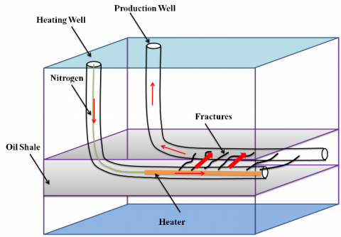
Oil shale, as a very tight sedimentary rock, has ultra-low porosity and permeability. Without reservoir modification, in-situ pyrolysis needs an excessively long heating cycle, if the oil shale formation is purely heated by heat transfer. Hence, it is of great necessity to modify the oil shale via hydraulic fracturing. The horizontal wells can be set up as one heating (H) well and one or several production (P) wells; the horizontal sections of the two kinds of wells can be extended over a long distance within the oil shale formation. The well deployment is illustrated in Figure 1. Then, the horizontal sections of the two kinds of wells need to be connected by hydraulic fracturing. During the fracturing, the fracturing fluid carries high-temperature resistant ceramsite proppant into the generated fractures, supporting the fractures and preventing them from closing. The resulting cracks not only increase the heating contact area of the oil shale formation, but also provide a channel for the generated shale oil to flow to the production well(s).
Figure 1. Principle of in-situ pyrolysis technology for oil shale
2.2 Heating technology for in-situ pyrolysis
Convection heating of oil shale with high-temperature heat carrier is an efficient way to heat oil shale in situ. After being injected from the heating well, the heat carrier transfers heat to the oil shale by convective heating, as it flows through the fractures induced by hydraulic fracturing. The heat will propagate to the inside of the oil shale via heat conduction. The high-temperature heat carrier will also enter the connected fractures generated during oil shale pyrolysis to heat the oil shale. Meanwhile, the heat carrier will carry the generated shale oil gas flow to the production well, and get pumped out via that well. After the separation of shale oil and gas, the heat carrier can be injected into the heating well again to realize cyclic use.
With relatively stable properties, nitrogen is a preferred choice as the heat carrier for heating oil shale. During the heating, such a heat carrier will not react with shale oil. In addition, nitrogen can be directed separated from the air, making the heat carrier easy to acquire. Nevertheless, if nitrogen is heated on the surface before being injected into the heating well, the temperature of the high-temperature nitrogen will be greatly reduced as it flows down to the bottom of the well. Then, it will be unable to effectively heat the oil shale. Therefore, a heater needs to be deployed in the horizontal well section of the heating well; normal temperature nitrogen is injected on the surface, and heated to high temperature by the heater. Then, the high-temperature nitrogen will enter the fractures of the oil shale generated by hydraulic fracturing to heat the oil shale. Figure 1 explains the principle of in-situ pyrolysis technology for oil shale with horizontal well fracturing and nitrogen injection.
To sum up, this paper develops a feasible, efficient, and safe in-situ pyrolysis technology for oil shale, which drills horizontal wells to the shale oil formation, connects the horizontal well sections via hydraulic fracturing, injects normal temperature nitrogen from the surface, heats the nitrogen in the horizontal section of the heating well, and directly uses the heated nitrogen for convective heating of the oil shale.
3.1 Mathematical model of in-situ pyrolysis of oil shale
During the flow in the fractures induced by hydraulic fracturing, the high-temperature nitrogen transfers its heat to the oil shale on the way. This process is a typical example of heat convection. Through heat convection, oil shale around each fracture is heated first. Then, the heat is gradually transferred from hot oil shale to the relatively cold rock mass deeper in the formation. Overall, the temperature of the entire oil shale formation slowly increases from the fractures to the inside. In this process, the heat is transferred within the solid oil shale. This is a process of heat conduction.
During the heating, the governing equation for the temperature field of oil shale can be derived from the momentum equation, continuity equation, and energy equation:
$\lambda \nabla^{2} T=\rho c+Q(x, y, z)$ (1)
The initial conditions are:
$T(x, y, z, 0)=T_{0}$ (2)
The boundary conditions are:
$\left.T\right|_{\Gamma 1}=T_{W}(x, y, z, t) \Gamma \in \Gamma 1$ (3)
$\left.\lambda \frac{\partial T}{\partial n}\right|_{\mathbb{2}}=q(x, y, z, t) \Gamma \in \Gamma 2$ (4)
$\left.\lambda \frac{\partial T}{\partial n}\right|_{\Gamma 3}=h\left(T_{2}-T\right) \Gamma \in \Gamma 3$ (5)
The governing equation, initial conditions, and boundary conditions for the temperature field of oil shale constitute the non-steady state mathematical model of the heat transfer for the in-situ pyrolysis of oil shale.where, T is the temperature of oil shale formation; t is time; λ is the coefficient of heat conduction for oil shale; c is the specific heat conductivity of oil shale; Q is the source sink term; T0 is the initial temperature of oil shale; Tw is the wall temperature; T2 is the fluid temperature on the boundary; q is the fluid density on the boundary; h is the heat transfer coefficient of the boundary; Γ is all the boundary conditions of the control body.
3.2 Physical model of in-situ pyrolysis of oil shale
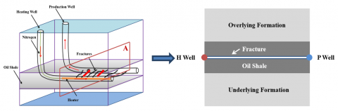
It is assumed that a connected fracture is formed under hydraulic fracturing between two horizontal well sections, which is filled with proppant and good at flow conduction. This fracture provides a channel for the high-temperature nitrogen, after being heated by the heater in the horizontal section of the heating well, to flow from the heating well to the production well. Under this assumption, the physical model of in-situ pyrolysis of oil shale can be simplified as a connecting fracture within a rectangular oil shale.
Suppose the horizontal section of each well is 100m long; the horizontal sections of the two wells are separated by 50m; the oil shale formation is 4m thick; the formations above the roof and below the floor of oil shale is 3m thick each; the connecting fracture is 1cm tall. Taking Profile A of the horizontal sections as the object and without considering the proppant in the fracture, the physical model of in-situ pyrolysis of oil shale can be established as shown in Figure 2.
Figure 2. Physical model of in-situ pyrolysis of oil shale
4.1 Basic physical parameters
The background parameters of numerical simulation are the basic physical parameters of the oil shale formation and its overlying and underlying formations in Nong’an County, Jilin Province, China. The measured basic physical parameters of Nong’an oil shale are recorded in Table 1. The numerical simulation does not consider the anisotropy of thermal conductivity coefficients and specific heat capacities of the oil shale and its overlying/underlying formations.
Table 1. Basic physical parameters of Nong’an oil shale
|
|
Oil content/% |
Density/(kg/m3) |
Heat conductivity coefficient/(w/m·℃) |
Specific heat capacity/(J/kg·℃) |
|
Oil shale |
6.33 |
1,722 |
1.03 |
1,905 |
|
Overlying/underlying formations |
/ |
1,650 |
0.91 |
1,858 |
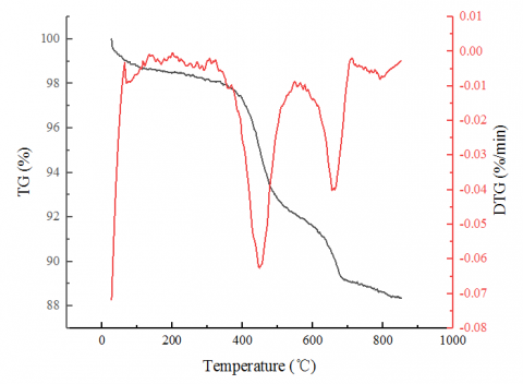
The thermogravimetric test of Nong’an oil shale was conducted at the heating rate of 10℃/min. During the test, high purity nitrogen was adopted as the pyrolysis carrier gas, with a flow rate of 60mL/min. From the pyrolysis loss curves (Figure 3), it can be seen that the pyrolysis loss took place in three stages. When the temperature was below 200℃, the weight loss is primarily the evaporation of the water vapor in the oil shale. When the temperature was within 300℃-500℃, the weight loss is primarily the pyrolysis of organic components in the oil shale. When the temperature was within 600℃-700℃, the weight loss is primarily the mineral decomposition under high temperature. The weight loss of oil shale mostly occurred in the temperature range of 350℃-450℃, i.e., the second stage. In that stage, kerogen, the organic component of oil shale, was converted into shale oil and gas in masses. Therefore, during numerical simulation, the effective pyrolysis zone was defined as the area above the temperature of 400℃, that is, the oil shale was considered as pyrolyzed, when its temperature reached to 400℃.
Figure 3. TG and DTG curves of oil shale
Note: TG and DTG stand for thermogravimetry and differential thermogravimetry, respectively.
The high-temperature nitrogen was supplied by injecting normal temperature nitrogen from the surface and heating the gas by the heater at the bottom of the well. During the numerical simulation, the temperature of the heated nitrogen was set to 600℃, the injection flow of nitrogen was set to 1,000Nm³/h, and the initial temperature of oil shale formation was set to 25℃.
4.2 Results analysis
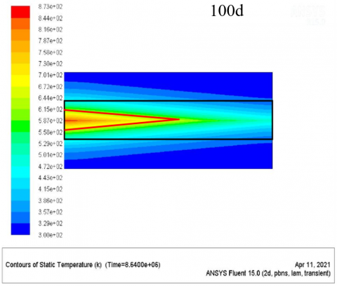
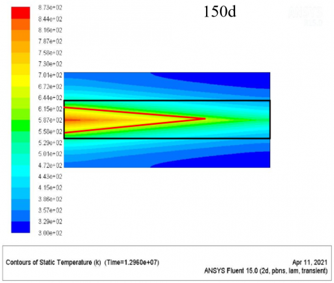
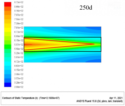
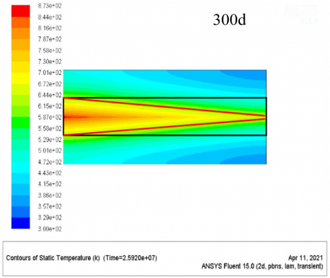
Figure 4. Temperature distribution of oil shale formation at different time into the heating process (oil shale formation in the black boxes, and effective pyrolysis zone in the red boxes)
The in-situ pyrolysis of oil shale was simulated on Ansys Fluent. Figure 4 is the images of temperature distribution of oil shale formation at different time into the heating process. The simulation results show that, with the extension of heating time, the oil shale temperature increased from the heating well to production well, and the heat was continuously transferred via the connected fracture to the overlying and underlying formations.
Figure 5. Proportion of effective pyrolysis zone in the cross-sectional area of oil shale formation at different time into the heating process
Figure 5 presents the proportion of effective pyrolysis zone (i.e., the area hotter than 400℃) in the cross-sectional area of oil shale formation at different time into the heating process. With the elapse of time, the proportion of effective pyrolysis zone gradually increased, but at a decreasing rate. The main reason is that the heat diffuses to the overlying and underlying formations, and the heat exchange reduces with the rising wall temperature of the fracture.
From Figures 4 and 5, it can be inferred that, after 300d of heating, the effective pyrolysis zone took up more than 50% of the cross-sectional area of oil shale formation. However, the temperature distribution was uneven within the formation. The oil shale near the heating well was hotter than 550℃, and lots of heat had diffused to the overlaying and underlying formations. On the contrary, the effective pyrolysis zone was rather thin in the oil shale around the production well. Thus, the overall heating effect is not satisfactory.
To improve the heating efficiency, a rotational heating scheme was designed. The nitrogen injection and heating process was divided into two stages. The first stage adopts the above nitrogen injection and heating technology. In the second stage, the heating well and production well were reversed, and the heater was relocated to the original production well (the new heating well). That is, nitrogen was injected from the original production well and extracted from the original heating well.
Without changing the total heating time (300d) and relevant parameters of nitrogen injection and heating, simulated the temperature field distribution under the new scheme: the nitrogen was injected and heated from the heating well for 50d, 100d, 150d, 200d, and 250d, respectively, to complete the first stage; then, the nitrogen was injected from the original production well to kick off the second stage of heating.
Taking the first stage of 150d for example, Figure 6(a) shows the oil shale temperature distribution at the end of the first stage of heating, with the area hotter than 400℃ being outlined; Figure 6(b) shows the oil shale temperature distribution at the end of the second stage of heating, with the area hotter than 400℃ being outlined; Figure 6(c) shows the effective pyrolysis zone superimposed from the two outlined areas.
Figure 6. Oil shale temperature distribution and effective pyrolysis zone under the new scheme (oil shale formation in the black boxes, and effective pyrolysis zone in the red boxes)
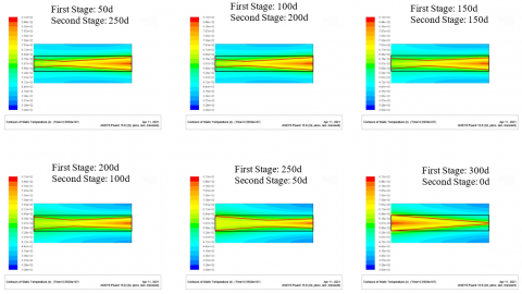
Similarly, the authors obtained the oil shale temperature distribution and effective pyrolysis zone under the new scheme with a total heating time of 300d (Figure 7). Figure 8 presents how the proportion of effective pyrolysis zone in the cross-sectional area and its maximum thickness change with the first stage heating time.
Figure 7. Effective pyrolysis zone under the new scheme with different heating time in each stage (oil shale formation in the black boxes, and effective pyrolysis zone in the red boxes)
Figure 8. Proportion of effective pyrolysis zone in the cross-sectional area and its maximum thickness at different first stage heating time
As shown in Figure 8, the proportion of effective pyrolysis zone first increased and then declined with the extension of first stage heating time. The proportion reached the maximum of 57%, when the first stage heating lasted 250d and the second stage heating lasted 50d. Referring to Figure 7, the oil shale formation saw the most uniform distribution of temperature under this heating model; the areas outside the effective pyrolysis zone also achieved a relatively high temperature. Therefore, the heating effect was optimized, and the energy was utilized in the most effective way.
The maximum thickness of effective pyrolysis zone first decreased and then increased with the extension of heating time in the first phase. The thickest effective pyrolysis zone was obtained by heating the nitrogen gas for 300d in the heating well. However, under this heating model, the pyrolysis zone mainly concentrated on one side of the heating well, leaving a thin pyrolysis zone on the side of the production well; this heating model did not maximize the effective pyrolysis zone, nor generate the most oil and gas products. The effective pyrolysis zone was maximized when the first stage of heating lasted 250d and the second stage of heating lasted 50d; in this case, the maximum thickness of that zone was 3.72m, no greater than the thickness of the oil shale formation.
The main reason is that, when the first stage of heating is too long, the heat extends deep from Well H to Well P. The oil shale around Well H is excessively hot, reaching 580℃ and above. The heat is transferred from the oil shale to the overlying and underlying formations continuously. In this case, the temperature is not uniformly distributed in the oil shale formation, the effective pyrolysis zone is not large, and the energy utilization remains low. When the first stage of heating is relatively short, only a limited range of formation around Well H is heated, and the heat transfer is within a limited height. Under the new scheme, as it flows from Well P to Well H, the high-temperature nitrogen loses much of its heat and gradually cools down. Once it reaches the formation around Well H, its temperature is already lower than the wall temperature of the fracture. Then, the gas actually cools down the oil shale at Well H. Although the area around the crack has been fully pyrolyzed in the first stage, the cooling effect suppresses the heating of the oil shale that has not been pyrolyzed around Well H in the first stage. That is why the effectively pyrolyzed zone is not large in the oil shale formation. The suppressive effect is not obvious, when the first stage of heating lasts long (200d or 250d).
(1) This paper proposes a novel in-situ pyrolysis technology for oil shale, which implements hydraulic fracturing, injects nitrogen via heating well, and heating the nitrogen at the bottom, based on horizontal wells. The implementation flow of the technology was introduced in details.
(2) If the oil shale is heated in situ purely by injecting nitrogen from the heating well and extracting it from the production well, the proportion of effective pyrolysis zone of oil shale increases slowly, the temperature distribution is uneven in the oil shale layer, and the heating effect is not satisfactory.
(3) After a while of heating, the production well and heating well are reversed, that is, injecting nitrogen from the original heating well and heating it for 250d, and then injecting nitrogen from the original production well and heating it for 50d. After heating the oil shale for a total of 300d, the effective pyrolysis zone can be maximized, and the temperature distribution can be uniform throughout the oil shale formation. Under this scheme, 57% of the cross-sectional area of the oil shale formation can be heated to above 400℃, realizing an effective heating effect.
This work was funded by Special Scientific Research Project of Education Department of Shaanxi Province, China (Grant No.: 19JK0538).
[1] Zhao, X., Zhang, X., Liu, Z., Lu, Z., Liu, Q. (2017). Organic matter in Yilan oil shale: characterization and pyrolysis with or without inorganic minerals. Energy & Fuels, 31(4): 3784-3792. https://doi.org/10.1021/acs.energyfuels.6b03404
[2] Han, X., Kulaots, I., Jiang, X., Suuberg, E.M. (2014). Review of oil shale semicoke and its combustion utilization. Fuel, 126: 143-161. https://doi.org/10.1016/j.fuel.2014.02.045
[3] Qian, J. (2008). Recent oil shale activities in China. Oil Shale, 25(4): 487-489.
[4] Dyni, J.R. (2006). Geology and resources of some world oil-shale deposits. 20: 193-252.
[5] Liu, Z., Meng, Q., Dong, Q., Zhu, J., Guo, W., Ye, S., Jia, J. (2017). Characteristics and resource potential of oil shale in China. Oil Shale, 34(1): 15-41. https://doi.org/10.3176/oil.2017.1.02
[6] Na, J.G., Im, C.H., Chung, S.H., Lee, K.B. (2012). Effect of oil shale retorting temperature on shale oil yield and properties. Fuel, 95: 131-135. https://doi.org/10.1016/j.fuel.2011.11.029
[7] Zhu, G., Zhang, B., Zhao, P., Duan, C., Zhao, Y., Zhang, Z., Rao, Z. (2019). Upgrading low-quality oil shale using high-density gas-solid fluidized bed. Fuel, 252: 666-674. https://doi.org/10.1016/j.fuel.2019.03.140
[8] Kang, Z., Zhao, Y., Yang, D. (2020). Review of oil shale in-situ conversion technology. Applied Energy, 269: 115121. https://doi.org/10.1016/j.apenergy.2020.115121
[9] Zhu, J., Yi, L., Yang, Z., Li, X. (2021). Numerical simulation on the in situ upgrading of oil shale reservoir under microwave heating. Fuel, 287: 119553. https://doi.org/10.1016/j.fuel.2020.119553
[10] Sun, Y., Bai, F., Liu, B., Liu, Y., Guo, M., Guo, W., Yang, Y. (2014). Characterization of the oil shale products derived via topochemical reaction method. Fuel, 115: 338-346. https://doi.org/10.1016/j.fuel.2013.07.029
[11] Sun, Y.H., Deng, S.H., Guo, W., Li, Q., Liu, S.C., Jia, R. (2017). In situ pyrolysis technology and pilot test project of oil shale. The Drilling Engineering Symposium of Drilling Engineering Professional Committee of China Coal Society.
[12] Ma, J.X., Xue, L.F., Zhao, J.M., Bai, F.T. (2019). Numerical simulation and design optimization of temperature field of oil shale in situ pyrolysis and exploitation. Science Technology and Engineering, 19(5): 94-103.
[13] Kang, Z., Zhao, Y., Yang, D., Tian, L., Li, X. (2020). A pilot investigation of pyrolysis from oil and gas extraction from oil shale by in-situ superheated steam injection. Journal of Petroleum Science and Engineering, 186: 106785. https://doi.org/10.1016/j.petrol.2019.106785
[14] Wang, Z., Deng, S., Gu, Q., Cui, X., Zhang, Y., Wang, H. (2014). Subcritical water extraction of Huadian oil shale under isothermal condition and pyrolysate analysis. Energy & Fuels, 28(4): 2305-2313. https://doi.org/10.1021/ef5000062
[15] Brandt, A.R. (2008). Converting oil shale to liquid fuels: Energy inputs and greenhouse gas emissions of the Shell in situ conversion process. Environmental Science & Technology, 42(19): 7489-7495. https://doi.org/10.1021/es800531f
[16] Zheng, D., Li, S., Ma, G., Wang, H. (2012). Autoclave pyrolysis experiments of Chinese Liushuhe oil shale to simulate in-situ underground thermal conversion. Oil Shale, 29(2): 103. https://doi.org/10.3176/OIL.2012.2.02
[17] Ryan, R.C., Fowler, T.D., Beer, G.L., Nair, V. (2010). Shell’s in situ conversion process− from laboratory to field pilots. In Oil Shale: A Solution to the Liquid Fuel Dilemma, 1032: 161-183. https://doi.org/10.1021/bk-2010-1032.ch009
[18] Fei, Y., Marshall, M., Jackson, W.R., Qi, Y., Auxilio, A.R., Chaffee, A.L., Cassidy, P.J. (2018). Long-time-period, low-temperature reactions of Green River oil shale. Energy & Fuels, 32(4): 4808-4822. https://doi.org/10.1021/acs.energyfuels.8b00019
[19] Kang, Z., Zhao, Y., Yang, D., Tian, L., Li, X. (2020). A pilot investigation of pyrolysis from oil and gas extraction from oil shale by in-situ superheated steam injection. Journal of Petroleum Science and Engineering, 186: 106785. https://doi.org/10.1016/j.petrol.2019.106785
[20] Wang, L., Yang, D., Zhao, J., Zhao, Y., Kang, Z. (2018). Changes in oil shale characteristics during simulated in-situ pyrolysis in superheated steam. Oil Shale, 35(3): 230-241. https://doi.org/10.3176/oil.2018.3.03
[21] Wang, L., Zhao, Y., Yang, D., Kang, Z., Zhao, J. (2019). Effect of pyrolysis on oil shale using superheated steam: A case study on the Fushun oil shale, China. Fuel, 253: 1490-1498. https://doi.org/10.1016/j.fuel.2019.05.134