Fazlay Rubbi* | Khairul Habib | Mehedi Tusar | Likhan Das | Md. Tauhidur Rahman
© 2020 IIETA. This article is published by IIETA and is licensed under the CC BY 4.0 license (http://creativecommons.org/licenses/by/4.0/).
OPEN ACCESS
Heat transfer enhancement of heat exchangers is an important matter of concern to achieve more effective thermal energy conversion systems. The use of modified twisted tape (TT) inserts as passive technique of heat transfer augmentation are effective way to improve heat transfer. In this study, a numerical analysis is performed to investigate the heat transfer performance enhancement and flow behavior in a circular pipe using TT insert fitted with a hemispherical extruded surface (HES). The study is carried out for the turbulent flow regime (4000≤Re≤10000) at a twist ratio of 4.0 using ANSYS FLUENT. A flow domain is designed and mathematically modeled applying boundary conditions and using governing equations for turbulent model. The plain tube data is validated with established correlations. The achieved numerical results reveal that for TT fitted with HES leads to increment in heat transfer rate up to 69.4% compared to plain tube due to effective swirl flow and better mixing caused by the insert. Corresponding increase in friction factor is found relative to plain tube. The impact on the thermal performance factor has obtained a maximum of 1.24 at constant pumping power for Reynold number 4000.
hemispherical extruded surface, twisted tape, turbulent flow, friction factor, thermal performance factor
Several heat transfer intensification methods are generally employed to raise the thermal output of heat exchanger because of its extensive applications in industrial fields, for instance, refrigeration and air-conditioning, chemical manufacturing, solar collectors, electronic device cooling, and power generation. Depending on the usage of external power, various active and passive approaches are applied to intensify the convective heat transfer performance of many heat exchangers in the past few decades. Compared to active methods, passive methods are popular among engineers and researchers as passive methods do not depend on any external power sources. Among passive methods, the addition of inserts inside the heat exchanger tube to produce swirl flow to obtain higher heat transfer performance is reported very useful. Twisted tape, helical screwed tape, spiral spring, conical strip, and coiled-wire are the examples of most frequently studied inserts in the literature and proposed for further investigation with modification [1-5]. The function of these inserts is to create vortex by generating swirl flow, which reduces thermal boundary thickness and causes angular acceleration to the flow to enhance flow behavior and heat transfer characteristics. Twisted tapes are effective swirl generators due to their optimum twisted-shaped design, which can produce vortex flow to improve boundary layer perturbation and better blending between the central region and boundary regions of the tube to boost flow turbulence and thermal performance of the systems [6]. However, a significant pressure drop is caused by the addition of twisted tapes into the fluid flow. Therefore, the optimal design of the twisted tape inserts should be established to achieve maximum heat transfer rate with minimal frictional resistance through the pipe integrated with twisted tapes.
In recent years, many experimental studies along with numerical simulations have been performed by researchers worldwide to study the flow mechanism and heat transfer phenomena of pipe flow integrated with both conventional and modified twisted tapes. Eiamsa-ard et al. [7] observed the impact of full-length and equally spread out twisted tape inserts on the coefficient of heat transfer and frictional properties through a dual-pipe heat exchanger and stated the rise in convective heat transfer performance at smaller twist ratio with a consequence of the increase in friction factor. Furthermore, they concluded that the heat transfer rate was more prominent at lower space ratio as well as twist ratio but with higher value friction factor. Murugesan et al. [8] investigated flow behavior and thermal performance using reformed twisted tape inserts with V-cut. The achieved results with V-cut supplement exhibited 2.46 and 5.82 times greater Nusselt number and resistance caused by friction than a smooth tube, respectively. Besides, the depth ratio of V-cut performed more heat transfer than the width ratio of the V-cut. Tamna et al. [9] experimentally studied performance intensification using ribbed twisted tapes. The results revealed significant improvement in Nusselt number and thermal performance of tubular heat exchanger compared to TT with no rib. Eiamsa-ard et al. [10] used helically designed twisted tapes as vortex and turbulence generator and reported heat transfer escalation for turbulent flow (6000<Re<20000). The obtained findings reveal that the coil-shaped tapes yielded a more effective performance factor than regular helical tape inserts. Furthermore, heat transfer rate and flow resistance went up with reducing twist ratio, whereas; the thermal performance showed the opposite movement.
Hasanpour et al. [11] experimentally and analytically examined performance intensification and pressure drop through a wavy pipe heat exchanger with conventional and modified (U-cut, perforated and V-cut) twisted tapes in turbulent regime (Reynold number, 5000 to 15000) at three twist ratios. The outcomes depicted maximum heat transfer performance for modified V-cut based twisted tapes while the least pressure drop attributed to modified perforated type twisted tape inserts. Moreover, maximum performance factor 1.50 was recorded for V-cut inserts at the lowest twist ratio. All the results are found to be in accord with numerically predicted results with less than 2% deviation. Khoshvaght-Aliabadi et al. [12] revealed that agitated vessel heat exchanger fitted with spiky aluminum twisted tape inserts resulted in approximately 67% increased heat transfer coefficient than a regular plain pipe. Tusar et al. [13] numerically studied heat transfer augmentation and flow characteristics of airflow through a tube combined with twisted tape inserts for turbulent flow regime. Their findings showed that the maximum increment of Nusselt number and flow resistance is 62% and 245%, respectively. Besides, twisted tapes yielded better heat transfer at the smallest twist ratio and lower Reynolds number. In another numerical investigation [3] observed the effect of helical screw tapes with a 1.92 twist ratio for laminar flow. They found maximum of 2.6 times improved Nusselt number for helical screw tapes while frictional resistance increased by 8 times compared to the smooth pipe. Nakhchi and Esfahani [14] presented a numerical study of heat transfer growth for tube heat exchanger integrated with dual V-cut twisted tape inserts. The obtained results describe a maximum 117.4% augmentation of heat transfer rate with V-cut twisted tapes than regular twisted tapes and more effective turbulent swirl flow generation due to intense collision. Also, larger cuts found to produce higher performance factors than a parallel increase in pressure drop at 5000< Re <15000. Nakhchi and Esfahani [15] inspected thermal-hydraulic behaviors of a circular tube heat exchanger fitted with rectangular single-cut and double-cut twisted tape inserts in turbulent flow regime. They revealed double-cut twisted tape yield higher turbulence than single-cut tape, and a maximum 33.26% increment of Nusselt number was reported for change in cut ratio from 0.25 to 0.75. Saysroy and Eiamsa-ard [16] analyzed flow behavior and performance intensification using multi-channel twisted through circular tube tapes. Their findings showed that the Nusselt number of the flow increase at higher channel number and lesser twist ratio for low to high Reynolds numbers.
The above discussed literatures describe that the heat transfer intensification using modified twisted tape inserts is an efficient passive technique to obtain better heat transfer augmentation due to additional escalation in swirl flow generation and turbulence. Among various modified TT, the ones with modified designs (ribs and cuts) perform better heat transfer enhancement due to additional effective swirl flow formed by the ribbed surfaces or cuts and improves the turbulent intensity of the fluid flow. However, the effect of hemispherical extruded surface (HES) fitted with TT insert through a tube has never been studied to date. This inspired the present study to perform a numerical analysis using the HES integrated with TT insert to investigate the heat transfer improvement in a circular pipe flow in the turbulent regime. In addition, this analysis could be useful for better understanding of heat transfer improvement employing modified TT inserts and to design advanced heat exchanges with better efficiency.
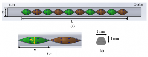
The schematic diagram in Figure 1 shows the geometry of the designed fluid domain integrated with TT insert fitted with HES. The domain has a length of 500 mm and a diameter (D) of 16 mm. The added twisted tape is 400 mm long (L) with pitch length (y) of 40 mm and width (w) of 10 mm. Therefore, the twist ratio (TR=y/w) is 4. Generally, several types of inserts implemented in convective heat transfer intensification uses twist ratio between 1 to 10. Promvonge et al. [17] investigated twist ratio 2.17-9.39 for double twisted tape in helical ribbed channel. Performance was better for higher twist ratio with high friction factor. Thianpong et al. [18] experimented twisted tape with twist ratio 3, 5, 7 in a dimpled tube. Results demonstrated better performance for lower twist ratios with relatively less friction factor than helical ribbed insert. Hence, a twist ratio in between the range is selected for optimum performance in this investigation. The insert is placed 50 mm apart from the inlet section and ends 50 mm before the outlet. Hemispherical extruded surfaces with 2 mm diameter and 1 mm height are fitted on the surface of the TT on both sides of the tape to intensify turbulence during the flow.
Figure 1. Schematic diagram of designed twisted tape insert fitted with a hemispherical extruded surface (a) full insert view, (b) geometry of TT (c) geometry of the hemispherical extruded surface
3.1 Governing equations
The numerical domain for the tube flow with twisted tape insert fitted with HES is established. Considering assumptions and boundary conditions stated in the next section, the fluid flow behavior and heat transfer characteristics are carried out with a set of differential governing equations. The governing equations are utilized for a three-dimensional model are stated below.
Continuity equation:
$\frac{\partial}{\partial x_{i}}\left(\rho u_{i}\right)=0$ (1)
Energy equation:
$\frac{\partial}{\partial x_{i}}\left[u_{i}(\rho E+P)\right]=\frac{\partial}{\partial x_{j}}\left[k_{e f f}\left(\frac{\partial}{\partial x_{j}}\right)\right]$ (2)
$E=h-\frac{P}{\rho}+\frac{u^{2}}{2}$ (3)
Momentum equation:
$\frac{\partial\left(\rho u_{i} u_{j}\right)}{\partial x_{j}}=-\frac{\partial p}{\partial x_{i}}$
$+\frac{\partial}{\partial x_{j}}\left[\mu\left(\frac{\partial u_{i}}{\partial x_{j}}+\frac{\partial u_{j}}{\partial x_{i}}-\frac{2}{3} \delta_{i j} \frac{\partial u_{k}}{\partial x_{k}}\right)\right]+\frac{\partial}{\partial x_{j}}\left(-\rho \bar{\acute{{u}_{l}}\acute u_{j}}\right)$ (4)
where, $-\rho \bar{\acute{{u}_{l}}\acute u_{j}}$ is the Reynold stresses, and it can be found from Boussinesq equations.
$-\rho \bar{\acute{{u}_{l}}\acute u_{j}}=\mu_{t}\left(\frac{\partial u_{i}}{\partial x_{j}}+\frac{\partial u_{j}}{\partial x_{i}}\right)-\frac{2}{3}\left(\rho k+u_{t} \frac{\partial u_{k}}{\partial x_{k}}\right) \delta_{i j}$ (5)
where, $\rho$ is the fluid density, $u_{i}$ is the velocity component at x_i, dynamic viscosity $\mu$, pressure P, fluctuating velocity component $\acute{u}$, and $u_{t}$ is the viscosity due to turbulence. $u_{t}$ can be defined as;
$u_{t}=\frac{\rho C_{\mu} k^{2}}{\varepsilon}$ (6)
where, turbulent kinetic energy $k=1 / 2 \bar{\acute{{u}_{l}}\acute u_{j}}$.
3.2 Boundary conditions
At the inlet flow domain, the velocity inlet state is applied with water enters at 300K temperature in correspondent velocity while the pressure outlet boundary condition is implemented at the outlet pipe section for all the simulations. The flow is three-dimensional, steady, turbulent, and incompressible. Pressure drop is calculated considering zero-gauge pressure at the outlet. Simulations were run for both bare tube and the integrated tube with twisted tapes at constant wall temperature condition. The constant heat flux standards are utilized to perform the simulation. Twisted tape insert fitted with hemispherical extruded surface immersed into water with adiabatic boundary condition; therefore, heat loss is negligible. No-slip boundary condition is considered for twisted tape surface and tube wall.
3.3 Data reduction
This research primarily focuses on the key parameters in heat transfer, such as heat transfer coefficient, flow behavior, Nusselt number (Nu), and the thermal performance factor of the system.
The heat transfer coefficient is defined by
$h=\frac{Q}{A \cdot \Delta T}$ (7)
The Nusselt number is calculated by
$N u=\frac{h d}{k}$ (8)
The average value of Nu can be determined by
$N u_{a v g}=\frac{1}{L} \int N u(x) \partial x$ (9)
The flow behavior (friction factor) can be defined by
$f=\frac{2 D}{L} \frac{\Delta p}{\rho u^{2}}$ (10)
The thermal performance factor (η) is evaluated with the following equation:
$\eta=\frac{\frac{N u}{N u_{p}}}{\left(\frac{f}{f p}\right)^{\frac{1}{3}}}$ (11)
where, $N u_{p}$ and $f_{p}$ is the Nusselt number and friction factor for a plain tube.
4.1 Numerical method and grid sensitivity analysis
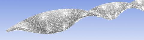
Heat transfer characteristics and the flow behavior of the turbulent flow through a tube with twisted tape inserts fitted with the hemispherical extruded surface are predicted by solving relevant governing equations. Navier-Stokes equation is used to determine the developed flow motion of the working fluid. To resolve the Navier-Stokes equations Semi-Implicit Method for Pressure-Linked Equations (SIMPLE) algorithm is implicated, whereas the second-order upwind technique is used to convert these equations. The numerical study is performed by considering the convergence below 10-7 for residual energy and below 10-4 for moment equations. Commercial ANSYS software is used to perform the numerical investigation. The properties of working fluid (water) are provided in Table 1. The geometry of insert fitted tube is complex in nature. Therefore, unstructured meshing is used for better mesh quality. It produces hexahedral elements in relatively simple geometry and tetrahedral, prism mesh in interfaces, where the geometry is complex and boundary changes rapidly. Figure 2 depicts the discretized insert domain of the developed model. Dense mesh was generated in the vicinity of HES to capture the physics perfectly. Inflation layers were implemented on heat flux surface and insert wall to produce multiple element layers in thin area as flow phenomena changes rapidly in boundary layer.
Figure 2. Mesh generation for the TT insert fitted with HES
Table 1. Properties of working fluid (water)
|
Properties |
Value |
|
Thermal conductivity, k |
0.6 W/m-k |
|
Specific heat capacity, CP |
4180 J/kg-k |
|
Prandtl number, Pr |
7 |
|
Density, ρ |
998 Kg/m3 |
|
Dynamic viscosity, µ |
1.003×10⁻³ Kg/m-s |
Table 2. Grid sensitivity test
|
Mash size (elements) |
Re |
Outlet temperature (K) |
Error (%) |
|
869054 |
7000 |
300.12 |
-- |
|
1107129 |
303.36 |
1.07 |
|
|
1418576 |
305.17 |
0.59 |
|
|
1719321 |
306.60 |
0.46 |
|
|
2123479 |
306.84 |
0.07 |
4.2 Validation for plain tube
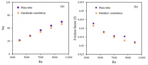
To assess the accuracy and precision of the present numerical study, the friction factor and Nusselt number results for the plain tube are validated with the Petukhov correlation and Gnielinski correlation [19, 20] respectively in Figure 3 (a&b). As found, Nu and friction factor results of plain tube are within ±8.21 and ±6.66% of those from the respective correlations. From the stated results, it can be concluded that this numerical study provides satisfactory simulation accuracy as the results are in good agreement with the mentioned standard correlations.
Figure 3. Validation of plain tube numerical data with respect to Reynolds number (a) Nusselt number (b) Friction factor
5.1 Heat transfer characteristics
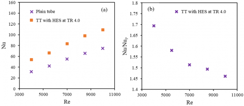
As the constant heat flux condition is applied for both plain tube (PT) and TT with HES, an equal amount of heat is maintained for both cases. For PT, the fluid velocity is near zero at the adjacent region of the boundary due to no-slip condition and results in less heat transfer rate. Whereas for TT fitted with HES, velocity enhances due to intensification in swirl flow with the integration of TT in the plain tube and results in significant improvement in heat transfer rate (Nu). Figure 4 represents a rise in Nusselt number (Nu) with the increase in Reynolds number (Re) in the pipe flow with TT fitted HES. Therefore, noteworthy enhancement is observed in the heat transfer rate with increasing Re from 4000 to 10000 due to escalation in swirl flow intensity and heat convection in the considered turbulent flow regime. The addition of TT fitted with HES resulted in up to 69.4% enhanced Nu than the bare tube alone. However, $N u / N u_{p}$ tends to decrease at higher Re from Figure 4(b). This is attributed to the thicker boundary layer at lower value of Re.
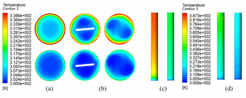
Figure 5 (a and b) demonstrate the temperature profile for Re (4000 to 10000) at the outlet for plain tube and the TT fitted with HES, respectively. Similarly, Figure 5 (c and d) show the wall temperature gradient for without insert and with insert. The figures describe that for constant heat flux condition, boundary wall temperature and outlet temperature is higher for PT at both Nusselt numbers because of less velocity and heat dissipation capacity. But for TT fitted with HES, effective heat distribution and intense swirl generation provide less temperature difference between surface and the outlet, which results in improved heat transfer characteristics of TT fitted with HES than PT.
5.2 Friction factor characteristics
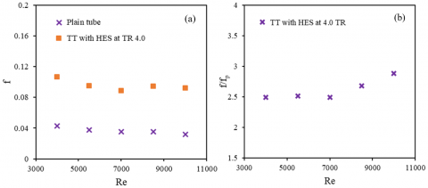
Figure 6 depicts variation fluid flow characteristic (friction factor) for PT and TT with HES against Re. For the considered range of the Re, friction factor tends to decrease with Re, whereas f/fp increases at a higher value of Re. Although significant intensification is found using TT fitted HES with the PT, friction factor elevated correspondingly due to the presence of the TT fitted with HES. The friction factor is directly related to the pressure drop of a system therefore, high pumping power is required to run the system at a high friction factor.
At TR 4.0, friction factor escalated 149-188% for TT fitted HES compared to the PT. This is due to the resistance to the flow and turbulence caused by the higher velocity of the fluid flow. The results are in accord with relevant studies with twisted tapes [10, 21, 22].
Figure 4. Characteristics of Nusselt number against Reynolds number (a) enhancement of Nu for TT with HES at TR 4.0 (b) enhancement ratio for TT with HES to the plain tube
Figure 5. Temperature profile at Re=4000 and Re=10000 for (a) Plain tube outlet (b) TT outlet and tube outlet with insert (left to right) (c) Pipe wall alone (d) Pipe wall with TT fitted with HES
Figure 6. Friction factor characteristics against Reynolds number (a) rise in friction factor using TT fitted with HES (b) ratio of friction factors
5.3 Thermal performance analysis
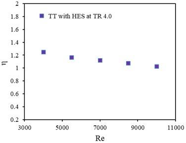
Figure 7 demonstrates the effect of Reynolds number on thermal performance factor at constant pumping power of the system. As stated by previous studies [23, 24].
Figure 7. Thermal performance factor against Reynolds number
Performance enhancement using turbulators (t) in a plain tube (p) at constant pumping power can be determined by the following equations:
For constant pumping power:
$(Q \Delta P)_{p}=(Q \Delta P)_{t}$ (12)
From the relationship between friction factor and Reynolds number:
$\left(f R e^{3}\right)_{p}=\left(f R e^{3}\right)_{t}$ (13)
$R e_{t}=R e_{p}\left(\frac{f_{p}}{f_{t}}\right)$ (14)
According to the definition of thermal performance factor:
$\eta=\frac{\frac{N u}{N u_{p}}}{\left(\frac{f}{f_{p}}\right)^{\frac{1}{3}}}$ (15)
The relationship implies that the value of the thermal enhancement factor remained higher than unity for considered Re number range. Therefore, TT fitted with HES has a positive impact on heat transfer enhancement of the system. Results depicted that η is higher at lower Reynolds number, being maximum 1.24 at Re 4000.
A numerical study on fluid flow characteristics of turbulent flow through a tube with twisted tape inserts fitted with hemispherical extruded surface is performed at twist ratio (TR) 4.0 using ANSYS, a commercial software. The key findings of the study are as follows:
(1) Reduction of wall surface temperature and intensification of swirl flow with an integrated arrangement of PT with TT fitted with HES lead to convection improved heat transfer behaviour of the system with the inserted TT instead of PT.
(2) Heat transfer rate (Nu) augmented significantly against Reynolds number (Re) with the addition of TT fitted with HES at TR 4.0. The maximum enhancement achieved 69.4% compared to the plain tube.
(3) Fluid flow characteristics for TT fitted with HES evaluated in terms of friction factor, which tends to increase correspondingly with increasing Re up to 188% than PT.
(4) The thermal performance factor is obtained higher than unity (ranged 1.02-1.24), indicate a positive impact on the system energy savings.
The performance achieved in the current study offered by HES fitted TT indicate potential aspect TT in terms of energy saving in thermal system. This study can provide theoretical direction for thermal design and production of heat exchanger tubes with TT fitted with HES. However, penalty in friction factor still remains a key challenge in the analysis of heat transfer augmentation with TT inserts. Hence, authors will continue their endeavor to analyze and design more effective inserts-based heat exchanger in their future researches in this field.
|
HES |
Hemispherical extruded surface |
|
TT |
Twisted tape |
|
Re |
Reynold number |
|
Nu |
Nusselt number |
|
Pr |
Prandlt number |
|
k |
Thermal conductivity, W/m-K |
|
cp |
Specific heat capacity, J/kg-K |
|
Q |
Heat flux, W/m2 |
|
h |
Convective heat transfer coefficient, W/m2.K |
|
L |
Length of the pipe, m |
|
D |
Pipe diameter, m |
|
y/w |
Twist ratio |
|
$\Delta T$ |
Temperature difference, K |
|
u |
Fluid velocity, m.s-1 |
|
f |
Friction factor |
|
$\Delta P$ |
Pressure drop |
|
Greek symbols |
|
|
ρ |
Fluid density, Kg/m3 |
|
µ |
Dynamic viscosity, Kg/m-s |
|
µt |
Viscosity due to turbulence, Kg/m-s |
|
η |
Thermal performance factor |
|
Subscripts |
|
|
p |
Plain tube |
|
t |
Turbulent |
[1] Zhang, C., Wang, D., Zhu, Y., Han, Y., Wu, J., Peng, X. (2015). Numerical study on heat transfer and flow characteristics of a tube fitted with double spiral spring. International Journal of Thermal Sciences, 94: 18-27. https://doi.org/10.1016/j.ijthermalsci.2015.02.001
[2] Bhuiya, M.M.K., Chowdhury, M.S.U., Ahamed, J.U., Azad, A.K. (2016). Heat transfer performance evaluation and prediction of correlation for turbulent flow through a tube with helical tape inserts at higher Reynolds number. Heat and Mass Transfer, 52(6): 1219-1230. https://doi.org/10.1007/s00231-015-1643-y
[3] Tusar, M., Ahmed, K., Bhuiya, M., Bhowmik, P., Rasul, M., Ashwath, N. (2019). CFD study of heat transfer enhancement and fluid flow characteristics of laminar flow through tube with helical screw tape insert. Energy Procedia, 160: 699-706. https://doi.org/10.1016/j.egypro.2019.02.190
[4] Pourramezan, M., Ajam, H. (2016). Modeling for thermal augmentation of turbulent flow in a circular tube fitted with twisted conical strip inserts. Applied Thermal Engineering, 105: 509-518. https://doi.org/10.1016/j.applthermaleng.2016.03.029
[5] Sharifi, K., Sabeti, M., Rafiei, M., Mohammadi, A.H., Shirazi, L. (2018). Computational fluid dynamics (CFD) technique to study the effects of helical wire inserts on heat transfer and pressure drop in a double pipe heat exchanger. Applied Thermal Engineering, 128: 898-910. https://doi.org/10.1016/j.applthermaleng.2017.08.146
[6] Nakhchi, M.E., Esfahani, J.A. (2019). Sensitivity analysis of a heat exchanger tube fitted with cross-cut twisted tape with alternate axis. Journal of Heat Transfer, 141(4): 041902. https://doi.org/10.1115/1.4042780
[7] Eiamsa-ard, S., Thianpong, C., Promvonge, P. (2006). Experimental investigation of heat transfer and flow friction in a circular tube fitted with regularly spaced twisted tape elements. International Communications in Heat and Mass Transfer, 33(10): 1225-1233. https://doi.org/10.1016/j.icheatmasstransfer.2006.08.002
[8] Murugesan, P., Mayilsamy, K., Suresh, S., Srinivasan, P.S.S. (2011). Heat transfer and pressure drop characteristics in a circular tube fitted with and without V-cut twisted tape insert. International Communications in Heat and Mass Transfer, 38(3): 329-334. https://doi.org/10.1016/j.icheatmasstransfer.2010.11.010
[9] Tamna, S., Kaewkohkiat, Y., Skullong, S., Promvonge, P. (2016). Heat transfer enhancement in tubular heat exchanger with double V-ribbed twisted-tapes. Case Studies in Thermal Engineering, 7: 14-24. https://doi.org/10.1016/j.csite.2016.01.002
[10] Eiamsa-ard, S., Yongsiri, K., Nanan, K., Thianpong, C. (2012). Heat transfer augmentation by helically twisted tapes as swirl and turbulence promoters. Chemical Engineering and Processing: Process Intensification, 60: 42-48. https://doi.org/10.1016/j.cep.2012.06.001
[11] Hasanpour, A., Farhadi, M., Sedighi, K. (2017). Intensification of heat exchangers performance by modified and optimized twisted tapes. Chemical Engineering and Processing - Process Intensification, 120: 276-285. https://doi.org/10.1016/j.cep.2017.07.026
[12] Khoshvaght-Aliabadi, M., Davoudi, S., Dibaei, M.H. (2018). Performance of agitated-vessel U tube heat exchanger using spiky twisted tapes and water based metallic nanofluids. Chemical Engineering Research and Design, 133: 26-39. https://doi.org/10.1016/j.cherd.2018.02.030
[13] Tusar, M., Noman, A., Islam, M., Yarlagadda, P., Salam, B. (2019). CFD study of heat transfer enhancement and fluid flow characteristics of turbulent flow through tube with twisted tape inserts. Energy Procedia, 160: 715-722. https://doi.org/10.1016/j.egypro.2019.02.188
[14] Nakhchi, M.E., Esfahani, J.A. (2019). Performance intensification of turbulent flow through heat exchanger tube using double V-cut twisted tape inserts. Chemical Engineering and Processing - Process Intensification, 141: 107533. https://doi.org/10.1016/j.cep.2019.107533
[15] Nakhchi, M.E., Esfahani, J.A. (2019). Numerical investigation of rectangular-cut twisted tape insert on performance improvement of heat exchangers. International Journal of Thermal Sciences, 138: 75-83. https://doi.org/10.1016/j.ijthermalsci.2018.12.039
[16] Saysroy, A., Eiamsa-ard, S. (2017). Enhancing convective heat transfer in laminar and turbulent flow regions using multi-channel twisted tape inserts. International Journal of Thermal Sciences, 121: 55-74. https://doi.org/10.1016/j.ijthermalsci.2017.07.002
[17] Promvonge, P., Pethkool, S., Pimsarn, M., Thianpong, C. (2012). Heat transfer augmentation in a helical-ribbed tube with double twisted tape inserts. International Communications in Heat and Mass Transfer, 39(7): 953-959. https://doi.org/10.1016/j.icheatmasstransfer.2012.05.015
[18] Thianpong, C., Eiamsa-ard, P., Wongcharee, K., Eiamsa-ard, S. (2009). Compound heat transfer enhancement of a dimpled tube with a twisted tape swirl generator. International Communications in Heat and Mass Transfer, 36(7): 698-704. https://doi.org/10.1016/j.icheatmasstransfer.2009.03.026
[19] Gnielinski, V. (1976). New equations for heat and mass transfer in turbulent pipe and channel flow. International Chemical Engineering, 16(2): 359-368. https://doi.org/10.1021/i360060a018
[20] Petukhov, B.S. (1970). Heat transfer and friction in turbulent pipe flow with variable physical properties. Advances in Heat Transfer, 6: 503-564. https://doi.org/10.1016/S0065-2717(08)70153-9
[21] Salam, B., Biswas, S., Saha, S., Bhuiya, M.M.K. (2013). Heat transfer enhancement in a tube using rectangular-cut twisted tape insert. Procedia Engineering, 56: 96-103. https://doi.org/10.1016/j.proeng.2013.03.094
[22] Piriyarungrod, N., Kumar, M., Thianpong, C., Pimsarn, M., Chuwattanakul, V., Eiamsa-ard, S. (2018). Intensification of thermo-hydraulic performance in heat exchanger tube inserted with multiple twisted-tapes. Applied Thermal Engineering, 136: 516-530. https://doi.org/10.1016/j.applthermaleng.2018.02.097
[23] Promvonge, P., Eiamsa-ard, S. (2007). Heat transfer augmentation in a circular tube using V-nozzle turbulator inserts and snail entry. Experimental Thermal and Fluid Science, 32(1): 332-340. https://doi.org/10.1016/j.expthermflusci.2007.04.010
[24] Eiamsa-ard, S., Wongcharee, K., Eiamsa-ard, P., Thianpong, C. (2010). Heat transfer enhancement in a tube using delta-winglet twisted tape inserts. Applied Thermal Engineering, 30(4): 310-318. https://doi.org/10.1016/j.applthermaleng.2009.09.006