Ahmed Youcef* | Rachid Saim
© 2019 IIETA. This article is published by IIETA and is licensed under the CC BY 4.0 license (http://creativecommons.org/licenses/by/4.0/).
OPEN ACCESS
In order to gain an understanding of the mechanism for increasing thermal performance in the shell side, two models of shell and tube heat exchangers are proposed in this study. Numerical investigations of the shell side fluid flow and heat transfer are performed using CFD FLUENT commercial software based on the k-ε model, the conservation equations of mass, momentum and energy are solved by the finite volume method. The results show that the fluid is completely affected by the baffles. The heat transfer coefficient and the pressure drop varies significantly in the case of the presence of the baffle as an increase from 1.86% and 21.67% successively, the total heat transfer rate increase by 1.11%. The velocity increases by 12% in the case without baffles and by 19% in the case with baffles.
heat exchanger, segmental baffle, CFD, thermo-hydraulic performance
The study of fluid flow in annular geometries is a great importance in industrial applications because it is the common design of the shell and tube heat exchangers.
Tube bundle heat exchangers are the most used in many applications, because more than 35% of the heat exchangers in the world are of this type because of their robust construction [1, 2]. A shell and tube heat exchanger with a 25% baffle cut were used in the study of Saffarian et al. [3]. Tubes of different cross-sections (circular, elliptical with an attack angle of 90° and elliptical with an attack angle of 0°) were studied. A combined model of a shell and tube heat exchanger with elliptical tubes with an attack angle of 90° and circular tubes was introduced. The effect of the location of tubes on heat transfer was investigated. It was shown that tubes located near the shell have a greater impact on heat transfer compared with tubes located in the center of the shell. Shell and tube heat exchangers with segmental baffles have been well developed and widely used [4], tubes and baffles being the main design elements that may affect the performance of the heat exchanger. Several techniques have been proposed to improve the heat transfer, the inclination or the variation of the geometrical parameters of the walls, the implementation of the baffles in the flow space. Several studies have been conducted to examine the performance of the system with baffles. The presence of obstacles favors turbulence and heat transfer and also allows a good distribution of the fluid flow [5-8]. Patankar and Sparrow [9] presented the concept of fully developed periodic flow. Kelkar and Patankar [10] prove that the number of Nusselt and the friction factor increase with the Reynolds number. Saim et al. [11] have studied the effects of space between the baffles on heat transfer and pressure drop, the results show, an increase in the number of Nussels with increasing Reynolds number, the regions of low and high pressure are associated with recirculation zones, higher heat transfer and obtained for a smaller spacing between the baffles. Lopez et al. [12] studied numerically the hydraulic and thermal effects of baffles inside a channel. Similar channels with disturbance rods "instead of fins" were numerically studied by Yuan et al. [13]. The effect of the location of tubes on heat transfer was investigated. It was shown that tubes located near the shell have a greater impact on heat transfer compared with tubes located in the center of the shell, for a Reynolds number range of 50 to 700, the results show that the Nusselt number can reach four times that obtained for a smooth-walled channel at the same conditions but with a much greater pressure drop. Cheng and Huang [14] have studied the case of overlapping baffles, their results indicated that the relative position of the baffle rows is a factor influencing the of a flow field. A numerical study of the air flow with a Reynolds number ranging from 12000 and 38000 proves that the inclined baffles have a significant influence on the friction factor and on the heat transfer coefficient [15]. Guo and Anand [16] studied three-dimensional heat transfer in a channel with a simple baffle in the input region. Taher et al. [17], have studied the impact of the spacing between the baffles on the performance, the results indicated that the heat transfer and pressure drop decreased with the increasing gap between the baffles. Chang and Mills [18] studied numerically a turbulent flow in a channel with segmental baffles, they found that the friction factor is affected by the variation of the height the baffle. A comparative study between solid and porous baffles in a channel shows that the case of porous baffles is better compared to the case of solid baffles [19]. Numerical analysis of the dynamic and thermal behavior of a fluid flowing in channel equipped with rows of baffles, Bazdidi-Tehrani and Naderi-Abadi’s [20] results showed that the baffle is somewhat ineffective for large values of the blocking report. A study on shell and tube heat exchanger showed that, the heat transfer coefficient and the friction factor increase with increasing baffles spacing [21]. An experimental study of a turbulent flow in a channel with inclined baffles shows that it induces an improvement in the intensity of heat transfer [22]. Belmiloud and Chemloul [23] have studied numerically transverse mixed convection in a ventilated cavity with uniform heat flux on the bottom wall and the remaining walls are adiabatic. The influence of the baffle number on the variation of average Nusselt number is analyzed. The results show that the variation of the average Nusselt number and the average temperature depend on the type of configuration, and of the baffle number. Benzenine et al. [24] present work concerns a numerical study of a three-dimensional laminar flow in forced convection crossing a rectangular channel provided with a baffle attached on its lower wall. The effect of the insertion of a perforated baffle at different perforation volumes was analyzed. The results presented show the temperature and velocity contours obtained for two different planes (XY and XZ) passing through the center of the baffle. The average friction coefficient, the average Nusselt number and the heat flux are presented for different perforation volumes of the baffle and for different Reynolds numbers. Cucumo et al. [25] carried a comparative study of different types segmental and helical baffles with helix angles 7°, 20°, 30°, 40°, an increase in the heat transfer coefficient and decrease in pressure drop with increasing helix angle. Dipankar et al. [26] compared the helix angles 10°, 16°, 22°, 28° in a heat exchanger and demonstrated a small decrease in pressure drop with increase in upper inclination of 12°, the heat transfer coefficient in the tubes increases with the increase of velocity.
To understand the mechanisms of fluid flow and heat transfer in a shell and tube heat exchanger with seven tubes without and with two baffles, a numerical simulation is proposed to study forced convection heat transfer characteristics for a Reynolds number Re = 9200 in this paper, the effect of the baffles on the dynamic and thermal behavior of the flow of water in the heat exchanger will be detailed.
2.1 Geometry of the problem
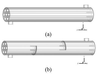
The field of study, shown schematically in Figure 1, is a three-dimensional channel circular horizontal shape of diameter Ds and length L, equipped with seven tubes in the first case, and with two segmental overlapping baffles in the second case, inside which water flows with mass flow of 1Kg/s, the regime is stationary and turbulent.
Figure 1. Geometry of the system under investigation (a) without baffles, (b) with baffles
The geometric dimensions are mentioned in Table 1 and Table 2. They are based on the study by Ozden and Tari [27].
Table 1. Geometric parameters of the heat exchanger [27]
|
Shell diameter |
Ds = 90 mm, |
|
Tube diameter |
d = 20 mm |
|
Tube bundle geometry and pitch |
Triangular, P = 30 mm |
|
Number of tubes |
Nt = 7 |
|
Tube length |
L = 600 mm |
|
Shell sideinlettemperature |
Te = 300 K |
|
Baflecut |
36% |
|
Number of baffles |
Nb = 2 |
|
Central baffles spacing |
B=86 mm |
Table 2. Physical properties of the materials [28]
|
|
ρ [kg/m3] |
Cp[J/kg°K] |
λ [w/m°K] |
|
Water |
989.2 |
4182 |
0.6 |
|
Aluminium |
2719 |
871 |
202 .4 |
2.2 Governing equations
In this numerical study, the following simplifying assumptions are adopted:
The flow governing equations are: continuity equations, the Navier-Stokes equation and the energy equation. These equations are used to simulate the steady incompressible fluid flow and the heat transfer within the computational domain may s' written in the following form:
Continuity:
$\frac{\partial\left(\rho. u_{i}\right)}{\partial x_{i}}=0$ (1)
Momentum:
$\frac{\partial u_{i} u_{j}}{\partial x_{i}}=-\frac{1}{\rho} \frac{\partial P}{\partial x_{i}}+\frac{\partial}{\partial x_{j}}\left(\left(v+v_{t}\right)\left(\frac{\partial u_{i}}{\partial x_{j}}+\frac{\partial u_{j}}{\partial x_{i}}\right)\right)$ (2)
Energy:
$\frac{\partial\left(u_{i} T\right)}{\partial x_{i}}=\rho \frac{\partial}{\partial x_{i}}\left(\left(\frac{v}{\operatorname{Pr}}+\frac{v_{t}}{\operatorname{Pr}_{t}}\right) \frac{\partial T}{\partial x_{i}}\right)$ (3)
Turbulence kinetic energy k:
$u_{i} \frac{\partial k}{\partial x_{i}}=\frac{\partial}{\partial x_{i}}\left[\left(v+\frac{v_{t}}{\sigma_{k}}\right) \frac{\partial k}{\partial x_{i}}\right]+\Gamma-\varepsilon$ (4)
Energy dissipation ε:
$u_{i} \frac{\partial \varepsilon}{\partial x_{i}}=\frac{\partial}{\partial x_{i}}\left|\left(v+\frac{v_{t}}{\sigma_{\varepsilon}}\right) \frac{\partial \varepsilon}{\partial x_{i}}\right|+C_{1} \Gamma \varepsilon-C_{2} \frac{\varepsilon^{2}}{k+\sqrt{v \varepsilon}}$ (5)
Turbulent viscosity:
$v_{t}=C_{\mu} \frac{k^{2}}{\varepsilon}$ (6)
The turbulence production
$\Gamma=-\overline{u_{i}^{\prime} u_{j}^{\prime}} \frac{\partial u_{i}}{\partial x_{i}}=v_{t}\left(\frac{\partial u_{i}}{\partial x_{j}}+\frac{\partial u_{j}}{\partial x_{i}}\right) \frac{\partial u_{i}}{\partial x_{i}}$ (7)
The empirical constants for the realizable k-ε turbulence model are
$C_{1}=\max \left[0.43, \frac{\mu}{\left(\mu_{t}+5\right)}\right], C_{2}=1.9, C_{\mu}=0.09, \sigma_{k}=1.0$
$\sigma_{\varepsilon}=1.2,$ et $\operatorname{Pr}_{t}=0.09$.
The Reynolds number, the friction factor, the Nusselt number and the heat transfer are given by the following relations:
$\operatorname{Re}=\frac{\dot{m}}{A_{s}}\left(\frac{D_{e}}{\mu_{s}}\right)$ (8)
$f_{s}=e^{(0,576-0,19 \ln \mathrm{Re})}$ (9)
$N u(x)=\frac{h(x) D_{h}}{\lambda_{f}}$ (10)
The heat transfer rate:
$Q=\dot{m} C_{p, \text {eau}}\left(T_{\text {out}}-T_{\text {in}}\right)$ (11)
The heat transfer coefficient
$h=\frac{0,36 \lambda_{s}}{D_{e}} \operatorname{Re}_{s}^{0,55} \operatorname{Pr}_{s}^{1 / 3}$ (12)
The pressure drop is calculated by:
$\Delta p=\frac{f G_{s}^{2}\left(N_{b}+1\right) D}{2 \rho_{s} D_{e} \varphi_{s}}$ (13)
Then, Gs the shell-side mass flow rate, Nb is the number of baffles, D is the shell diameter, De is the shell equivalent diameter.
The shell-side pump power is calculated by:
$P_{s}=\frac{G_{s} \Delta p_{s}}{\rho_{s}}$ (14)
where, Ps is the pressure drop in the shell.
The improvement factor h thermal performance is defined as follows:
$\eta=\left.\frac{h}{h_{0}}\right|_{p p}=\left.\frac{N u}{N u_{0}}\right|_{p p}=\left(\frac{N u}{N u_{0}}\right)\left(\frac{f}{f_{0}}\right)^{-1 / 3}$ (14)
2.3 Boundary conditions
The dynamic and thermal behavior of the water in shell of heat exchanger provided with segmental baffles was analyzed for three values of mass flow rate of water, namely. For this, a uniform velocity was applied as a boundary condition to the hydraulic input of the computational domain. In addition, as a condition for the thermal limit, a constant temperature of Tw=177°C (450 K) was applied on the walls of the tubes. The temperature of the fluid used was set at Tin=27°C (300 K) to the inlet side. The conditions for hydraulic and thermal limits are chosen in accordance with that section of Ozden and Tari [27].
3.1 Numerical model
The governing equations of our problem with imposed boundary conditions are solved by the finite volume method [29], using the Fluent commercial code. The second-order upwind scheme is adopted to discretize the convective terms. The SIMPLE algorithm [29] is used for velocity-pressure coupling. Default under-relaxation factors of the solver are used to control the update of the calculated variables for each iteration.
3.2 Grid sensitivity
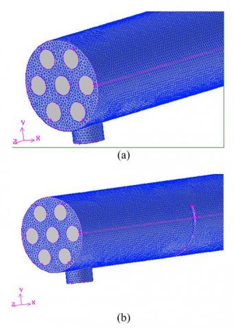
Figure 2. Meshed geometry: (a) without baffles, (b) with baffles
The three-dimensional geometry was created, and the computational domain is meshed with unstructured hexahedral grid in the shell as shown in Figure 2.
The geometry studied includes a fluid domain and a solid domain. For discretization, an unstructured mesh is generated in hexahedral elements adopted in the shell. Several tests were carried out (Table 3) in order to ensure the independence of the results with respect to the mesh adopted namely 491588 cells, 602587 cells and 805874 cells for the profile of the speed and the temperature in the section y = 0.045m.
Table 3. Validation of the mesh at the outlet of the shell
|
Grid |
Umax |
Vmax |
Wmax |
Tmax |
|
491588 |
0,00009 |
2,0404 |
0,0027 |
325,4014 |
|
602587 |
0,0001 |
2,0573 |
0,003 |
325,5871 |
|
805874 |
0,00011 |
2,0552 |
0,0029 |
325,2587 |
The results presented above show that the variation is very small and does not exceed 1%. The analysis of the results presented show that the choice of (805874) elements, give a good prediction for the present numerical model.
3.3 Model validation
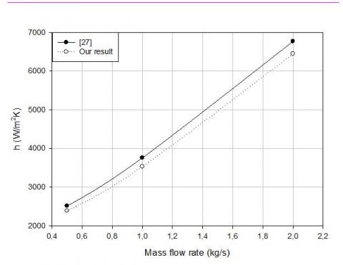
Figure 3. Average heat transfer coefficient
The model with six baffles in Figure 3 is validated with the data are proposed by Ozden and Tari [27], it is found that the overall transfer coefficient of the fluid corresponds to the results of the literature and the difference between the two cases is about 4%.
The results obtained from the elaborate calculation code, presented in the form of contours and curves, illustrate the advantage by using baffles in the shell and tube heat exchangers in order to improve their performance.
4.1 Dynamic behavior
4.1.1 Velocity contours
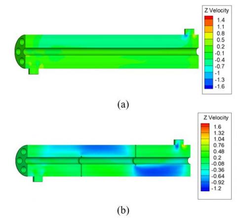
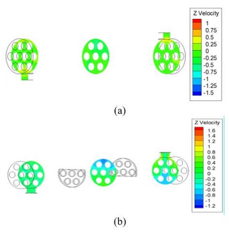
Figures 4 and 5 show the velocity contours in the shell and tube heat exchanger with and without baffles respectively. The velocity contour is represented by colors ranging from green (low velocity) to red (high velocity). From the numerical results it is noted that the values of the velocity are very low in the neighborhood of the walls, because of the presence of the strong gradients of friction. In the annular passage in the case without baffles, the velocity in the upper part of the shell is high and in the lower part is not used properly. In the annular passage in the case with baffles, the fluid velocity is markedly high, the difference in velocity is due to the difference between the two passage sections on the one hand and the presence of the recirculation zones of the water required by the baffle which results in a sudden increase in the dynamic pressure of the water.
Figure 4. Velocity contours x = 0, (a) without baffles, (b) with baffles
Figure 5. Velocity contours z = 0.58m; z = 0.3m; z = 0.02m, (a) without baffles, (b) with baffles
4.1.2 Velocity profiles in the shell
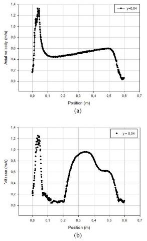
A presentation of the velocity distribution along the two exchangers in the section y = 0.04m has illustrated in this figure. Figure 6 (a) shows a decrease in the velocity along the shell, the fluid does not encounter any obstacle, its velocity decreases with the sudden enlargement and the lack of baffles.
Figure 6 (b) shows an increase in velocity from the first baffle due to abrupt narrowing of the passage section, is a decrease in velocity from z = 0.02m because the fluid located in the zone of recirculation after the baffle. The velocity of the flow in the shell of the case without baffle reaches maximum values of the order of 12% of the initial velocity, and in the case with baffles reaches 19% of the initial velocity.
Figure 6. Velocity distribution at y = 0.04m; (a) without baffles, (b) with baffles
4.1.3 Pressure drop in the shell
Figure 7. Pressure drop contours at x = 0, (a) without baffles, (b) with baffles
Figure 7 show the pressure drop in the two shell and tube heat exchangers with baffles and without baffles respectively.
This high pressure drop after the two baffles is caused by, the jet of fluid by high velocity at the baffles breaches, and then the fluid separate of the baffles causes a sudden change in the flow direction and screamed zones of recirculation.
4.2 Thermal behavior
4.2.1 Temperature contours
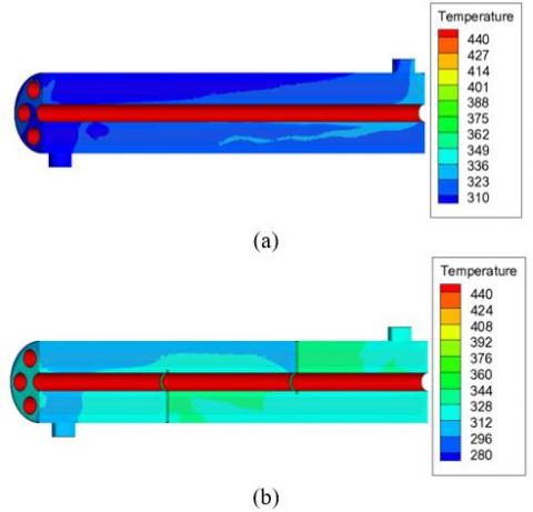
Figure 8. Temperature contours at x = 0, (a) without baffles, (b) with baffles
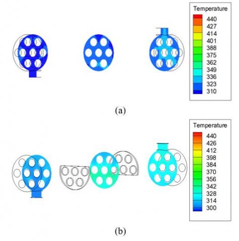
Figure 9. Temperature contours z = 0.58m; z = 0.3m; z = 0.02m, (a) without baffles, (b) with baffles
Figures 8 and 9 show the isothermal in the two shell and tube heat exchangers with baffles and without baffles respectively. The temperature contour is represented by colors ranging from green (low temperature) to red (high temperature). At the entrance of the two exchangers there is a green outline indicates the temperature of the fluid inlet, begins to vary from the center of the lower middle of the shell of the case without baffles, varies from the first baffle to the case with baffles. The temperature contours presented for the two cases show an increase in temperature and important values of the region near the tubes and at the level of second baffle. In the case with baffles the field of the temperature shows a low temperature in the first flow passage and an average temperature in the second passage to the baffles.
4.2.2 Temperature profiles in the shell
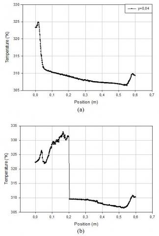
Figure 10. Temperature distribution at y = 0.04m, (a) without baffles, (b) with baffles
In Figure 10 (a) it is found that the fluid temperature increases slightly in the shell, the lack of baffles, is an additional factor of attenuation of the turbulence in the shell.
In Figure 10 (b) it is found that in the regions after the baffle the temperature is increased sharply. The fluid temperature increases as soon as the fluid is again in contact with the baffle, because the change in the direction of flow produced by the baffle, the highest value of the temperature appears behind the baffle.
4.3 Study of velocity and temperature profiles around 2nd baffle
The understanding of the baffle effect studied can be quantified by plotting the velocity and temperature profiles namely upstream (z = 0.15m) downstream (z = 0.25m) of the baffle for the two configurations.
There is a slight deformation of the velocity field in the two sections in the case without baffles; the decreased of velocity following the axis of the flow is its maximum value of this configuration is 0.52m/s. The impact of the baffles on the structure of the turbulent flow is shown in Figure 11, we clearly see a strong deformation of the velocity field close to the baffle, the velocity profile is tightening more and more in the upper part of the shell before the baffle and in the lower part of the shell after the baffle, while in its free segment, the flow begins to accelerate, the maximum value to observe after the baffle and 1,15m/s.
Figure 11. Velocity profile, (a) without baffles, (b) with baffles
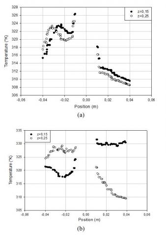
Figure 12. Temperature profile, (a) without baffles, (b) with baffles
The flow structure in the case with baffles is characterized by large deformations and large recirculation regions; it will significantly influence the distribution of the temperature field and will allow a better mixing of the fluid that will stimulate the heat transfer. If we take the same for y = 0.04m for the two studied cases we have, for the simple case the fluid temperature is 308.5°K and 309.75°K; it is a point having 309°K and 330°K in the case with baffles so clearly clear the role of obstacle in these devices.
4.4 Overall performance factor
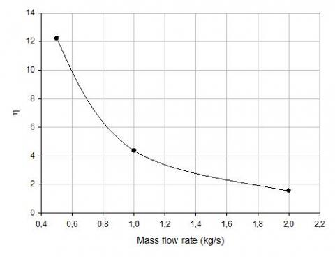
Figure 13 shows the performance factor for different mass flow rates. When the mass flow increases the performance decreases because the maximum observed value of the performance index for mass flow 0.5 kg is 12.25 means that the heat transfer coefficient is 12.25 times the greater that the pressure drop, at 2 kg the ratio between these two decisive parameters is 1.58, so the heat transfer coefficient is greater than 1.58 times for the pressure drop. The performance evaluation factor decreased because the contact time to the tubes is decreased.
Figure 13. Overall performance factor
4.5 Performance of the heat exchanger
Table 4 shows the evolution of the temperature, the heat transfer coefficient, the pressure drop, the total heat transfer rate, the pumping costs calculated in the two heat exchangers studied. The heat transfer coefficient, the pressure drop, the total heat transfer rate, the pumping costs increase by 1.86% and 21.67% and 1.11%, and 21.68% successively. The baffle favors vortices over the simple flow case, and increasing the Reynolds number greatly increases the rate of heat transfer by introducing large recirculation zones.
Table 4. Performance of the heat exchanger without baffles and with baffles
|
Parameter |
Without baffles |
With baffles |
|
T (°K) |
322,51 |
325,15 |
|
h (W/m2°K) |
954,66 |
1779,55 |
|
ΔP (pa) |
18,79 |
407,266 |
|
Q (W) |
94182 |
105278 |
|
P (kW) |
0,019 |
0,412 |
A numerical study based on the finite volume method using the SIMPLE algorithm is undertaken in this paper. It consists of stationary turbulent flow in forced convection mode, an incompressible fluid circulating inside a heat exchanger without and with baffles.
The profiles and the velocity fields as well as the profiles and the temperature distributions in the shell were obtained for all the geometry upstream, downstream of the baffles, the velocity profiles are more and more affected by the latter and the fluid is accelerating more and more as it moves towards the outlet of the shell.
The simple case assures us a high velocity along the shell, its measurement more than twelve times the reference velocity , the case with baffles ensures a velocity in the shell nineteen times higher than the reference velocity, the disturbance the higher and obtained upstream of the second baffle, the swirl zones are responsible for the increase in fluid temperature.
The pressure drop is a great importance in the design of the shell and tube heat exchangers because the pumping costs are strongly related to the pressure drop, and thus the decrease of the parameter results in lower operating costs.
The baffles direct the fluid and cause the appearance of a combined flow of two longitudinal and transverse spills, is the flow perpendicular to the tubes promotes heat transfer.
In the case of the presence of baffles, the flow along the shell is very complex because of the back-mixing, as a result these baffles significantly influence the pressure drop due to rapid changes in direction, expansion and contraction.
The exchanger performance in the case of presence of the baffles increases to 1.86% for the heat transfer coefficient, to 21.67% for the pressure drop, 2.46% for the Nusselt number, therefore, the baffles are expected to improve heat transfer and circulate the fluid in the shell according to an expected flow pattern.
|
Ds |
Shell size (mm) |
|
d |
Tube diameter (mm)specific |
|
Nt L |
Number of tubes Heat exchanger length (mm) |
|
Nu T |
local Nusselt number along the heat source Shell side inlet temperature (°K) |
|
w Bc Nb h u, v, w x, y, z C1ε ; C2ε ; Cμ m f Cp k P Re Greek symbols |
wall Baffle cut (%) Number of baffles Heat transfer coefficient (W/(m2K) velocity components (m/s) positions coordinates Constants of transport equations Mass flow rate (kg/s) Friction coefficient. Specific heat at constant pressure, J/Kg.K Turbulent kinetic energy Pressure, Pa Reynolds number
|
|
ε |
dissipation rate of turbulence energy |
|
ρ |
Density, kg/m |
|
f μl, μtμe |
Molecular, turbulent and effective viscosity, Pa.s |
|
ν |
Kinematics viscosity, pl |
|
µ |
dynamic viscosity, kg. m-1.s-1 |
[1] Pan, M., Jamaliniy, S., Smith, R., Bulatov, I., Gough, M., Higley, T., Droegemueller, P. (2013). New insights to implement heat transfer intensification for shell and tube heat exchangers. Energy, 57: 208-221. https://doi.org/10.1016/j.energy.2013.01.017
[2] Master, B.I., Chunangad, K.S. Pushpanathan, V. (2003). Fouling mitigation using helixchanger heat exchangers. Proceedings of the ECI Conference on Heat Exchanger Fouling and Cleaning: Fundamentals and Applications. https://dc.engconfintl.org/heatexchanger/43
[3] Saffarian, M.R., Fazelpour, F., Sham, M. (2019). Numerical study of shell and tube heat exchanger with different cross-section tubes and combined tubes. International Journal of Energy and Environmental Engineering, 10 (1): 33-46. https://doi.org/10.1007/s40095-019-0297-9
[4] Bhutta, M.M.A., Bashir, M.H., Khan, A.R., Ahmad, K.N., Khan, S. (2012). CFD applications in various heat exchangers design: A review. Applied Thermal Engineering, (32): 1-12. https://doi.org/10.1016/j.applthermaleng.2011.09.001
[5] Youcef-Ali, S. (2005). Study and optimization of the thermal performances of the offset rectangular plate fin absorber plates, with various glazing. Renewable Energy, 30(2): 271-280. https://doi.org/10.1016/j.renene.2004.04.009
[6] Youcef-Ali, S., Desmons, J.Y. (2006). Numerical and experimental study of a solar equipped with offset rectangular plate fin absorber plate. Renewable Energy, 31(13): 2063-2075. https://doi.org/10.1016/j.renene.2005.10.008
[7] Moummi, N., Youcef-Ali, S., Moummi, A., Desmons, J.Y. (2004). Energy analysis of a solar air collector with rows of fins. Renewable Energy, 29: 2053-2064. https://doi.org/10.1016/j.renene.2003.11.006
[8] Yang, Y.T., Hwang. C.Z (2003). Calculation of turbulent flow and heat transfer in a porous-baffled channel. International Journal of Heat and Mass Transfer, 46(5): 771-780. https://doi.org/10.1016/S0017-9310(02)00360-5
[9] Patankar, S.V., Sparrow, E.M. (1977). Fully developed flow and heat transfer in ducts having stream wise-periodic variations of cross-sectional area. Journal of Heat Transfer, 99: 180-186. https://doi.org/10.1115/1.3450666
[10] Kelkar, K.M., Patankar, S.V. (1987). Numerical prediction of flow and heat transfer in parallel plate channel with staggered fins. Journal of Heat Transfer, 109: 25-30. https://doi.org/10.1115/1.3248058
[11] Saim, R., Benzenine, H., Oztop, H.F., Al-Salem, K. (2013). Turbulent flow and heat transfer enhancement of forced convection over heated baffles in a channel effect of pitch of baffles. Journal of Numerical Methods for Heat & Fluid Flow, 23(4): 613-633. https://doi.org/10.1108/09615531311323773
[12] Lopez, J.R., Anand, N.K., Fletcher, L.S. (1996). Heat transfer in a three-dimensional channel with baffles. Numerical Heat Transfer, 30: 189-205. https://doi.org/10.1080/10407789608913835
[13] Yuan, Z.X., Tao, W.Q., Wang, Q.W. (1999). Numerical prediction for laminar forced convection heat transfer in parallel-plate channels with stream wise-periodic rod disturbances. International Journal for Numerical Methods in Fluids, 28: 1371-1387. https://doi.org/10.1002/(SICI)1097-0363(19981215)28:9<1371::AID-FLD774>3.0.CO;2-A
[14] Cheng, C.H., Huang, W.H. (1991). Numerical prediction for laminar forced convection in parallel-plate channels with transverse fin arrays. International Journal of Heat and Mass Transfer, 34(11): 2739-2749. https://doi.org/10.1016/0017-9310(91)90232-4
[15] Saim, R., Bouchenafa, R., Benzenine, H., Oztop, H.F., Al-Salem, K., Abboudi, S. (2013). A computational work on turbulent flow and heat transfer in a channel fitted with inclined baffles. Heat Mass Transfer, 49: 761-774. https://doi.org/10.1007/s00231-013-1121-3
[16] Guo, Z., Anand, N.K. (1997). Three-dimensional heat transfer in a channel with a baffle in the entrance region. Numerical Heat Transfer, Part A, 31(1): 21-30. https://doi.org/10.1080/10407789708914023
[17] Taher, F.N., Movassag, S.E., Razmi, K. (2012). Baffle space impact on the performance of helical baffle shell and tube heat exchangers. Applied Thermal Engineering, 44: 143-149. https://doi.org/10.1016/j.applthermaleng.2012.03.042
[18] Chang, B.H., Mills, A.F. (1993), Turbulent flow in a channel with transverse rib heat transfer augmentation. International Journal of Heat and Mass Transfer, 36: 1459-1469. https://doi.org/10.1016/S0017-9310(05)80056-0
[19] Yang, Y.T., Hwang, C.Z. (2003). Calculation of turbulent flow and heat transfer in a porous-based channel. International Journal of Heat and Mass Transfer, 46(5): 771-780. https://doi.org/10.1016/S0017-9310(02)00360-5
[20] Bazdidi-Tehrani, F., Naderi-Abadi, M. (2004). Numerical analysis of laminar heat transfer in entrance region of a horizontal channel with transverse fins. International Communications in Heat and Mass Transfer, 31(2): 211-220. https://doi.org/10.1016/S0735-1933(03)00226-4
[21] Li, H., Kottket, V. (1998). Effect of baffle spacing on pressure drop and local heat transfer in shell-and-tube heat exchangers for staggered tube arrangement. Journal of Heat Masse Transfer, 41(10): 1303-1311. https://doi.org/10.1016/S0017-9310(97)00201-9
[22] Dutta, P., Hossain, A. (2005) Internal cooling augmentation in rectangular channel using two inclined baffles. International Journal of Heat and Fluid Flow, 26: 223-232. https://doi.org/10.1016/j.ijheatfluidflow.2004.08.001
[23] Belmiloud, M.A., chemloul, N.S. (2015). Effect of baffle number on mixed convection within a ventilated cavity. Journal of Mechanical Science and Technology, 29: 4719-4727. https://doi.org/10.1007/s12206-015-1019-8
[24] Benzenine, H., Saim, R., Abboudi, S., Imine, O., Oztop, H.F., Abu-Hamdeh, N. (2018). Numerical study of a three-dimensional forced laminar flow in a channel equipped with a perforated baffle. Journal Numerical Heat Transfer, Part A: Applications, An International Journal of Computation and Methodology, 73(12): 881-894. https://doi.org/10.1080/10407782.2018.1486645
[25] Cucumo, M., Ferraro, V., Kaliakatsos, D., Mele, M., Galloro, A., Schimio, R., Le Pera, G. (2016). Thermohydraulic analysis of a shell-and-tube helical baffles heat exchanger. International Journal of Heat and Technology, 34(2): S255-S262. http://dx.doi.org/10.18280/ijht.34S210
[26] Dipankar De, Kanti Pal, T., Bandyopadhyay, B. (2017). Helical baffle design in shell and tube type heat exchanger with CFD analysis. International Journal of Heat and Technology, 35(2): 378-383. https://doi.org/10.18280/ijht.350221
[27] Ozden, E., Tari, I. (2010). Shell side CFD analysis of a small shell-and-tube heat exchanger. Energy Conversion and Management, 51: 1004-1014. https://doi.org/10.1016/j.enconman.2009.12.003
[28] ANSYS Fluent Inc. (2006). Fluent 6.3 User’s Manual. Fluent Inc. Centrera Resource Park, 10 Cavendish Court, Lebanon, USA.
[29] Patankar, S.V. (1980). Numerical heat transfer and fluid flow. Engineering & Technology, 214 pages. https://doi.org/10.1201/9781482234213