Linjing Xu* | Guoyong Wang | Tianyu Liu | Naizhen Liu | Shicheng Zhang | Shiyao Sun
© 2019 IIETA. This article is published by IIETA and is licensed under the CC BY 4.0 license (http://creativecommons.org/licenses/by/4.0/).
OPEN ACCESS
Although most carbonate reservoirs are naturally fractured, no quantitative research has been conducted on the calculation of acid leakoff in naturally fractured carbonate reservoirs. In this paper, a comprehensive dual-porosity gas/acid flow model is developed to predict the acid leakoff in naturally fractured carbonate gas reservoirs. The model considers many factors, including the acid-rock reaction, the acid flow, and the fracture width variation caused by rock dissolution on the fractured surfaces. On this basis, a numerical simulator was designed for the model, verified through comparison with Eclipse, and applied to simulate an actual naturally fractured gas carbonate reservoir. The results show that the acid leakoff is completely different from that without considering acid-rock reaction on the fracture surfaces. The acid leakoff is controlled by viscosity and compressibility, and the leakoff rate increased first and then decreased. Meanwhile, the leakoff rate of the traditional non-reactive liquid decreased continuously. Moreover, the acid concentration increased the main natural fracture width and the acid leakoff, revealing the importance to maintain a high acid viscosity for acid fracturing. The main natural fractures (width>10μm) dominated the leakoff, and overshadowed the contribution of micro-fractures (width<5μm) to leakoff. Finally, the main natural fractures exerted a greater impact on acid leakoff than any other part of the reservoir. The research findings provide insights into the mechanism of acid leakoff in naturally factured formation and offer an accurate method for calculating leakoff in naturally fractured carbonate gas reservoirs.
acid fracturing, acid leakoff, main natural fracture, naturally fractured carbonate gas reservoir, acid-rock reaction
Most carbonate reservoirs have natural fractures. To connect these fractures, the carbonate reservoirs are generally stimulated by matrix acidizing or acid fracturing. Matrix acidizing mainly improves the well productivity by eliminating the low-permeable barrier near the wellbore. The most frequently used acid in matrix acidizing is 5~28% HCl [1]. Compared with matrix acidizing, acid fracturing enjoys a broad spectrum of effects and a wide range of application. However, this stimulation method often faces severe acid leakoff, as the acid may flow along the natural fractures and react with the fracture surfaces. The leakoff smoothens the etched surface of the artificial hydraulic fracture, constrains the fracture propagation, limits the penetration distance of acid, resulting in poor or ineffective production of the wells. Thus, acid leakoff poses a major threat to the success of reservoir stimulation. Nevertheless, there is no report on the quantitative simulation of naturally fractured carbonate reservoirs, or the theoretical analysis on the acid fracturing of such reservoirs.
Since the basic leakoff equation was proposed by Carter [2] in 1957, many scholars have conducted experiments and theoretical analyses on the leakoff of fracturing fluid [3-5], and came to the consensus that the leakoff is controlled by the filter cake, viscous flow and compressibility. This leakoff mechanism has been adopted widely in fracturing simulation and design. On this basis, various methods and models have been developed to compute or simulate the leakoff in different types of reservoirs. In 2000, James [6] qualitatively analyzed the effects of natural fracturs on hydraulic fracturing in naturally fractured carbonate reservoirs. Li et al., Guo and Liu [7, 8] established a mathematical model to compute the leakoff in fractured vuggy reservoirs, put forward a numerical solution to the model, and applied the model in sample calculation. Economides, Hill et al., [9, 10] proposed a leakoff calculation method for fracturing fluid based on the net pressure of fractures, and explored the effect of fracturing fluid leakoff on fracture propagation. Despite the various studies on fracturing fluid leakoff, few models have been created to analyze the influencing factors of the leakoff.
The traditional fracturing fluid (non-reactive liquid) leakoff models assume that the acid forms a filter cake on the fracture surface and the leakoff is controlled by the filter cake, viscous flow and compressibility. These simple assumptions cannot reflect the actual situation of acid fracturing [2]. In fact, the acid will continuously penetrate the filter cake and directly interact with the acidic rock. The acid-rock reactions make it hard to form filter cake on fracture surfaces [11-13], further expand the fractures, and lead to greater leakoff. Some leakoff models have been built for matrix acidizing, but few for acid fracturing in naturally fractured reservoirs. Neither have the influencing factors of the leakoff been discussed in such reservoirs.
In a relatively homogenous and nonfractured carbonate reservoir, the fracturing acid selectively passes through large pores. The rapid acid-rock reaction expands these pores into wormholes [14, 15]. Some scholars [16-18] have experimentally explored the effect of wormholes on acid leakoff. Hill et al., [19] designed an acid leakoff analysis model focusing on the effect of wormholes on leakoff in nonfractured reservoirs, revealing that the wormholes push up the leakoff to 120 % from the level of non-reactive fluid simulation in high compressible reservoirs (e.g. gas reservoirs) and have no major impact in low compressible reservoirs (e.g. oil reservoirs). However, the existing wormhole models mainly targets matrix acidizing.
In a naturally fractured carbonate reservoir, the flow and reactions of the fracturing fluid differ from those in a relatively homogenous and nonfractured reservoir. As said above, there is no acid leakoff model for such a reservoir. Some relevant studies are introduced briefly here. Siemers and Dreybrodt [20] studied the early development of karst aquifers using the percolation network of fractures in limestone, and simulated the flow and dissolution in limestone formation with stochastic primary percolation network. Their simulation shows that the water flows evenly through all fractures in the early phase, but through a single main channel to the entire network at the breakthrough moment. Dong [21] modelled the acid fracturing of naturally fractured reservoirs, pointing out that the acid can enter the formation by several meters through the main channel in the fracture network.
In view of the above, this paper sets up a novel numerical model to simulate the acid leakoff in acid fracturing of naturally fractured carbonate gas reservoirs. Specifically, the distribution of the wide natural fractures was simulated, which are located periodically around the hydraulic fracture, and the remaining micro-fractures were considered as the dual-porosity part. Then, a two-phase model was established for the acid flow and the gas reservoir in light of the gas flow features, the acid concentration through acid-rock reaction, and the width variation of natural fractures. The model was solved by coupling the dual-porosity part, the main natural fractures and the hydraulic fracture. Based on implicit pressure explicit saturation (IMPES), a numerical simulation was carried out to analyze the effects of all influencing factors on acid leakoff.
2.1 Physical model and hypotheses
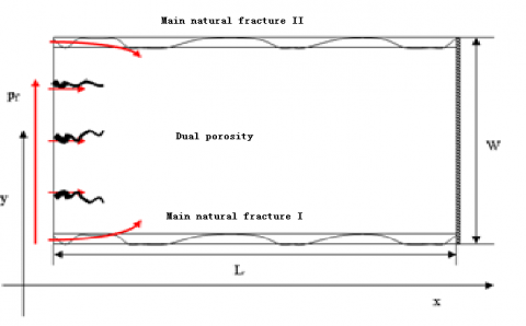
The acid leakoff in the acid fracturing of a naturally fractured carbonate gas reservoir is illustrated in Figure 1, where the center is a hydraulic fracture, the bold lines are the main natural fractures and the fine lines are micro-fractures. Here, the formation with micro-fractures is characterized by a dual-porosity model.
In acid fracturing, there is a large pressure difference between the inside and the outside of the hydraulic fracture. The pressure gradient points perpendicularly to the surface direction of the hydraulic fracture (the x-direction). Thus, the acid leakoff mainly occurs along the x-direction. In the naturally fractured formation, the acid selectively passes through the main natural fractures, and diffuses to the facture surface. Then, the acid will react with the rock on the surface, thus widening the fracture.
Considering their periodical distribution around the hydraulic fracture, one of the main natural fractures was selected for simulation analysis. This main natural fracture is called a calculation unit and described in Figure 2 below, where the upper and lower boundaries are respectively the main natural fractures I and II, the center is the dual-porosity part, the left side is the hydraulic fracture and the right side is the distal end of the gas reservoir. The two main natural fractures have periodic boundaries. In the calculation unit, the acid flows into the gas reservoir from the main natural fractures I and II, and also through the dual-porosity part. The leakoff process in the calculation unit involves the flow in the dual-porosity part, the flow in the main natural fractures and the fluid exchange between these two parts.
Figure 1. Sketch map of the acid leakoff in acid fracturing of a naturally fractured carbonate reservoir
Figure 2. Sketch map of the calculation unit
2.2 Mathematical formulation and finite-difference approximation
2.2.1 The flows in the dual-porosity system
The acid leakoff model was set up based on the following hypotheses: (1) It is a 2D model with two phases, namely, the gas phase and the acid phase; (2) In the dual-porosity part, the flow from the micro-fracture system to the matrix system is in a pseudo steady state, that is, the acid flow of the matrix system is negligible; (3) The acid flow and the rock are weakly compressible with a constant compression coefficient; (4) The influence of gravity and capillary force is ignored; (5) The gas flow in the reservoir is a non-Darcy flow.
The classic Warren-Root dual-porosity model (1963) [22] was introduced to simulate the acid leakoff. The model consists of two overlapping continua: the micro-fracture system and the matrix system. The interaction between the two continua is controlled through a transfer factor α.
The acid and gas inside the fracture system flow linearly into the matrix. The continuity equations for the acid and gas in the micro-fractures can be expressed as:
Gas phase:
\(\nabla \left( {{\rho }_{g}}\frac{{{k}_{f}}{{k}_{rg}}}{{{\mu }_{g}}}\nabla {{p}_{f}} \right)+\frac{\sigma {{\rho }_{g}}{{k}_{m}}{{k}_{rg}}}{{{\mu }_{g}}}({{P}_{m}}-{{P}_{f}})=\frac{\partial }{\partial t}{{(\phi {{\rho }_{g}}{{s}_{g}})}_{f}}\) (1)
Acid phase:
\(\nabla \left( {{\rho }_{a}}\frac{{{k}_{f}}{{k}_{ra}}}{{{\mu }_{a}}}\nabla {{P}_{f}} \right)+\frac{\sigma {{\rho }_{a}}{{k}_{m}}{{k}_{ra}}}{{{\mu }_{a}}}({{P}_{m}}-{{P}_{f}})=\frac{\partial }{\partial t}{{(\phi {{\rho }_{a}}{{s}_{a}})}_{f}}\) (2)
With the fractures as the sources, the acid and gas flows in the matrix system can be depicted as:
Gas phase:
\(\frac{\sigma {{\rho }_{g}}{{k}_{m}}{{k}_{rg}}}{{{\mu }_{g}}}({{P}_{f}}-{{P}_{m}})=\frac{\partial }{\partial t}{{(\phi {{\rho }_{g}}{{s}_{g}})}_{m}}\) (3)
Acid phase:
\(\frac{\sigma {{\rho }_{a}}{{k}_{m}}{{k}_{ra}}}{{{\mu }_{a}}}({{P}_{f}}-{{P}_{m}})=\frac{\partial }{\partial t}{{(\phi {{\rho }_{a}}{{s}_{a}})}_{m}}\) (4)
where, $ρ_g=\frac{MP}{zRT}$. Note that $M=28.97γ_g^2$, $R=10.732$ $\frac{psia·ft^3}{lb_{mol}·R}$ and z is defined by Dranchuk and Abu-Kassem [23]:
$z=[A_1+\frac{A_2}{T_{pr}}+\frac{A_3}{T_{pr}^{3}}+\frac{A_4}{T_{pr}^4}+\frac{A_5}{T_{pr}^5}]{\rho}_{r}$ $+[A_6+\frac{A_7}{T_{pr}}+\frac{A_8}{T_{pr}^{2}}] \rho_{r}^{2}$ $-A_9[\frac{A_7}{T_{pr}}+\frac{A_8}{T_{pr}^{2}}]\rho_{r}^{5}$ $+{A_10}(1+{A_{11}}\rho_{r}^{2})\frac{\rho_{r}^{2}}{T_{pr}^{3}}exp(-{A_{11}}\rho_{r}^{2})+1.0$ (5)
where, A1=0.3265; A2=-1.07; A3=-0.5339; A4=0.01569; A5=-0.05165; A6=0.5475; A7=-0.7361; A8=0.1844; A9=0.1056; A10=0.6134; A11=07210; $ρ_r=0.27\frac{p_{pr}}{zT_{pr}}$; $p_{pr}=\frac{p}{p_{pc}(p_{pc}=677+15.0γ_g-37.5γ_g^2)}$; $T_{pr}=\frac{T}{T_pc}(T_{pc}=168+325γ_g-12.5γ_g^2)$.
Considering its implicitness, the z value can be iteratively determined by the following correlation function:
$f\left( z \right)\equiv {{B}_{1}}{{z}^{-1}}+{{B}_{2}}{{z}^{-2}}-{{B}_{3}}{{z}^{-5}}+{{B}_{4}}\left( {{z}^{-2}}+{{B}_{5}}{{z}^{-4}} \right)\exp \left( -{{B}_{5}}{{z}^{-2}} \right)+1.0-z$
where,
$B_1=[A_1+\frac{A_2}{T_{pr}} +\frac{A_3}{T_{pr}^3} +\frac{A_4}{T_{pr}^4}+\frac{A_5}{T_{pr}^5}](0.27\frac{p_{pr}}{T_{pr}})$;
$B_2=[A_6+\frac{A_7}{T_{pr}} +\frac{A_8}{T_{pr}^2}](0.27\frac{p_{pr}}{T_{pr}}^2)$;
$B_3=A_9[\frac{A_7}{T_{pr}}+\frac{A_8}{T_{pr}^2}](0.27\frac{p_{pr}}{T_{pr}}^5)$;
$B_4=A_10\frac{0.27\frac{p_{pr}}{T_{pr}}^2}{T_pr^3}$;
$B_5=A_11(0.27\frac{p_{pr}}{T_{pr}^2}$;
Since P and T are given, it is possible to find the z that satisfies :
$f'(z)=-1-B_1z^{-2}-2B_2z^{-3}+5B_3z^{-6}+2B_4(B_5^2 z^{-7}-B_5 z^{-5}-z^{-3})⋅exp(-B_5 z^{-2})$
The following equations can be constructed to describe the flows in the dual-porosity part [24]:
$μ_g=10^{-4}K exp[X(ρ_g/62.4)^Y]$
$Mw=28.97γ_g$
$K=\frac{(9.4+0.02Mw)T^1.5}{209+19Mw+T}$
$X=3.5+(986/T)+0.01Mw$
$Y=2.4-0.2X$
where, the subscript f and m represent the fracture system and the matrix system, respectively; P is the acid pressure in the fracture system; Po is the initial pressure of the reservoir; is a shape-dependent constant; is the porosity of the reservoir; ρg and ρa are gas and acid densities, respectively; kf is the permeability of fracture system; krg and kra are the relative permeabilities of gas and acid, respectively; μg and μa are the viscosities of gas and acid, respectively; Sg and Sa are the saturations of gas and acid, respectively; rg is the dimensionless relative density of gas. All parameters are in SI units.
The dual-porosity part was simulated with the following boundary conditions: the initial pressures of the matrix system Pm and the fracture system Pf are the same everywhere. For the micro-fracture block, the inner boundary condition is that the pressure is the same as the hydraulic fracture pressure, and the outer boundary condition is that the pressure is that of a no-flow boundary at a known distance (closed boundary). These conditions can be expressed as:
Initial conditions: $P_m(x,y,t)|_{t=0}=P_0$, $P_f(x,y,t)|_{t=0}=P_0$; $S_{fg}(x,y,t)|_{t=0}=S_{oi}$, $S_{fa}(x,y,t)|_{t=0}=S_{wi}$, $S_{mg}(x,y,t)|_{t=0}=S_{oi}$, $S_{ma}(x,y,t)|_{t=0}=S_{wi}$
Inner boundary condition: $P_f(0,y)=P_F$
Outer boundary condition: $\frac{∂p_f}{∂x}|L,y=0$
where PF is the pressure in the hydraulic fracture.
2.2.2 Flows in main natural fractures
The main natural fractures were modelled under the following assumptions: (1) The fractures are vertical and cubic in shape; (2) the fractures are homogenous with isotropic permeability; (3) the flows in the fractures are Darcy flows; (4) the fracture width varies with time, due to the rock dissolution on the fracture surface.
This paper traces the acid flow and acid-rock reaction in the main natural fractures I and II. The continuity of the acid phase can be expressed as:
$\frac{\partial }{\partial x}\left( {{W}_{l}}{{\rho }_{a}}\frac{k{{k}_{ra}}}{\mu }\frac{\partial {{P}_{l}}}{\partial x} \right)-2{{q}_{l}}=\frac{\partial }{\partial t}\left( {{\rho }_{a}}{{W}_{l}} \right)$ (5)
The width of the main natural factures is expanded when the acid etches the fracture surface before entering into the formation. Thus, the variation of a main natural fracture width can be described as the percentage of the acid in the fracture that leaks to the dual-porosity part [20]:
\(\frac{\partial {{W}_{l}}}{\partial t}=\frac{\beta {{\rho }_{a}}{{C}_{i}}{{C}_{D,l}}}{{{\rho }_{r}}\left( 1-\phi \right)}\left( 2\eta {{q}_{l}}+2{{k}_{g}} \right)\) (6)
where, l is I or II; $W_l$ and $P_l$ are the width and pressure of the main natural fracture; $q_l$ is the flow volume from the main natural fracture to the dual-porosity part ($q_l=\frac{ρ_akk_ra}{μ}\frac{∂P_l}{∂y}$); β is the dissolving power of the acid under gravitation (kg rock/kg acid); ρ is the rock density (m); CD is the ratio of the compression coefficient of the acid Ca to the acid concentration Ci; kg is the mass transfer coefficient (m). In addition, the second term in equation (6) describes the flow from the main natural fractures to the micro-fracture system.
The main natural fractures were simulated with the following boundary conditions: the initial pressures of the main natural fractures are the same everywhere; the flow pressure at the inner boundary is the same as the hydraulic fracture pressure; the outer boundary is a closed boundary. These conditions can be expressed as:
Initial conditions: $P_F(x,t)|_(t=0)=P_0$, $S_{Fo}(x,t)|_(t=0)=S_{oi}$, $S_{Fw}(x,t)|_{t=0}=S_{wi}$
Inner boundary condition: $P_l|x=0=P_F$
Outer boundary condition: $\frac{∂P_l}{∂x}|x=L=0$
2.2.3 Distribution of acid concentration in main natural fractures
The acid concentration changes through the acid-rock reaction. The mass balance of the acid in the main natural fractures can be expressed as:
\([\frac{\partial }{\partial x}\left( {{C}_{D,l}}{{u}_{l}}{{w}_{l}} \right)-2{{C}_{D,l}}{{q}_{l}}-2{{C}_{D,l}}{{k}_{g}}=\frac{\partial }{\partial t}\left( {{W}_{l}}{{C}_{D,l}} \right)\) (7)
where, l, CD and kg are the same as those in equation (6).
The acid concentration in main natural fractures was simulated with the following boundary conditions: the initial acid concentrations (CIand CII) in main natural fractures I and II are non-acid flows; both CIand CII are 1 on the inner boundary, and equal to the flow in the outer reservoir on the outer boundary. These conditions can be expressed as:
Initial conditions: $C_I(x,t)|_{t=0}=0$, $C_{II}(x,t)|_{t=0}=0$,
Inner boundary condition: $C_{D,I}|x=0=1$, $C_{D,II}|x=0=1$
Outer boundary condition: $\frac{∂C_{D,I}}{∂x}|x=L=0$, $\frac{∂C_{D,II}}{∂x}|x=L=0$
2.2.4 Finite-difference approximation
The IMPES method was adopted to determine the pressure and saturation distributions. The former was obtained through implicit solution of the acid and gas phase equations, while the latter was acquired through explicit solution to the equation. Since viscosity and the z-factor are functions of pressure, the pressure field, viscosity and z-factor were solved one after another, and the difference equations were solved iteratively by successive over-relaxation (SOR).
(1) Implicit solution of pressure in matrix system
Combining equations (1) and (2), we have
\({{B}_{g}}\left\{ \nabla \left( \mathop{\lambda }_{g}\nabla {{P}_{f}} \right)+\alpha \mathop{\lambda }_{g}\left( {{P}_{m}}-{{P}_{f}} \right) \right\}\)+\({{B}_{a}}\left\{ \nabla \left( \mathop{\lambda }_{a}\nabla {{P}_{f}} \right)+\alpha \mathop{\lambda }_{a}\left( {{P}_{m}}-{{P}_{f}} \right) \right\}\)=\(\phi \mathop{C}_{1}\frac{\partial {{P}_{f}}}{\partial t}\) (8)
where \({{\lambda }_{l}}=\frac{k{{k}_{rl}}}{{{\mu }_{l}}{{B}_{l}}}\) (l=o or a); ${{C}_{1}}={{c}_{R}}+{{s}_{g}}{{c}_{g}}+{{s}_{a}}{{c}_{a}}$; \({{c}_{g}}=-\frac{1}{{{\rho }_{g}}}\frac{\partial {{\rho }_{g}}}{\partial p}\); \({{c}_{a}}=-\frac{1}{{{\rho }_{a}}}\frac{\partial {{\rho }_{a}}}{\partial p}\).
Eq. (8) can be rewritten in the finite-difference form:
\({{c}_{i,j}}{{P}_{i,j-1}}+{{a}_{i,j}}{{P}_{i-1,j}}+{{e}_{i,j}}{{P}_{i,j}}+{{b}_{i,j}}{{P}_{i+1,j}}+{{d}_{i,j}}{{P}_{i,j+1}}={{D}_{i,j}}\) (9)
where,
\({{b}_{i,j}}=\frac{1}{\Delta {{x}_{i}}\Delta {{x}_{i+\frac{1}{2}}}}\left( {{\lambda }_{g,i+\frac{1}{2},j}}{{B}_{g,i,j}}+{{\lambda }_{a,i+\frac{1}{2},j}}{{B}_{a,i,j}} \right)\);
\({{a}_{i,j}}=\frac{1}{\Delta {{x}_{i}}\Delta {{x}_{i-\frac{1}{2}}}}\left( {{\lambda }_{g,i-\frac{1}{2},j}}{{B}_{g,i,j}}+{{\lambda }_{a,i-\frac{1}{2},j}}{{B}_{a,i,j}} \right)\);
\({{d}_{i,j}}=\frac{1}{\Delta {{y}_{j}}\Delta {{y}_{j+\frac{1}{2}}}}\left( {{\lambda }_{g,i,j+\frac{1}{2}}}{{B}_{g,i,j}}+{{\lambda }_{a,i,j+\frac{1}{2}}}{{B}_{a,i,j}} \right)\);
\({{c}_{i,j}}=\frac{1}{\Delta {{y}_{j}}\Delta {{y}_{j-\frac{1}{2}}}}\left( {{\lambda }_{g,i,j-\frac{1}{2}}}{{B}_{g,i,j}}+{{\lambda }_{a,i,j-\frac{1}{2}}}{{B}_{a,i,j}} \right)\);
\({{e}_{i,j}}=-\left( {{a}_{i,j}}+{{b}_{i,j}}+{{c}_{i,j}}+{{d}_{i,j}}+\frac{{{\left( \phi {{C}_{1}} \right)}_{i,j}}}{\Delta t}+\alpha {{\left( {{B}_{g}}\mathop{\lambda }_{g}+{{B}_{a}}\mathop{\lambda }_{a} \right)}_{i,j}} \right)\);
\({{D}_{i,j}}=-\alpha \left( {{B}_{g}}\mathop{\lambda }_{g}+{{B}_{a}}\mathop{\lambda }_{a} \right){{\left( {{P}_{m}} \right)}_{i,j}}-\frac{{{\left( \phi {{C}_{1}} \right)}_{i,j}}}{\Delta t}\left( {{P}_{f}} \right)_{i,j}^{n}\).
(2) Explicit solution of saturation in matrix system
The acid phase differential equation can be obtained from equation (2):
$Δ(λ_a^n ΔP_f^{n+1})+αλ_a^n(P_m-P_f )^n=\frac{1}{Δt}[(\frac{ϕs_a C_2 P_f}{B_a})^{n+1}-\frac{ϕs_a C_2 P_f}{B_a}^n]+\frac{1}{Δt}[(\frac{ϕs_a}{B_a}^{n+1}-\frac{ϕs_a}{B_a}^n]$
where, $C_2=c_R+c_a$. After calculating the acid saturation, the gas saturation can be obtained according to the normalization condition (Sa+Sg=1).
(3) Implicit solution of pressure in micro-fracture system
Combining equations (3) and (4), we have:
\(\alpha {{B}_{g}}{{\beta }_{g}}\left( {{P}_{f}}-{{P}_{m}} \right)+\alpha {{B}_{a}}{{\beta }_{a}}\left( {{P}_{f}}-{{P}_{m}} \right)=\phi {{C}_{3}}\frac{\partial {{P}_{m}}}{\partial t}\) (10)
where, $β_l=\frac{k_mk_{rl}}{μ_lB_l})(l=g or w)$; $C_3=c_R+s_gc_g+s_ac_a$; $c_g=\frac{-1}{ρ_g}\frac{∂ρ_g}{∂p}$; $c_a=$$\frac{-1}{ρ_a}\frac{∂ρ_a}{∂p}$.
Equation (10) can be rewritten in the finite-difference form:
\(\left[ \sigma \left( {{\beta }_{g}}+{{\beta }_{w}} \right)+\frac{\phi {{C}_{3}}}{\Delta t} \right]P_{m}^{n+1}\)=\(\frac{\phi {{C}_{3}}}{\Delta t}P_{m}^{n}\)+\(\sigma \left( {{\beta }_{g}}+{{\beta }_{w}} \right){{P}_{f}}\) (11)
(4) Explicit solution of saturation in micro-fracture system
The acid phase differential equation can be obtained from equation (4):
\(\sigma {{\beta }_{w}}({{P}_{f}}-{{P}_{m}})\)=\(\phi [{{S}_{w}}{{C}_{4}}\frac{P_{i,j}^{n+1}-P_{i,j}^{n}}{\Delta t}+\frac{S_{w,i,j}^{n+1}-S_{w,i,j}^{n}}{\Delta t}]\)
where, $C_4=c_R+c_w$. After calculating the acid saturation, the gas saturation can be obtained according to the normalization condition (Sa+Sg=1).
(5) Implicit solution of pressure in main natural fractures
The following equation can be derived from equation (5):
\(\frac{\partial }{\partial x}\left( W\frac{k}{\mu }\frac{\partial P}{\partial x} \right)+2\frac{k}{\mu }\frac{\partial P}{\partial y}=\frac{\partial W}{\partial t}+W{{C}_{5}}\frac{\partial P}{\partial t}\) (12)
where, $C_5=\frac{-1}{ρ_a}\frac{∂ρ_a}{∂p}$.
Equation (12) can be rewritten in the finite-difference form:
\({{b}_{i+1}}{{P}_{_{i+1}}}+{{e}_{i}}{{P}_{i}}+{{a}_{i-1}}{{P}_{_{i-1}}}={{D}_{i}}\) (13)
where, $b=\frac{1}{Δx_iΔx_{i+\frac{1}{2}}}$$(\frac{Wk}{μ})_{i+\frac{1}{2}}$; $a=\frac{1}{Δx_iΔx_{i+\frac{1}{2}}}$ $(\frac{Wk}{μ})_{i+\frac{1}{2}}$; $e=-(\frac{1}{Δx_i Δx_{i+\frac{1}{2}}})(\frac{Wk}{μ})_{i+\frac{1}{2}}+\frac{1}{Δx_i Δx_{i-\frac{1}{2}}})(\frac{Wk}{μ})_{i-\frac{1}{2}}+2\frac{kk_r}{μΔy}+\frac{WC}{Δt})$; $D=-2\frac{kk_r}{μΔyP_{i,j+1}}+\frac{W^{n+1}-W^n}{Δt}-\frac{WC}{Δt}P_{i,j}^n$.
(6) Explicit solution of saturation in main natural fractures
The acid phase differential equation can be obtained from equation (5):
\(\Delta \left( \lambda _{a}^{n}\Delta P_{F}^{n+1} \right)+{{Q}_{Ffa}}^{n}=\frac{1}{\Delta t}\left[ {{\left( W \right)}^{n+1}}-{{\left( W \right)}^{n}} \right]+\frac{1}{\Delta t}\left[ {{\left( WC \right)}^{n+1}}-{{\left( WC \right)}^{n}} \right]\)
(7) Implicit solution of acid concentration
The following equation can be derived from equation (7):
\(-\frac{\partial }{\partial x}\left( {{C}_{D}}wu \right)-2{{C}_{D}}\frac{{{k}_{F}}{{k}_{ra}}}{\mu }\frac{\partial P}{\partial y}-2{{C}_{D}}{{k}_{g}}=\frac{\partial {{C}_{D}}w}{\partial t}\) (14)
Equation (14) can be rewritten in the finite-difference form:
\({{A}_{p}}C_{D,i,l}^{n+1}+{{A}_{w}}C_{D,i-1,l}^{n+1}=m\) (15)
where $A_p=\frac{(wu)_{i+1/2,l}^n}{Δx}+\frac{w^n}{Δt}+2q_l+2k_g$; $A_w=-\frac{(wu)_{i-1/2,l}^n}{Δx}$; $m=\frac{w^n}{Δt}C_{D,i,l}^n$.
2.3 Numerical method and model validation
2.3.1 Numerical method
Based on the above mathematical model, a numerical simulation program was compiled in C-language, and the IMPES was introduced to solve the difference equations. Each of the equations was solved by sequential solution method.
Considering their high conductivity and rapid pressure transmission, the main natural fractures were the first to receive the calculation of pressure distribution. Specifically, a matrix of five diagonal coefficients for the pressure of main natural fractures was set up according to equation (5), and the pressure distribution in the main fracture system was derived by the strong implicit method. Next, the acid concentration distribution in that system was determined by equation (7) and the fracture width variation was computed by equation (6) (acid-rock reaction equation).
After that the pressure saturation distribution in the dual-porosity part was deduced by equations (1) and (2). Similarly, a matrix of five diagonal coefficients for the pressure of the micro-fracture system was solved, and then substituted into the saturation equation to yield the saturation distribution of the reservoir in the micro-fracture system.
Next, the acid pressure and the saturation in the matrix system were obtained by equations (3) and (4).
Since they are greatly affected by pressure, the gas viscosity and volume coefficient were calculated based on the pressure distribution, coupled with the acid-rock reaction equation.
To sum up, the acid leakoff model of naturally fractured carbonate gas reservoir was established based on the continuous conditions of the inner boundary, the outer boundary and initial conditions, and solved by the IMPES. The acid leakoff was defined as the sum of the flow volumes of the main natural fractures and the dual-porosity part.
2.3.2 Model validation
The established numerical simulation model needs to be verified before being applied in long-term sensitivity analysis and acid leakoff forecast. Otherwise, it is impossible to ensure the reliability of the simulation results.
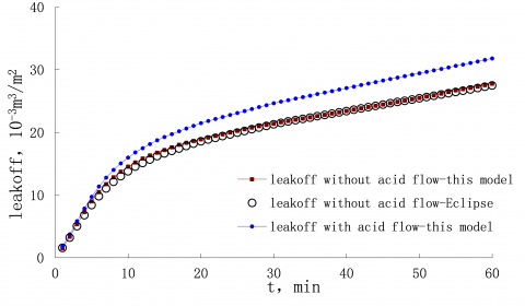
In this paper, the above numerical model was adopted to simulate the acid leakoff in Puguang naturally fractured carbonate gas reservoir, and compared with the results of Eclipse. The data on the gas reservoir are listed in Table 1, where L is the distance hydraulic fracture to the reservoir boundary, and W is the distance between the two main natural fractures (which depends on the natural fracture density). The dimension of the numerical model was 100m*10m. The simulations were carried out with and without considering the acid effects like acid flow, acid-rock reaction and fracture width variation.
The simulation results in Figure 3 show that the proposed numerical model output comparable results to those of the Eclipse prediction. For the numerical model, the acid leakoff predicted considering the acid effects deviated from that predicted without considering such effects by 11.4%. Thus, the acid effects should not be ignored in the leakoff calculation for naturally fractured carbonate gas reservoirs. After considering these effects, the prediction of the numerical model agrees well with Eclipse prediction. To sum up, it is confirmed that the numerical model is a feasible way to predict the acid leakoff in naturally fractured carbonate gas reservoirs.
Table 1. The data on Puguang naturally fractured carbonate gas reservoir
|
Parameter |
Value |
Parameter |
Value |
|
Hydraulic fracture pressure, Pa |
70×106 |
Reservoir pressure, Pa |
55×106 |
|
Fracture system permeability, μm2 |
0.03 |
Reservoir Fluid compressibility, Pa-1 |
1×10⁻⁸ |
|
Matrix system permeability, μm2 |
0.002 |
Matrix system porosity compressibility, Pa-1 |
1×10⁻⁹ |
|
Fracture system porosity |
0.003 |
Fracture system porosity compressibility, Pa-1 |
1×10⁻⁹ |
|
Matrix system porosity |
0.05 |
Acid compressibility, Pa-1 |
1×10⁻¹⁰ |
|
FractureⅠwidth, μm |
50 |
Acid Viscosity, Pa·s |
0.03 |
|
Fracture Ⅱwidth, μm |
50 |
Acid concentration, wt% |
15% |
Figure 3. Daily gas production and cumulative gas production predicted by Eclipse and our model
3.1 Effect of acid concentration on leakoff
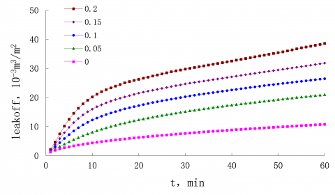
Figure 4. The effect of acid concentration on acid leakoff
The time variation in the acid leakoff at different acid concentrations is presented in Figure 4, where the acid concentration of 0% is a non-reactive liquid. As shown in the figure, the acid leakoff increased with the acid concentration. At 60min, the acid leakoff at the acid concentration of 20% was about four times higher than that of the non-reactive liquid, and twice that at the 5% concentration. Therefore, the acid concentration is positively correlated with the rock dissolution ability of the acid as well as the fracture width. A wider fracture has less resistance to the acid flow, providing a highly permeable channel for acid leakoff. As a result, the acid leakoff is increased in the naturally fractured carbonate gas reservoir.
Figure 5. The effect of acid concentration on acid leakoff rate
Figure 5 depicts the time variation in the acid leakoff rate at different acid concentrations. It can be seen that the leakoff rate clearly increased with the acid concentration. When the acid concentration was above 10%, the acid leakoff rate firstly grew, then decreased for a few minutes, and finally remained stable after 20min. When the acid concentration was below 5%, the leakoff rate exhibited a declining trend with no increase in the initial phase. This trend bears resemblance to that of acid flow rate in homogeneous sandstone. When its concentration is above a threshold, the acid will react with the rock on fracture surface, such that no filter cake will form on that surface. The acid leakoff is controlled by both acid viscosity and compressibility. In the initial phase, the main natural fractures widen and the seepage resistance reduces in acid-rock reaction, pushing up the leakoff rate. After a few minutes, compressibility starts to act as the dominant controlling factor of acid leakoff. Under the effect of compressibility, the leakoff rate started to decline although the leakoff acid continued to suppress the seepage resistance. The above results show that the effect of acid concentration is not negligible in the calculation of acid leakoff.
3.2 Effect of acid viscosity on leakoff
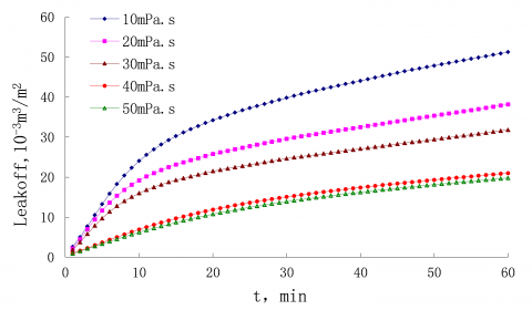
The time variations in acid leakoff and acid leakoff rate at different acid viscosities are respectively recorded in Figure 6 and Figure 7. As shown in the figures, both leakoff and leakoff rate decreased with the growth in acid viscosity. At 60min, the leakoff of the 10mPa·s acid was twice that of the 50mPa·s acid. When the acid was very viscous (e.g. 50mPa·s), the acid solubility was overshadowed by the viscosity, and the leakoff rate did not increase in the initial phase. When the acid was not viscous (e.g. 10mPa·s), the leakoff rate increased greatly in the initial phase, an evidence of obvious dissolution effect. These results show that the acid viscosity should be kept high during the acid fracturing of naturally fractured carbonate gas reservoir. Contrary to acid-rock reaction, the acid viscosity enhances the leakoff resistance and suppresses the leakoff. However, the high cost of high-viscosity acid calls for a reasonable setting of the viscosity value. For example, an additive could be used to maintain the viscosity of the acid to control the leakoff.
Figure 6. The effect of acid viscosity on acid leakoff
Figure 7. The effect of acid viscosity on acid leakoff rate
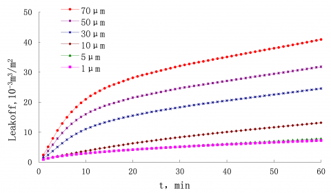
3.3 Effect of main natural fracture width on leakoff
Figures 8 and 9 describe the time variations in acid leakoff and acid leakoff rate at different widths of main natural fractures. In general, both acid leakoff and acid leakoff rate increased with the fracture width.
As shown in Figure 8, a narrow fracture, i.e. a micro-fracture (<5μm), had little impact on acid leakoff, while a wide fracture (>10μm) increased the leakoff significantly. The 70μm wide fracture led to an acid leakoff four times higher than that of a 10μm wide fracture.
As shown in Figure 9, the leakoff rate increased with the width difference between main natural fractures in the initial phase, and started to decline after 20min due to the strong effect of compressibility in the later phase. The initial growth was obvious for wide main fractures and not seen in micro-fractures. At the presence of wide natural fractures, the acid can enter the formation directly, bypassing the matrix part. Therefore, the wide natural fractures are the main cause of acid leakage in naturally fractured gas reservoirs.
Figure 8. The effect of the main natural fracture’s width on acid leakoff
Figure 9. The effect of the main natural fractures width on acid leakoff rate
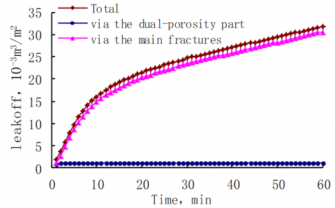
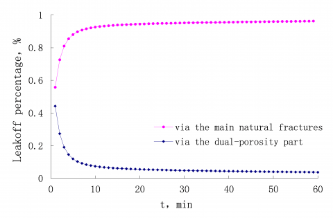
3.4 Effects of main natural fractures and dual-porosity part on leakoff
Figure 10. The effect of the main natural fractures on acid leakoff
Figures 10 and 11 respectively display the time variations in acid leakoff and acid leakoff ratio in main natural fractures and dual-porosity part. It can be seen that the main natural factures contribute most of the acid leakoff (>80 %). As shown in Figure 10, the two parts had similar amounts of leakoff in the initial phase; after a few minutes, the main natural fractures began to dominate the leakoff, as over 80 % of acid was leaked through these fractures. The acid leakoff in naturally fractured carbonate gas reservoirs happens either through the main natural fractures or through the dual-porosity part. Due to acid dissolution, the proportion of leakoff through the main natural fractures will increase rapidly, while that through the other part plunge. Hence, the acid leakoff in naturally fractured carbonate gas reservoirs is mainly influenced by natural fractures.
Figure 11. The effect of the dual-porosity part on acid leakoff
This paper designs a comprehensive dual-porosity gas/acid flow model based on the intrinsic properties of naturally fractured gas carbonate reservoirs, and develops a numerical simulator for this model. The numerical simulator was verified through comparison with Eclipse, and applied to simulate an actual naturally fractured gas carbonate reservoir. The following conclusions were drawn from this research:
(1) Unlike the traditional non-reactive liquid leakoff, the acid leakoff occurs as the acid reacts with the rock on the surface of natural fractures, making it hard for the filter cake to form. The acid leakoff is controlled by acid viscosity and compressibility. In the initial phase, the acid seepage resistance was reduced and the leakoff rate increases due to the acid-rock reaction. After a few minutes, the compressibility became the dominant controlling factor of the leakoff. Under the effect of compressibility, the leakoff rate started to decline although the leakoff acid continued to suppress the seepage resistance. When the acid solubility was not obvious (concentration 5 %, viscosity>mPa·s), the leakoff rate did not increase in the initial phase, and the trend is similar to that in homogeneous sandstone.
(2) The acid concentration is positively correlated with the rock dissolution ability of the acid as well as the fracture width. A wider fracture has less resistance to the acid flow, providing a highly permeable channel for acid leakoff. Hence, acid concentration is a major impactor of acid leakoff. In general, the acid leakoff at the acid concentration of 20 % was about four times higher than that of the non-reactive liquid (concentration 0 %). The effect of acid concentration must be considered in the calculation of acid leakoff.
(3) The acid viscosity should be kept high during the acid fracturing of naturally fractured carbonate gas reservoir. Contrary to acid-rock reaction, the acid viscosity enhances the leakoff resistance and suppresses the leakoff. However, the high cost of high-viscosity acid calls for a reasonable setting of the viscosity value. For example, an additive could be used to maintain the viscosity of the acid to control the leakoff.
(4) When the natural fractures were narrow, the acid-rock reaction had little impact on acid leakoff, and the acid leakoff rate was the same as that in the sandstone, with no initial growth in the leakoff rate. At the presence of wide natural fractures, the acid can enter the formation directly, bypassing the matrix part. Therefore, the wide natural fractures are the main cause of acid leakage in naturally fractured gas reservoirs.
(5) The acid leakoff in naturally fractured carbonate gas reservoirs happens either through the main natural fractures or through the dual-porosity part. Due to acid dissolution, the proportion of leakoff through the main natural fractures will increase rapidly, while that through the other part plunge. Hence, the acid leakoff in naturally fractured carbonate gas reservoirs is mainly influenced by natural fractures.
The authors gratefully acknowledge the sponsor of the Project supported by The National Science and Technology Major Project of China, No. 2017ZX05035.
[1] Economides MJ, Nolte KG. (1989). Reservoir stimulation. Englewood Cliffs, New Jersey: Prentice Hall: 12-31. https://doi.org/10.1002/9780470650684.ch1
[2] Carter E. (1957). Optimum fluid characteristics for fracture extension. American Petroleum Institute: 261-270.
[3] Mitchell SL, Kuske R, Peirce AP. (2007). An asymptotic framework for finite hydraulic fractures including leak-off. SIAM Journal on Applied Mathematics 67(2): 364-386. https://doi.org/10.1137/04062059x
[4] Xu B, Hill A, Zhu D, Wang L. (2011). Experimental evaluation of guar-fracture-fluid filter-cake behavior. SPE Prod. Oper. 26: 381-387. http://doi.org/10.2118/140686-PA
[5] Yi T, Peden JM. (1994). A comprehensive model of fluid loss in hydraulic fracturing. Old. Prod. Facil. 9: 267-272. http://doi.org/10.2118/25493-PA
[6] James LR. (2000). Impact of Natural Fractures in Hdraulic Fracturing of Tight Gas Sands. SPE59540. http://doi.org/10.2118/59540-MS
[7] Li YM, Guo J, Zhao JZ, Wu XQ, Li Y. (2004). New model for fracturing fluid leakoff in naturally fractured gas fields and its application. Petroleum Exploration and Development 31: 120-122.
[8] Guo J, Liu Y. (2014). Opening of natural fracture and its effect on leakoff behavior in fractured gas reservoirs. Journal of Natural Gas Science and Engineering 18: 324-328. https://doi.org/ 10.1016/j.jngse.2014.03.013
[9] Fan Y, Economides MJ. (1995). Fracturing fluid leakoff and net pressure behavior in frac & pack stimulation. SPE-29988-MS, International Meeting on Petroleum Engineering, 14-17 November, Beijing, China. http://doi.org/10.2118/29988-MS
[10] Yew CH, Ma MJ, Hill AD. (2000). A Study of Fluid Leakoff in Hydraulic Fracture Propagation. SPE-64786-MS, International Oil and Gas Conference and Exhibition in China, 7-10 November, Beijing, China. http://doi.org/10.2118/64786-MS
[11] Coulter AW, Crowe CW, Barrett ND. Miller BD. (1976). Alternate Stages of Pad Fluid and Acid Provide Improved Leakoff Control for Fracture Acidizing. SPE-6124-MS, SPE Annual Fall Technical Conference and Exhibition, 3-6 October, New Orleans, Louisiana.
[12] Crowe CW, Hutchinson BH, Trittipo BL. (1989). Fluid-loss control: the key to successful acid fracturing. SPE Production Engineering 4(3): 215-220. http://doi.org/10.2118/16883-PA
[13] Guo T, Li Y, Ding Y, Qu Z, Zhai N, Rui Z. (2017). Evaluation of acid fracturing treatments in shale formation. Energy & Fuels 31(10): 10479-10489. http://doi.org/10.1021/acs.energyfuels.7b01398
[14] Daccord G, Touboul E, Lenormand R. (1989). Carbonate acidizing: Toward a quantitative model of the wormholing phenomenon. SPE Production Engineering, 63-68. http://doi.org/10.2118/16887-PA
[15] Hung KM, Hill AD, Sepehrnoori K. (1984). A mechanistic model of wormhole growth in carbonate matrix acidizing and acid fracturing. Journal of Petroleum Technology 36: 2055-2069. http://doi.org/10.2118/16886-PA
[16] Nierode DE, Kruk KF. (1973). An evaluation of acid fluid loss additives retarded acids, and acidized fracture conductivity. SPE-4549-MS, Fall Meeting of the Society of Petroleum Engineers of AIME, 30 September-3 October, Las Vegas, Nevada. http://doi.org/10.2118/4549-MS
[17] Crowe CW, Hutchinson BH, Trittipo BL. (1989). Fluid-loss control: the key to successful acid fracturing. SPE Production Engineering 4(3): 215-220. http://doi.org/10.2118/16883-PA
[18] Settari A. (1993). Modeling of acid-fracturing treatments. SPE Production & Facilities, 30-38. http://doi.org/10.2118/21870-PA
[19] Hill AD, Zhu D, Wang YM. (1995). The effects of wormholing on the fluid-loss coefficient in acid fracturing. SPE Production & Facilities, 257-263. http://doi.org/10.2118/27403-PA
[20] Siemers J, Dreybrodt W. (1998). Early development of karst aquifers on percolation networks of fractures in limestone. Water Resources Research 34(3): 409-419. https://doi.org/10.1029/97WR03218
[21] Dong C, Hill AD, Zhu D. (1999). Acid etching patterns in naturally-fractured formations. SPE-56531-MS, SPE Annual Technical Conference and Exhibition, 3-6 October, Houston, Texas. http://doi.org/10.2118/56531-MS
[22] Warren JE, Root PJ. (1963). The behavior of naturally fractured reservoirs. Society of Petroleum Engineers: 245-255. http://doi.org/10.2118/426-PA
[23] Dranchuk PM, Abou-Kassem H. (1975). Calculation of Z factors for natural gases using equations of state. Journal of Canadian Petroleum Technology 14(3); PETSOC-75-03-03. http://doi.org/10.2118/75-03-03
[24] Lee AL, Gonzalez MH, Eakin BE. (1966). The viscosity of natural gases. Journal of Petroleum Technology 18(8): 997-1000. http://doi.org/10.2118/1340-PA