OPEN ACCESS
To date, accumulated large amount of experimental and theoretical data on the thermal hydraulics dimpled surfaces that demonstrate their high efficiency. However, the extent of the use of these surfaces in the industry far below their potential. This paper discusses the idea of using these surfaces to increase the efficiency of heat exchangers with a high coefficient of fins (e.g., air coolers). This makes it possible to achieve good results with minimal pressure loss increase and admit to widen practical use of such artificial roughness. Importantly, these reliefs provide heat transfer enhancement both on the side with dimples and on the side with protrusions. Most practically suitable for industrial implementation are tube-and-plate heat exchangers with continuous fins and new type of finned tubes − flat-oval tubes with partial finning. When using plane fins with dimples we can substantially increase efficiency if heat transfer intensity on shell side is not high. So we can bring the level of compactness of shell-and-tube heat exchangers up to values characteristic for the plate heat exchangers. Results of calculations showed a possibility of efficiency increase due to dimples to 60-70%.
plate-and-tube heat exchanger, heat transfer enhancement, dimples, plane fins
As it is known, the first experimental results which showed the dimpled surfaces efficiency were obtained more than thirty years ago. However, the extent of implementation of these surfaces in the practice of the heat transfer equipment production is not adequate to the such real benefits that can be obtained due to their broad introduction. Especially strange to see this against the background of wide scale experimental and theoretical studies of their thermal-hydraulic properties in the world. Somewhere around 10 years ago, it was suggested that dimpled and annular (or spiral) rolling can be attributed to the same class, satisfying the following definition: the artificial roughness created by wall pressure deformation – ARPD [1]. Over the past 15-20 years a large volume of experimental and theoretical investigations of heat transfer and hydraulic of channels with dimpled walls was performed. This allowed to consider in this paper one of the possible ways to widen the use of dimpling in heat exchangers.
A parallel study of two mentioned types of relief was performed by V.I.Terekhov and his co-workers. But instead of rolling case they investigated mainly her flat analog - the trench.. His work contains a comparison of these two cases, the flow structure and the thermal and hydraulic characteristics. Note that both reliefs mentioned have sufficiently high thermal-hydraulic performance. In this paper we will not discuss in detail the quantitative results of such comparisons, because its main purpose is different. We are going to compare the feasibility of using these reliefs to create heat exchangers. We first note the following fact. In the forming of such surface reliefs bilateral intensification occurs - on the one side in the form of recesses and on the other side in the form of protrusions.
At the time two teams of authors suggested two types of reliefs for the heat transfer enhancement in the channels. They moved, so to speak, from different sides. Scientists from the MAI (Moscow aviation institute) used annular rolling of tube outer surface. But they focused on the effect produced by the system of annular protrusions formed at the same time on the inner surface of the tube [2]. Initiators of dimpled surfaces [3] used for the enhancement of heat transfer system of dimples on the outer surface. Its formation on the inner surface using initially round smooth tubes would be a difficult task. Therefore most of the experiments were carried out with the dimples in the annular channels. On the other hand, in the case of use for dimpling flat surfaces instead of cylindrical surfaces, the problem becomes quite simple. In the second half of 1990th CKTI and Podolsk Engineering Plant carried out together a work consisting of three stages. First, the plant designed a method of metal sheet dimpling. Then were produced welded pipes in two versions - with dimples and protrusions inside, which were tested on the stand in CKTI.
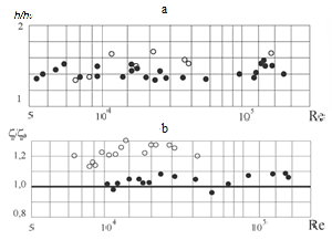
Figure 1. Experimental data of [4] on heat transfer (a) and hydraulic resistance (b) for dimpled tube with two variants of dimpling • – dimples on inner surface; 。– protrusions on inner surface
Results of these tests [4] were repeatedly demonstrated earlier. This obviously shows the following. If the depth of the dimples is small compared to the diameter of the pipe, the heat transfer enhancement for both options is very close. It is very important that the pressure loss for protrusions is only about 20% higher than the pressure loss for dimples. Regarding the dimples, the pressure loss for them were in the range (1.0 - 1.1) of losses in smooth tube. Growth of heat transfer was in the range (1.4 - 1.6) of a smooth tube. Finally, the last stage of work at the plant has been made gas-gas heat exchanger of similar pipes, which tests has shown results which correspond to the calculations made using experimental CKTI data [5].
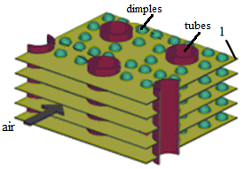
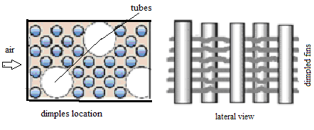
It is necessary to mark mentioned above important factors determining interest to dimpling of flat surfaces. Dimpling is significantly easier to implement for flat walls rather than cylindrical ones. On the other hand, in so-called continuous fins are used quite frequently. A fragment of such heat exchanger, which is called plate-and-tube heat exchanger (PTHE) with dimples is shown in figure 2.
Figure 2. Plate-and-tube heat exchanger, studied by CFD methods in [6]: 1 – dimpled fin
Its thermal and hydraulic characteristics were investigated by CFD methods in [6].
Some results of this work will be considered below. We remind that the amount of heat transferred through the flow fins, approximately given by following well known expression
Qp = h J1Fp*Е, (1)
where E = $\frac{[\text{th}(l/\delta )\sqrt{2Bi})]}{(l/\delta )\sqrt{2Bi}}$ – fin efficiency;
Bi = hd/l – Bio number; d – fin thickness; Fp* – fin effective cross section, which takes into account variable cross section along the radius; l – fin height; h – fin heat transfer coefficient.
In this case, clarification of this relationship does not make sense, though, if l is much larger than radius of the pipe, the problem of Fp* definition becomes much more complicated. Figure 4 shows a fragment of the fin structure. To simplify the analysis of the hexagonal fin belonging to the central tube is replaced by that of circular edge, the same area. Its outline is painted red. The value l corresponds to the difference between the radii of the contour and the tube. Small circles marked dimples, if any. Let us now consider the structure of the equation (1). Obviously, if the complex x = $\frac{l}{\text{ }\!\!\delta\!\!\text{ }}\sqrt{\frac{2h\text{ }\!\!\delta\!\!\text{ }}{\text{ }\!\!\lambda\!\!\text{ }}}$ much less than unity, it is obvious that in accordance with the limiting expression to the hyperbolic tangent we obtain the equation
Qp = h J1Fp* (2)
This means that the fin actually has a temperature equal to the temperature of the surface of the tubes and heat removal from the edges is proportional to the increase in the coefficient of heat transfer from the surface of the ribs. It is therefore reasonable, using intensified fins at the same time to reduce the pitch of the tube bundle, which would make the heat exchanger more compact. It is logical to assume that in the above-described structure, plate-tube heat exchanger pipe affect flow over dimples on the continuous fins located in their vicinity, in fact in a slot channel, this impact can be positive and may depend on the relative position of tubes and dimples.
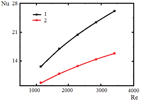
It is known from [7], where the transition was investigated experimentally by infrared thermography and numerical simulation RANS intensification of heat transfer in a slot channel when placed on one of its baffle walls, consisting of a combination of spherical dimples a rectangular projection and cylindrical pin fins. But this work does not attempt to determine the optimal configuration of the mutual arrangement of the recesses, protrusions and edges, but noted their positive mutual influence on heat transfer in a channel. Some results of numerical study heat transfer and hydrodynamics of such heat exchanger obtained in [6] are shown in fig.5. For dimpled fins and a one row of tubes authors obtained Nu number depending on Re number for smooth and dimpled fins ( see fig.5). At Re = 3500 we have a growth of 1.67 times. This value increases relatively fast with Re number growth. Of course, this value is not equal to the increase in heat transfer coefficient for the heat exchanger as a whole. The latter will be determined by a number of parameters, which include the first fin coefficient ratio of heat transfer coefficients within the tubes and the fins on the surface and edges of the cross section geometry in combination with its heat conductivity.
Figure 3. Heat transfer for the case of smooth and dimpled fins for 2 rows of tubes: 1 – dimpled tubes; 2 - smooth tubes. CFD results [6]
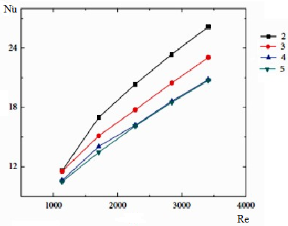
Figure 4. Nu number for rows # 2. 3, 4 (CFD results [6])
The results presented here are somewhat surprising at first sight. It is known that at least for the case of smooth round fins, heat transfer tends to grow with number row of tubes and in any case, does not fall with an increase with row of tubes number. Unfortunately, this is the only work with such result concerning this particular topic, which we were able to find. For such heat exchangers are no calculation methods and formulas usually used for bundles of finned tubes.
And in addition the reliability of such calculations could be assigned into question because of opposite influence of row number. We will return to this problem below.
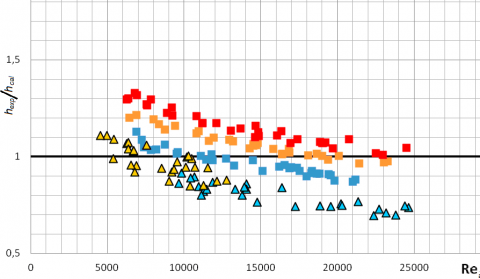
Recently in CKTI were conducted experiments with real spesiments of such heat exchangers. These tested heat exchangers had two types of continuous fins - smooth and wavy. Even for the smooth fins of the use of the above recommendations led to a marked discrepancy with the experimental results, and, as quantitative as well as qualitative. Therefore, amendments have been introduced, which are naturally suited only for a tested group of channels. Some of such results are presented in figure 5. Ordinate axis in figure 5 [8] is the ratio of experimental heat transfer values hex and calculated hcal values by the formulas for tube bundles with round fins. Upper group of experimental points (quadratic) – continuous fins with wave enhancing relief, lower group (triangular) – smooth continuous fins.
Figure 5. Results of CKTI heat transfer experiments
These facts led us to consider more carefully the pre-existing recommendations for the heat transfer in the tubular-plate heat exchangers. The best known, depending suggested Webb [9] and included in the well-known reference book Sekulic and Shah [10]. These recommendations are as follows
j4=0.14Red0.328(Xt/X1)0.502(s/d0)0.031 (3)
For the number of tube rows N from 1 to 3, the j factor is lower and is given by:
jN/ j4 = 0.991[2.24Red-0.092(N/4)0.031]0.607(4-N) (4)
Note that the authors use the heat from the dependence on the number of rooms, similar to those used in the recommendations [19] for bundles of finned tubes. We have already mentioned that such an attempt is made to the processing of the experimental data obtained in CKTI, it was unsuccessful. It was possible to summarize the test data only by using the exponent with the number Re, close to 0.5.
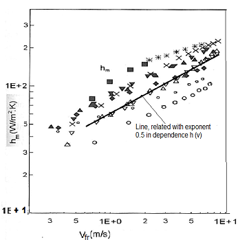
Figure 6. Illustration of heat transfer dependence on velocity ([18] points nomenclature is omitted)
It should be noted that for the same range of numbers Re in later work involving R. Webb [18] observed approximately the same degree of performance. (See. figure 6). This fact is confirmed by a fragment of the picture with the experimental data of [20]
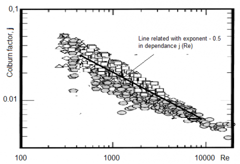
Similar results were actually obtained in [13]. Exceptional bulkiness correlations proposed in this paper does not allow to visually verify the presence of such a relationship. However, if you just refer to the experimental points in Figure 8 of the database used by the authors, it becomes obvious. We note that the slope is closed to 0.5, because the heat transfer is not used, and the Colborn number.
Figure 7. Illustration of Colborn number dependence on Re number ([12] points nomenclature is omitted)
Nomenclatures of experimental points in pictures 8, 9 are omitted, because we consider common tendency only.
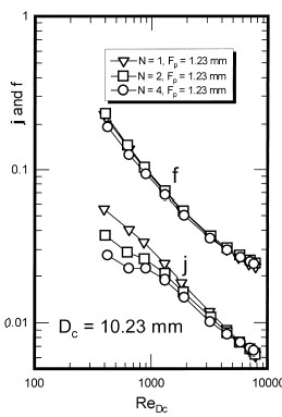
The second problem is heat transfer dependence on row number. Traditionally common opinion is: heat transfer grows with row number rise up to approximate N = 4. Such situation takes place both for bundles of plain tubes and finned tubes. This opinion is implemented in formulas (3, 4). We have seen data of CFD calculations (figure 4) where opposite results were obtained. But some experimental data for row number effect on heat transfer for PTHE show that mentioned picture isn’t takes place.
Figure 8. Demonstration of absence heat transfer growth with row number
Next picture is taken of ref. [13]. One can see that inverse stratification take place at small Re numbers and practically absence for more Re numbers. Thus, for a more reliable analysis of the dependence of heat transfer on the number of rows, additional studies of this dependence are needed. The same problem also arises for the exponent in the power-law dependence of the heat transfer on the number Re. It changes in the range 0.511 – 0.759 [14]. Significant difficulties also arise with taking into account the input effects.
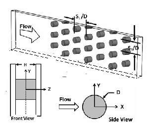
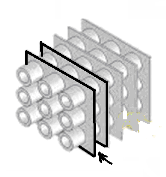
Further information connected with problem under consideration was got unexpectedly from investigation on pin-fin heat transfer enhancement [14, 15]. The configuration of the experimental plots used for this purpose proved to be very similar to the one that we planned to use for research on the issue intensified plate-and-tube heat exchanger. The point is, the flat channel with pin fins corresponds to a single channel in PTHE because continuous fins form just such channels. Simple scheme of such channel is presented in figure 9.
Figure 9. Flat channel with pin fin enhancement
Figure 10. Fragment of PTTE with same subchannel
Parts of tubes between plain fins are corresponded pin fins channels. Because heat transfer in tubes is much higher than in the gas flow we can regard these parts as isotherrmic. So we can use the same approach as for fin pin case.
Interesting that in ref. [14-16] for data processing not the same approach was used than in ref. [11-13] Four Nu numbers are considered – Nu0, Nud,endwall, Nud,.pin.. and Nud.
Nud,endwall is related with heat transfer from plain surfaces, Nud,.pin..- with pin surfaces and Nud.is related with total effect. Nu0 – Nu number for channel without fins. For Nud formulae is used which account parts of total surface
Nud = Nud,endwall,(Apin /Atotal) + Nud,.pin (Apin /Atotal)
where Ai – сorresponding areas.
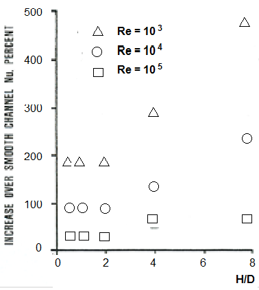
It is important that for fin pin channels experimental data are obtained for small fin pin aspect ratio up to h/d = 0.5. These results are presented in figure 11.
Figure 11. Heat transfer enhancement for flat channel surface with cylindrical inserts
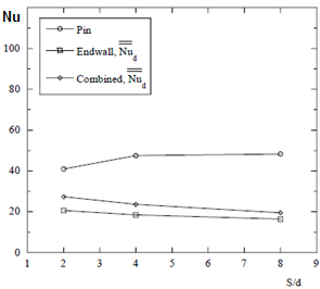
In figure 11 (ref [16]) we can see relative heat transfer growth in comparison with smooth flat channel. It is very interesting to see that relative heat transfer enhancement for aspect ratio (H/D) at least less 2 don’t depend on H/D. This picture gives a possibility to observe qualitative dependence of heat transfer enhancement value on H/D and Re. In particular one can see, that for Re >104 effect of pin fin usage is decreased rapidly. Next picture shows different dependence pin and endwall heat transfer on transversal pitch.
Figure 12. Plot showing the dependency of Nud on S/d at a nominal Reynolds number of Red = 5000
Since the proposed methods have no sufficient experimental confirmation we're going to continue work in two directions. Firstly, using the experience of CFD simulation flat dimpled channels and cross-flow pipe bundles to investigate a single flat dimpled channel where cylinder or several cylinders are installed. At the same time, we can get some picture of the interaction of the two sources of turbulence - aft zone of the streamlined cylinder and dimple ensemble.
First, we note that the principal goal of working is to provide fin-and-tube heat exchanger, ensuring the fulfillment of two requirements - approach the level of compactness to the plate heat exchanger while maintaining greater simplicity of construction and significant growth in heat exchange efficiency for low thermal conductivity heat transfer agents. Such a situation may for example occur when the steam is overheated by convection or condensation medium with higher temperature or convective cooling gaseous fluid. In order to describe more specifically the positive features of the proposed approach to the heat exchanger efficiency improvement, we use primarily a unique experimental material to study the flat dimpled channels obtained in [17-19]. It allows to perform rather convincing preliminary evaluations of the PTHE effectiveness with continuous dimpled fins for which we use the abbreviation PTHED.
It should also be noted that very significant fact in ref. [17] was set. When two dimpled surfaces of flat channel are situated too close to each other heat transfer intensity begins to fall. So it is recommended not to choose bilateral dimpling with the relative distance between the plates less than 0.35.
Figure 13. Simplified fragment of proposed heat exchanger constraction
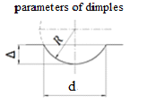
Figure 14. Form of single dimple
In assessing the efficiency, we will proceed from the fact that the described embodiment of the growth of heat transfer compared to a smooth surface, corresponds to a resistance increase, surpassing its no more than 10%. For such estimation bundle pipe diameter D = 20 mm and relative pitch S/D ~ 2 has been selected and the size of the finning ratio ~10-15. The thickness of the ribs varied from 1 to 2 mm and the pitch of fins varied from 3 to 5 mm.
For a preliminary assessment of thermal-hydraulic properties of continuous fins with dimples formulas proposed in ref. [6] were used.
Nu = Nu0 [1 + 4.4 (Δrel f)0,8 / hrel] (4)
ζ/ζ0= l+26(Dr el f)1. 1 (5)
In these formulas f - density of dimpling, d - diameter of dimple; Δrel = Δ/d – relative depth of dimple, hrel = h/d –relative distance between plates, ζ – drag factor.
Index 0 refers to a smooth channel.
Estimates show that even when using an austenitic stainless steel, which is one of the structural materials with low heat transfer ability we achieve fin efficiency close to unity. With this approach, it is important that the heat exchange surface of the coolant with the low heat transfer properties substantially greater than that for a highly efficient heat transfer medium flowing in the tubes. Dimpling utilization increases additionally its effectiveness, but does not change the qualitative nature of heat transfer.
One can also consider the option of a phase transition of the coolant inside the tubes. But, of course, it is necessary to perform calculation and experimental studies to create a modern calculation method which provides the ability to optimize design solutions. In the course of such investigations some improvement of dependencies used for heat transfer and hydraulic resistance may be achieved. It is necessary to take into account the opportunities of use of CFD methods, which over the last 10-20 years made significant methodical and technology progress. In particular, this applies both to specific dimpled surfaces and to eddy currents in general [20-21]. Therefore, you can count on the fact that much of the work on the creation of the mentioned calculation method can be performed more rapidly by reducing the volume of experimental work.
Such an approach would be consistent with modern trends in the formation of CFD software, which have been formulated by one of "fathers" of modern computational fluid dynamics D.B. Spalding in the lection at the 12th International Conference on Heat Transfer in Grenoble. The essence of his proposal was to combine in software thermal hydraulic, structural and strength problems.
It is interesting to get by calculation the picture of the interaction of the two sources generating vortices in the stream - flow over transverse bundles fragments of tubes and flow over artificial roughness elements, consistent with the experiment.
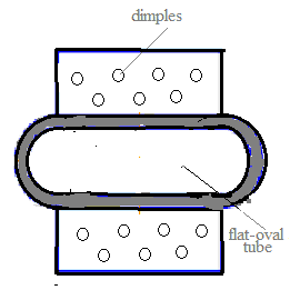
At the same time, we intend to consider additional option, which was recently proposed and investigated in Ukraine by E. Pismenny [22]. Its design is shown in figure 15. This is a new type of finned tubes − flat-oval tubes with partial finning.
In ref. [22] their main characteristics are described. The results of comparison of these tubes with other types of finned surfaces are given. It was shown that introduction of the new finned tubes will lead to considerable economy of material and energy resources.
Figure 15. Flat-oval finned tube with partial finning
What concerns of design considered before that preliminary calculations showed that the surface area for them per unit volume in the range of 300 - 600 1/m can be easily achieved, which corresponds to actual values for plate heat exchangers. But, at sucking, we did not yet have the opportunity to conduct an experimental study of the proposed construction.
So, in this study we demonstrated the ability to use advanced conventional heat exchanger circuit for a large part of the range of media used in achieving high levels of compactness. The proposed approach allows for a number of situations in a significant degree to bring closer efficiency shell and tube heat exchangers to the plate in terms of use the device volume while maintaining its simpler internal structure.
It is important to note that the peculiarity of proposed idea using the dimpling differs in principle from trying to insert structure of plate heat exchanger in a hard shell to increase the permissible level of pressure as it is done in a relatively recently appeared shell-and-plate heat exchangers.
Due to the intensive development of CFD methods it is possible to rely on the fact that much of the work on creation of the calculation method for such heat transfer units and their optimization could be done fairly quickly with decreasing volume of experimental work.
Вut additional experiments will be needed too, because even for more simple case without dimples significant scatter of the experimental results takes place.
Authors are grateful to V. Lychakov for providing information about the results of the experimental study on the heat transfer plate-and-tube heat exchangers
|
Q |
heat flux, W |
|
h |
heat transfer coefficient, W/(m2K) |
|
k |
thermal conductivity, W/( mK) |
|
Nu |
Nusselt number , dimensionless |
|
Re |
Reynolds number, dimensionless |
|
Bi |
Bio number, dimensionless |
|
a |
thermal diffusivity, m2/ s |
|
l |
fin height (conditional), m |
|
F |
cross section, m2 |
|
E |
fin efficiency |
|
N |
row number/ number of rows |
|
j |
Colborn number, j = Nu/Re/Pr1/3 |
|
D |
tube or pin fin diameter, m |
|
V |
Velocity, m/s |
|
X S |
longitudinal tube pitch, m transverse tube pitch, m |
|
d |
diameter of dimple “print”, m |
|
R |
dimple radius, m |
|
Greek symbols |
|
|
$\delta$ |
fin thickness, m |
|
$\Delta$ |
dimple depth, m |
|
$\vartheta$ |
dimensionless temperature K |
|
$\lambda$ |
Heat conduction coefficient, W/(mK) |
|
Subscripts |
|
|
f |
fin |
|
rel |
relative |
|
SUP |
superheated |
|
SUB |
subcooled |
|
Abbreviations |
|
|
CKTI |
Polzunov institute |
|
PTHE |
plate-and-tube heat exchanger |
|
PHTED |
plate-and-tube heat exchanger with dimpled plates |
[1] Gotovsky M., Isaev S. (2010). Heat transfer enhancement by artificial roughness at Reynolds numbers related with laminar and transitional regimes for high-viscous liquids, 14 International. Heat Transfer Conf., Washington, IHTC 14-22303. (CD).
[2] Kalinin E.K., Dreitser G.A., Yarkho S.A. (1990). Heat transfer enhancement in channels, Mashinostroenie, Moscow, p. 208. (in Russian).
[3] Kiknadze G., Gachechiladze I, Alekseev A. (2005). Self-organization of tornado-like jets in flows of viscous media and heat-mass transfer enhancement accompanying this phenomenon MPEI, Moscow, p. 84. DOI: 10.24160/1993-6982
[4] Gotovsky M., Fokin B., Belenkii M. (2004). Heat transfer and hydraulic resistance at flow in round tube enhanced by regular system of spherical dimples and spherical protrusions, Trudi CKTI, No. 293, SPb, pp. 36-48. (in Russian)
[5] Shrader I., Dashchan A., Gotovsky M. (1999). Intensified tube air reheaters, Thermal Engineering, Vol. 46, No. 6, pp. 54-57. DOI: 10.24160/1993-6982
[6] Wu X.H., et al. (2011). Numerical study on the effect of tube rows on the heat transfer characteristic of dimpled fins, Hindawi Proc of gas turbine blade, ASME Paper. GT2011-45356.
[7] Murata A., et al. (2011). Heat transfer enhancement due to combination of dimples, protrusions, and ribs in narrow internal passage of gas turbine blade ASME Paper. 2011. GT2011-45356.
[8] Lychakov V. (2016). Experimental study of thermal hydraulic characteristics of heat exchangers with developed external surface in NPP safety systems, PhD dissertation Abstract, Russian Federation, (in Russian).
[9] Webb R.L. (1994). Principles of Enhanced Heat Transfer, John Wiley, New York. ISBN-10: 1591690145.
[10] Shah R.K., Sekulich D.P. (2007). Fundamentals of Heat Exchanger Design, Wiley Online Library, ISBN 0-471-32171-0.
[11] Wang H.C., Webb R.L. (1998). Performance comparison of enhanced fin geometries used in fin-and-tube heat exchangers, 11 International Heat Transfer Conf., Kuongju, Vol. 6, pp. 273-278.
[11] Wang C.C., Chi K.Y., Chang C.J. (2000). Heat transfer and friction characteristics of plain-and-tube heat exchangers, part II: Correlation, Int. J Heat & Mass Transfer, Vol. 43, pp. 2693-2700.
[12] Wang C.C., Chi K.Y. (2000). Heat transfer and friction characteristics of plain-and-tube heat exchangers, part I: New experimental data, Int. J Heat & Mass Transfer, Vol. 43, pp. 2681-2691.
[13] Lyall Michael E. (2006). Heat transfer from low aspect ratio pin fins, MS dissertation, Virginia Polytechnic Institute and State University, Blacksburg, VA.
[14] Lawson S.A., Thrift A.A., Thole K.A., Kohli A. (2011). Heat transfer from multiple row arrays of low aspect ratio pin fins, Int. J. Heat & Mass Transfer, Vol. 54, pp. 4099-4109. DOI: 10.1016/ijheatmasstransfer.2011.04.001
[15] Armstrong J., Winstanley D. (1988). A review of staggered array pin fin heat transfer for turbine cooling applications, ASME Journal of Turbomachinery, Vol. 110, pp. 94-103. DOI: 10.1115/1.3262173
[16] Anurov Y. (2005). Effective methods of heat enhancement in cooling systems blading transfer of high temperature gas turbines, Doctor of science dissertation Abstract. (in Russian).
[17] Anurov Y., Polishchuk V., et al. (2008). Experimental heat transfer study in straight slot channels with regular systems of spherical dimples, Thermal Engineering, Vol. 55, No. 2, pp. 17-26. DOI 10.24160/1993-6982
[18] Anurov Y., Polishchuk V., et al. (2007). Study of the hydraulic resistence in straight slot channels with regular systems of spherical dimples, Tyageloe mashinostroenie, No. 2. pp. 2-6. (in Russian).
[19] Isaev S, Leontiev A. (2010). Problems of heat transfer at turbulent flow over relief with dimples on narrow channel wall, J. Engineering Physics and Thermophysics, Vol. 83. No. 4. pp. 783-793. DOI 10.1007/s10891-010-0404-5
[20] Isaev S., Leontiev A., Kornev N, Chudnovsky Y., Hassel E. (2014). Vortex heat transfer enhancement in channels, Int. Heat Transfer Conf., Kyoto, Japan, IHTC 15-9952. (CD).
[22] Pismenny E. (2004). Heat transfer and aerodynamics of transwersely finned tube banks, Alterpress, Kiev, pp. 243 (in Russian).