OPEN ACCESS
A sensible packed bed thermal energy storage system is numerically investigated in this study. The packed bed porous system has air as heat transfer fluid and solid spheres as thermal storage material. Steel, cordierite and rock spheres are used as solid part of porous medium. These materials are convenient for thermal energy storage at high temperature. The governing equations are solved by using the commercial ANSYS fluent software. The local thermal non-equilibrium model (LTNE) is used for heat transfer in the porous medium. The problem is analyzed in transient time. The fluid thermo-physical properties are temperature dependent, the solid’s properties assumed as constant. The results showed that the kind of material, the porosity of the packed bed, and the mass flow rate effect on the thermal energy storage and the storage time.
thermal energy storage, sensible packed bed, porous medium, storage material, CFD fluent
Thermal energy is stored as sensible heat, latent heat or chemical energy in thermal energy storage systems (TES). Energy is stored or extracted by heating or cooling a liquid or a solid without phase changing in a sensible heat storage system. A sensible packed bed thermal energy storage sysytem consists of porous media as packed solid material and fluid in voids. The type of porous medium and porosity are important for packed bed thermal storage systems. One of the heat storage materials is alumina which has high heat capacity and stability at high temperatures. A packed bed heat storage system with alumina is used by [1] and the governing equations are solved with thermal equilibrium model in porous medium.
A packed bed system which includes steel spheres as solid phase of porous medium is analyzed by numerically in [2], here it is used the thermal non-equilibrium model. The packed bed with cordierite spheres and ceramic foam are compared in terms of the charging and discharging cycles in [3]. Rock is also high-temperature thermal storage material which is used in packed bed systems. Packed bed with rocks is investigated numerically and experimentally in [5]. A packed bed thermal storage system with rock is investigated numerically in [6] and then they validated their results experimentally with a packed bed of crushed steatite.
In this study, a packed bed thermal storage system is analyzed by using the commercial ANSYS fluent software . The system has solid spheres and air, the solid spheres are selected as steel, cordierite and rock for the same geometry and conditions. The thermal non-equilibrium model is used and the analysis is achieved in transient time. The effects of kind of material, mass flow rate and porosity are investigated and the results are given in graphics and tables comparatively.
2.1 Mathematical model
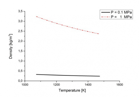
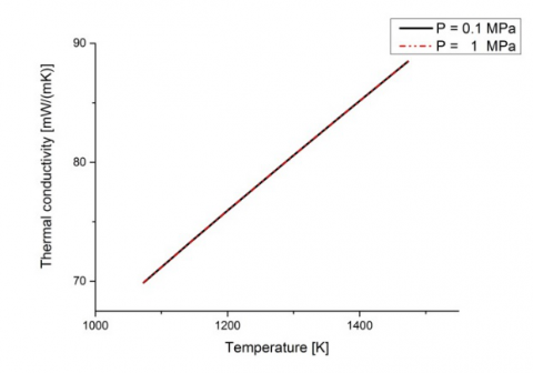
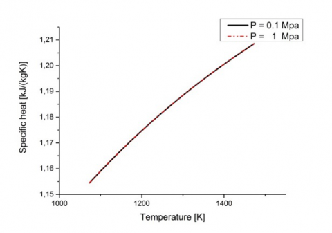
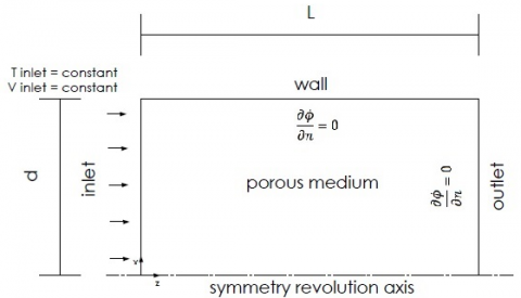
The packed bed storage system geometry considered in the investigation is a 2D axisymmetric cylindrical tank whose diameter is 0.60 m and height is 1.0 m. Packed bed configuration with sphere is considered for porous media. Rock, steel and cordierite are used as solid storage material and air as heat transfer fluid. This storage system operates at atmospheric pressure (P= 0.1 MPa). As shown in Fig.1, pressure has a strong effect on the air density, and a minor effect on the heat capacity. In addition, it has no effect on the thermal conductivity and the dynamic viscosity of dry air. As a result, according to working conditions of storage system for fluid thermophysical properties as a function of temperature were represented respectively with Eq. (1) from [7], Eq. (2) from [9] and Eq. (3) from [8] while solid thermophysical properties are assumed constant [2]. Because, it is hard to find appropriate correlation for solid material. The geometry and thermophysical properties of solid materials are given in Fig. 2 and Table 1, respectively.
a)
b)
c)
d)
Figure 1. Thermophysical properties of air as a function of temperature. a) Density, b) Thermal conductivity, c) Specific heat, d) Dynamic viscosity [10]
$\begin{align} & {{c}_{p}}=1.9327\times {{10}^{-10}}{{T}^{4}}-7.9999\times {{10}^{-7}}{{T}^{3}}+1.1407\times {{10}^{-3}}{{T}^{2}} -4.4890\times {{10}^{-1}}T+1.057\times {{10}^{3}} \\\end{align}$ (1)
$\begin{align} & \mu =2.5914\times {{10}^{-15}}{{T}^{3}}-1.4346\times {{10}^{-11}}{{T}^{2}}+5.0523\times {{10}^{-8}}T +4.1130\times {{10}^{-6}} \\\end{align}$ (2)
$k=1.5207\times {{10}^{-11}}{{T}^{4}}-4.8574\times {{10}^{-8}}{{T}^{2}}+1.0184\times {{10}^{-4}}$ (3)
Figure 2. Physical system in charging phase.
Table 1. Thermophysical properties of solid storage materials
|
|
cvs [J/m3 K] |
ρ [kg/m3] |
k [W/m K] |
|
Rock [6] |
2458 |
2560 |
0.48 |
|
Cordierite [4] |
900 |
2300 |
2.5 |
|
Steel [6] |
4454 |
7800 |
50 |
In this study first charging cycle of thermal energy storage system is examined. In the charging case air enters the system at 1473 K and the initial temperature of packed bed TES system is equal 1073 K. Heat loses with the external environment is neglected.
Numerical simulations are carried out two different mass flow rate and three porosity values and three different solid materials. Results are given in terms of stored thermal energy as a function of time. The stored thermal energy is evaluated using following equations as given in [2].
${{Q}_{stored}}={{\rho }_{eff}}{{c}_{eff}}\left[ \underset{V}{\overset{{}}{\mathop \int }}\,TdV-{{T}_{i}}V \right]$ (4)
where V=0.283m3 and Ti =1073K
${{\rho }_{eff}}=\varepsilon {{\rho }_{f}}+\left( 1-\varepsilon \right){{\rho }_{s}}$ (5)
${{c}_{eff}}=\varepsilon {{c}_{f}}+\left( 1-\varepsilon \right){{c}_{s}}$ (6)
2.2 Governing equations
Brinkman-Forchheimer-extended Darcy model is used for momentum equation and the porous medium is assumed to be in local thermal non-equilibrium with the fluid. In addition, it is assumed that the fluid is incompressible and the flow is unsteady. Heat transfer by radiation and heat losses to the surrounding are neglected. The flow is fully developed in the channel. The governing equations for mass, momentum and energy are, [1-3]:
$\frac{1}{r}\frac{\partial }{\partial r}\left( r{{v}_{p}} \right)+\frac{\partial {{u}_{p}}}{\partial z}=0$ (7)
$\begin{align} \frac{\partial \varepsilon {{\rho }_{f}}{{u}_{p}}}{\partial t}+\varepsilon {{\rho }_{f}}{{v}_{p}}\frac{\partial {{u}_{p}}}{\partial r}+\varepsilon {{\rho }_{f}}{{u}_{p}}\frac{\partial {{u}_{p}}}{\partial z}=-\frac{{{\partial }_{p}}}{\partial z} +\varepsilon \mu \left( \frac{{{\partial }^{2}}{{u}_{p}}}{\partial {{r}^{2}}}+\frac{1}{r}\frac{\partial {{u}_{p}}}{\partial r}+\frac{{{\partial }^{2}}{{u}_{p}}}{\partial {{z}^{2}}} \right)-{{\varepsilon }^{2}}\frac{\mu }{K}{{u}_{p}} -{{\varepsilon }^{3}}\frac{{{C}_{2}}{{\rho }_{f}}}{2}\sqrt{{{u}_{p}}^{2}+{{v}_{p}}^{2}{{u}_{p}}} \\\end{align}$ (8)
$\begin{align} \frac{\partial \varepsilon {{\rho }_{f}}{{v}_{p}}}{\partial t}+\varepsilon {{\rho }_{f}}{{v}_{p}}\frac{\partial {{v}_{p}}}{\partial r}+\varepsilon {{\rho }_{f}}{{u}_{p}}\frac{\partial {{v}_{p}}}{\partial z}=-\frac{{{\partial }_{p}}}{\partial z} +\varepsilon \mu \left( \frac{{{\partial }^{2}}{{v}_{p}}}{\partial {{r}^{2}}}+\frac{1}{r}\frac{\partial {{v}_{p}}}{\partial r}+\frac{{{\partial }^{2}}{{v}_{p}}}{\partial {{z}^{2}}} \right)-{{\varepsilon }^{2}}\frac{\mu }{K}{{v}_{p}} -{{\varepsilon }^{3}}\frac{{{C}_{2}}{{\rho }_{f}}}{2}\sqrt{{{u}_{p}}^{2}+{{v}_{p}}^{2}{{v}_{p}}} \\\end{align}$ (9)
$\begin{align} \varepsilon {{\left( \rho {{c}_{p}} \right)}_{f}}\frac{\partial {{T}_{f}}}{\partial t}+~\varepsilon {{\left( \rho {{c}_{p}} \right)}_{f}}\left( {{v}_{p}}\frac{\partial {{T}_{f}}}{\partial r}+{{u}_{p}}\frac{\partial {{T}_{f}}}{\partial z} \right)= \varepsilon {{k}_{f}}\left( \frac{\partial {{T}_{f}}}{\partial {{r}^{2}}}+\frac{1}{r}\frac{\partial {{T}_{f}}}{\partial r}+\frac{\partial {{T}_{f}}}{\partial {{z}^{2}}} \right)+{{h}_{sf}}{{a}_{sf}}\left( {{T}_{s}}-{{T}_{f}} \right) \\\end{align}$ (10)
$\begin{align} \left( 1-\varepsilon \right){{\left( \rho c \right)}_{s}}\frac{\partial {{T}_{s}}}{\partial t}=\left( 1-\varepsilon \right){{k}_{s}}\left( \frac{\partial {{T}_{s}}}{\partial {{r}^{2}}}+\frac{1}{r}\frac{\partial {{T}_{s}}}{\partial r}+\frac{\partial {{T}_{s}}}{\partial {{z}^{2}}} \right) -{{h}_{sf}}{{a}_{sf}}\left( {{T}_{s}}-{{T}_{f}} \right) \\\end{align}$ (11)
where C2 = 2CK-0.5
The permeability K and inertia coefficient C of porous media for packed bed configuration are based on two relations [3],
$K=\frac{{{d}_{p}}^{2}{{\varepsilon }^{3}}}{175{{\left( 1-\varepsilon \right)}^{2}}},~C=\frac{1.75}{\sqrt{150}{{\varepsilon }^{1.5}}}$ (12)
The convective heat transfer coefficient and interface area per volume of packed bed are based on two relations, [4]
${{h}_{sf}}=\frac{{{k}_{f}}\left( 2+1.1P{{r}^{1/3}}R{{e}_{p}}^{0.6} \right)}{{{d}_{p}}};~{{a}_{sf}}=\frac{6\left( 1-\varepsilon \right)}{{{d}_{p}}}$ (13)
$R{{e}_{p}}=\frac{\left| v \right|{{d}_{p}}}{v}$ (14)
Coefficients were calculated using the permeability values given in the reference [2].
The results from numerical simulations have been obtained using the commercial ANSYS fluent software. A 2D-axialsymmetric option is enabled to simulate the storage system. The geometry of high temperature sensible heat storage system is cylindrical. While the fluid thermo-physical properties are temperature dependent, the solid’s properties assumed as constant. The governing equations are solved for incompressible laminar flow and fully developed forced convection in transient regime. Because of solid and fluid phases have significantly different heat capacities and thermal conductivities, the local thermal non-equilibrium model (LTNE) is used to model heat transfer in the porous medium.
For thermal energy storage system, with packed bed configuration, mass flow inlet boundary conditions are used at inlet section. Outflow boundary conditions are used at the outlet section to obtain fully developed flow and no-slip boundary conditions are used for wall. While walls considered adiabatic, inlet section temperature is assigned 1473 K. The initial temperature of solid zone and fluid is assumed to be equal to 1073K.
The SIMPLE algorithm is used to couple pressure and velocity. The convergence criteria of 10-3 for the residual of continuity equation and velocity component and 10-6 for the residuals of the energy. A second order upwind scheme is used for spatial discretization of the convective fluxes as well as the transient one with a first-order implicit formulation. Presto is selected as pressure interpolation scheme.
A grid dependence analysis is accomplished for G = 0.4 kg/m2s, Tinlet = 1473K , ε = 0.6. Five meshes are considered: 20x60, 40x120, 80x240, 160x480, and 320x960. Volumetric fluid average temperature is monitored. Among results the mesh 160x480 is used. For time step the Courant- Friadrichs – Lewy (CFL) number provides a guide for choosing a time step in an implicit solution. This is a minimum requirement for explicit solution, but it can be restrictive because it causes too time step as the mesh size decreases. Since the implicit solution is steady for all time step, this condition can be relaxed to a converged solution instead. Also, dependence analysis was carried out for different time steps and 5 s time step was chosen.
A comparison between the presented study and reference [2] is given for different porosities and two time of computational simulation for a packed bed with steel spheres and same geometry with [2] in Table 2. As we can see from Table 2, the obtained results best match with the results of reference [2].
Table 2. A comparison about stored thermal energy values for different porosities and two time of computational simulation for a packed bed steel spheres
|
Porosity |
Qstored [kJ] 3600 s |
Qstored [kJ] 7200 s |
||
|
[2] |
Presented |
[2] |
Presented |
|
|
0.2 |
228993 |
225468 |
376386 |
357636
|
|
0.3 |
248076 |
236811
|
376379
|
363078 |
|
0.35 |
255517 |
246649
|
371042
|
366300
|
|
0.40 |
270274 |
252740
|
374796
|
369237
|
|
0.45 |
262398 |
249766
|
347110
|
345105
|
|
0.50 |
263517 |
249815
|
332258
|
331826
|
|
0.60 |
250651 |
242150
|
288679
|
289021 |
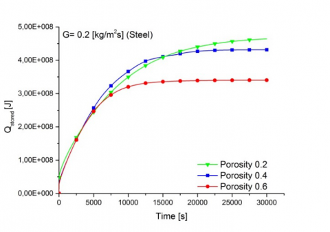
Numerical solutions are carried out for 0.2 and 0.4 constant mass flow rate with 0.2, 0.4 and 0.6 porosity values. The charging phase is considered completed when the initial temperature of the system becomes equal to inlet fluid temperature which is 1473 K. Results are presented in terms of stored energy profiles for steel, cordierite and rock spheres.
a)
b)
c)
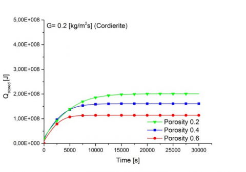
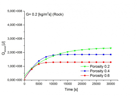
Figure 3. Stored energy in charge cycle for G=0.2 kg/m2s and different porosity values in packed bed with steel spheres a) Steel, b) Cordierite, c) Rock
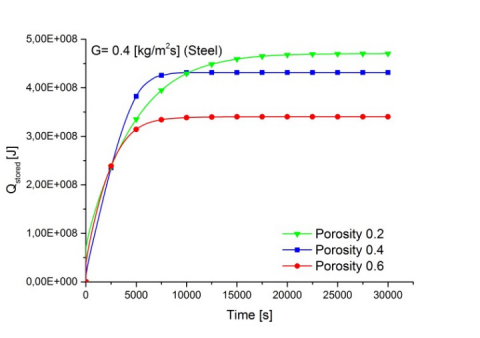
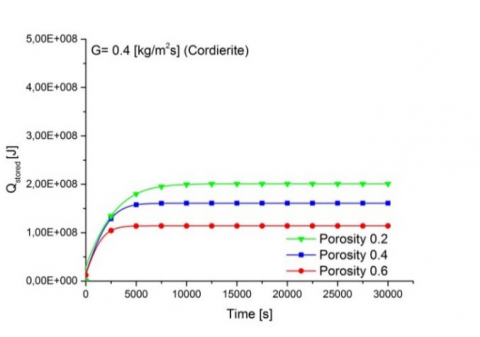
Fig. 3 and 4 shows the energy stored values as a function of time, for porosity values 0.2, 0.4 and 0.6 and mass flow rate values equal to 0.2 and 0.4 kg/m2s, respectively. At each porosity, the stored thermal energy reaches steady state conditions, which indicates the thermal saturation of the tank. Also, the trends show that the stored energy is higher for the lower porosity values because of thermal capacity increase as seen in Fig. 3 and 4. Three different materials which are steel, cordierite and rock are compared as storage material. As seen in the Table 1, they are different in respect to heat capacity, thermal conductivity and solid density. Among the materials, steel has the highest volumetric heat capacity while rock and cordierite have lower value. The most important property of the storage material is the volumetric heat capacity whereas the thermal conductivity of the solid only has a small effect on the stored energy. So, the maximum heat stored is achieved in the packed bed with steel spheres, the stored energy of cordierite and rock spheres are in close values as seen Fig.3 and 4. For assigned porosity values in Fig.3 and 4, when the mass flow rate increases the stored energy values are not change.
a)
b)
c)
Figure 4. Stored energy in charge cycle for G=0.4 kg/m2s and different porosity values in packed bed with spheres a) Steel, b) Cordierite, c) Rock
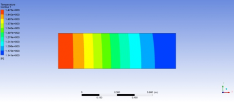
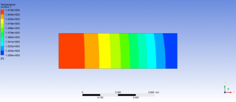
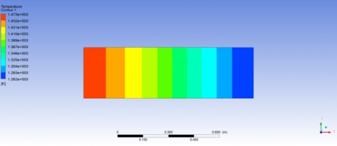
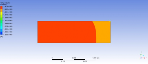
The effect of the mass flow rate is showed also in Fig. 5 according to the average solid temperature fields in 3600 s charge cycle for 0.6 porosity value and the packed bed with steel spheres. When the mass flow increases the stored energy are not change, storage time decreases due to more efficient convective heat transfer between the fluid and solid matrix for same charge cycle as seen in Fig.5. Figure 6 shows the effect of porosity values on the average solid temperature fields in 3600 s charge cycle for the packed bed with cordierite spheres and for 0.4 kg/m2s mass flow rate. When the porosity value increases the stored energy decreases in the packed bed at the same charge cycle.
a)
b)
Figure 5. Average solid temperature fields in 3600 s charge cycle for 0.6 porosity values packed bed with steel spheres a) 0.2 kg/m2s, b) 0.4 kg/m2s
The stored energy values are given for the first six hours of simulation time in Table 3 and 4. For all storage material, after 3 hours, thermal energy stored reaches almost maximum value In Table 3, increasing mass flow rate from 0.2 kg/m2s to 0.4 kg/m2s is no effect on the amount of stored energy while storage time decreases due to more efficient convective heat transfer between the fluid and solid matrix. Table 4 helpful to compare the stored energy for three studied porosity values, 0.2, 0.4 and 0.6 for 0.2 kg/m2s.
a)
b)
c)
Figure 6. Average solid temperature fields in 3600 s charge cycle for 0.4 kg/m2s mass flow rate for packed bed with cordierite spheres a) ε=0.2, b) ε=0.4, c) ε=0.6
Table 3. Stored thermal energy values for porosity 0.6 and different time of computational simulation with different solid storage materials. a) G=0.2 kg/m2s, b) G=0.4 kg/m2s
|
G=0.2 kg/m2s |
|||
|
|
Qstored [kJ] 3600 s |
Qstored [kJ] 7200 s |
Qstored [kJ] 10800 s |
|
Cordierite |
95686 |
112767 |
113907 |
|
Rock |
98986 |
126139 |
129406 |
|
Steel |
203340 |
291448 |
324681 |
|
|
Qstored [kJ] 14400 s |
Qstored [kJ] 18000 s |
Qstored [kJ] 21600 s |
|
Cordierite |
114005 |
114015 |
114016 |
|
Rock |
129649 |
129681 |
129684 |
|
Steel |
334772 |
338076 |
339436 |
a)
|
G=0.4 kg/m2s |
|||
|
|
Qstored [kJ] 3600 s |
Qstored [kJ] 7200 s |
Qstored [kJ] 10800 s |
|
Cordierite |
111560 |
113978 |
114015 |
|
Rock |
123678 |
129575 |
129681 |
|
Steel |
283064 |
333127 |
339076 |
|
|
Qdepolanan [kJ] 14400 s |
Qdepolanan [kJ] 18000 s |
Qdepolanan [kJ] 21600 s |
|
Cordierite |
114016 |
114016 |
114016 |
|
Rock |
129685 |
129685 |
129685 |
|
Steel |
340107 |
340303 |
340339 |
b)
Table 4. Stored thermal energy values for mass flow rate 0.4 kg/m2s and different time of computational simulation with different solid storage materials. a) ε=0.2, b) ε=0.6
|
ε=0.2 |
|||
|
|
Qstored [kJ] 3600 s |
Qstored [kJ] 7200 s |
Qstored [kJ] 10800 s |
|
Cordierite |
159895 |
194198 |
199981 |
|
Rock |
170160 |
219625 |
231917 |
|
Steel |
286096 |
389150 |
436787 |
|
|
Qstored [kJ] 14400 s |
Qstored [kJ] 18000 s |
Qstored [kJ] 21600 s |
|
Cordierite |
200927 |
200974 |
200976 |
|
Rock |
234318 |
234783 |
234821 |
|
Steel |
457037 |
465640 |
468725 |
a)
|
ε=0.6 |
|||
|
|
Qstored [kJ] 3600 s |
Qstored [kJ] 7200 s |
Qstored [kJ] 10800 s |
|
Cordierite |
111560 |
113978 |
114015 |
|
Rock |
123678 |
129575 |
129680 |
|
Steel |
283063 |
333127 |
339076 |
|
|
Qstored [kJ] 14400 s |
Qstored [kJ] 18000 s |
Qstored [kJ] 21600 s |
|
Cordierite |
114015 |
114015 |
114015 |
|
Rock |
129684 |
129684 |
129684 |
|
Steel |
340106 |
340303 |
340339 |
b)
A numerical investigation on packed bed thermal energy storage system (TES) in the form of sensible heat was carried out. Storage system contains solid heat storage material and fluid. The numerical model was accomplished in local thermal non equilibrium model with transient regime. Numerical simulations were carried out for a cylindrical tank in a single charge cycle. The difference is defined by the different type of storage material, mass flow rate and porosity values. Results were given in terms of stored thermal energy in porous medium as a function of time. Results showed that, for the considered parameter values, steady-state case was obtained after three hours for all considered porosity values and mass flow rates. In addition, the charging time decrease increasing the mass flow rate while the opposite is validate for porosity. Among the materials, steel was the highest energy-storing material due to high volumetric heat capacity whereas cordierite and rock has nearly same and lower energy stored value in according to steel.
|
a |
area, m-2 |
|
cp |
spesific heat, J kg-1 K-1 |
|
cvs |
volumetric heat capacity of solid, J m-3 K-1 |
|
C2 |
inertial resistance coefficient, m-1 |
|
D |
tank diameter, m |
|
G k |
mass flow per unit section, kg m-2 s-1 thermal conductivity, W m-1 K-1 |
|
L |
height of tank, m |
|
Nu |
local Nusselt number |
|
g |
gravity, m s-2 |
|
Pr |
Prandtl number |
|
Re |
Reynolds number |
|
Q |
thermal energy, J |
|
Qstored |
stored thermal energy, J |
|
t |
time, s |
|
T |
temperature, K |
|
V |
volume, m3 |
|
Greek symbols |
|
|
ε |
porosity |
|
$\rho$ |
density, kg m-3 |
|
µ |
dynamic viscosity, kg m-1s-1 |
|
Subscripts |
|
|
eff |
effective |
|
f |
fluid |
|
in |
inlet |
|
s |
solid |
[1] Anderson R., Bates L., Johnson E., Morris J.F. (2012). Packed bed thermal energy storage: A simplified experimentally validated model, Journal of Energy Storage, No. 4, pp. 14-23. DOI: 10.1016/j.est.2015.08.007
[2] Andreozzi A., Buonomo B., Manca O., Mesolella P., Tamburrino S. (2009). Numerical investigation of sensible thermal energy storage in high temperature solar systems, Computational Methods and Experimental Measurements XIV, WIT Transactions on Modelling and Simulation, Vol. 48. DOI: 10.2495/CMEM090421
[3] Andreozzi A., Buonomo B., Manca O., Mesolella P., Tamburrino S. (2012). Numerical investigation on sensible thermal energy storage with porous media for high temperature solar systems, 6th European Thermal Sciences Conference (Eurotherm 2012), Journal of Physics: Conference Series, p. 395. DOI: 10.1088/1742-6596/395/1/012150
[4] Andreozzi A., Buonomo B., Manca O., Nardini S., Tamburrino S. (2013). Heat transfer behaviors of thermal energy storages for high temperature solar systems, Industrial and Technological Applications of Transport in Porous Materials, Delgado J.M.P.Q. (ed.), Springer- Verlago, Heidelberg. DOI: 10.1007/978-3-642-37469-2_5
[5] Zanganeh G., Pedretti A., Zavattoni S., Barbato M., Steinfeld A. (2012). Packed-bed thermal storage for concentrated solar power – Pilot-scale demonstration and industrial-scale design, Solar Energy, No. 86, pp. 3084-3098. DOI: 10.1016/j.solener.2012.07.019
[6] Hänchen M., Brückner S., Steinfeld A. (2011). High-temperature thermal storage using a packed bed of rocks -heat transfer analysis and experimental validation, Applied Thermal Engineering, No. 31, pp. 1798-1806. DOI: 10.1016/j.applthermaleng.2010.10.034
[7] ITU Ninova, Spesific Heat of Air vs. Temperature plot, from http://ninova.itu.edu.tr/tr/dersler/ucak-uzay-fakultesi/965/uck-421, accessed on 10 March 2017.
[8] Livre L., Thermal Conductivity of Air vs. Temperature Plot, from http://bouteloup.pierre.free.fr/lica/phythe/don/air/air_k_plot.pdf, accessed on 10 March 2017.
[9] Zografos A.I., Martin W.A., Sunderland J.E. (1987). Equations of properties as a function of temperature for seven fluids, Computer Methods in Applied Mechanics and Engineering, Vol. 61, No. 2, pp. 177-187. DOI: 10.1016/0045-7825(87)90003-X
[10] Agalit H., Zari N., Maalmi M., Maaroufi M. (2015). Numerical investigations of high temperature packed bed TES systems used in hybrid solar tower power plants, Solar Energy, No. 122, pp. 603-616. DOI: 10.1016/j.solener.2015.09.032