OPEN ACCESS
Medium temperature solar thermal applications have received remarkable interest in the recent years in both residential and industrial sectors. These applications, typically in a temperature range of 80 - 250°C, require thermal collectors coupled to solar concentrators. Concerning these applications, a prototype of Compound Parabolic Concentrator coupled to an Evacuated Tube solar collector, was developed and built. The instantaneous efficiency of the prototype was measured according to the suggestions of the European Standard EN 12975-2. The "Outdoor steady-state" test method, well accepted for testing flat plate and evacuated tubular collectors, was used. The specific useful power extracted from the prototype was also derived. The measured performance is in line with theoretical derivations. However, when using the instantaneous efficiency of the Outdoor steady state test method some discrepancies arise in simulating the daily behavior of the collector, suggesting a different testing approach.
solar thermal collector, non-imaging optics, CPC
Solar concentrating collectors are devices used to collect solar energy for applications with a temperature range of 80–250°C. These medium temperature solar thermal applications have received remarkable interest in the recent years in both residential and industrial sectors. A large review of the different types of solar concentrating collectors and of their most successful solar thermal applications can be found in [1].
Among the different types of concentrators, Compound Parabolic Concentrators (CPC in the following) have attracted a large attention. CPCs are non-imaging concentrators with the capability of intercepting and reflecting the incident solar radiation to the absorbing surface over a wide-angle range. With a proper choice of orientation and inclination it is possible to avoid expansive tracking systems. An additional reason of the interest is the capability of accepting diffuse solar radiation. A large review of the solar thermal applications of CPCs can be found in [2].
The behaviour of a CPC is governed on the rules of the Non-imaging optics. Non-imaging optics is applied in different field of the engineering technology, from complex reflectors in the automotive industry to many solar related applications. Their first use is reported to be with Cernkov detectors in particle physics investigations [3].
In the present paper we discuss a prototype of solar thermal collector with a macrofocal non imaging reflector. This reflector was designed for having an accepting half angle of 31° and its shape was conceived for coping with a cylindrical absorber at a given gap from mirror bottom end. Inside the absorber a U-shaped pipe used as the water heat transfer device, is placed.
The thermal performance of this prototype is derived in a series of experiments. For the experimental investigation, a testing facility is used, designed for the evaluation of the instantaneous thermal efficiency and taking the standard EN 12975-2 [4] as the reference. In the present paper the results, expressed in terms of efficiency and thermal production, obtained with the Outdoor Steady State (OSS) approach are presented and discussed.
The reflector of a CPC belongs to a family of convex surfaces made by several basic profiles able to concentrate the incoming rays onto a receiver without recreating the original “image” of the ray original source. The shape of the reflector depends on the shape of the receiving surface to be impinged, as first discussed in details for a series of target profiles in [5, 6].
Of particular interest in solar applications are the tubular receivers, made by a single cylinder or by a coaxial pair of tubes with the absorbing surface located in the inner one.
In this case the mirror shape has been described by Mc Intire [7] based on the geometrical parameters described in Figure 1. Being R the receiver radius, f the parametric angle from vertical (mirror) axis y, the tangential distance from receiver to mirror envelop r(f) is given by the following formulas, describing either an involute of a circle of radius R or a macrofocal parabola:
Figure 1. Geometry of a CPR for a tubular receiver
$\rho(\phi)=\left\{\begin{array}{l}{\frac{R\left[\pi / 2+\phi+\theta_{a c c}-\cos \left(\phi-\theta_{a c c}\right)\right]}{1+\sin \left(\phi-\theta_{a c c}\right)}} \\ {R \phi, \quad|\phi| \leq \theta_{a c c}+\pi / 2}\end{array}\right.$ (1)
The (full) height of the CPC is related to its concentration ratio C (which in turn depends on the half acceptance angle qacc) and receiver radius R according to the relationship:
$h_{f u l l}=R \pi\left(\frac{1}{C \operatorname{tg}\left(\theta_{a c c}\right)}+0.5+\frac{1}{C \pi}\right)$ (2)
where the concentration ratio can be expressed either in terms of the acceptance angle or with reference to the aperture A and receiver radius R:
$C=\left\{\begin{array}{l}{A / 2 \pi R} \\ {1 / \sin \left(\theta_{a c c}\right)}\end{array}\right.$ (3)
Since the upper part of the mirror does not significantly contribute to the reflector aperture, often the reflector height is reduced (or “truncated”) to a lower value h < hfull. In this case the concentration ratio is reduced too and this penalty factor can be estimated according to the plane receiver theory or to the circular one [5, 7]. A correction factor has been here calculated according to the above investigations and the results are reported in Figure 2 for accepting angles in the range 25 to 35°.
Figure 2. Effect of the height truncation on the concentration ratio in the acceptance angle range 25-35°
Based on the above relationships and the corrections suggested by Winston et al. [8] for displaced tubular receiver with respect to involute cusp, a concentrator profile has been calculated taken into account a series of constraints, starting from the receiver geometry. The choice of the receiver has been addressed to commercial evacuated tubes having the absorbing coating onto the outer surface of the inner glass tube at a radius R = 18.5 mm. Due to the presence of outer tube and evacuated annular space, a 5-mm displacement (gap) with respect of the mirror cusp (f = 0) resulted.
The other constraint of the present design was the aperture angle. Since the goal of the overall project was to develop a solar collector with some concentration but without the need of tracking the sun, the choice was to select an angle large enough to account for the declination angle effects on the sun altitude in the sky and able to collect a meaningful amount of diffuse solar energy. Being the declination angle effect of +/-23.45° an acceptance angle of 31° was chosen as a tradeoff value for high concentration ratio and broad view of the sky dome where the sun is moving. The h/hfull ratio was chosen equal to 0.5: inspection of Figure 2 (q = 30°) reveals that the concentration ratio is reduced by a 0.87 factor with respect to its maximum value of 2.0.
The resulting mirror profile is depicted for the above geometrical parameters in Figure 3 where the absorber cylindrical surface is displaced with respect to the mirror cusp for the reasons discussed in the previous section.
Figure 3 CPR prototype: calculated profile for a tubular receiver with R = 18.5 mm and vertical displacement with respect to involute cusp equal to 5 mm
A detailed description of the test equipment is given in [9]. Consequently, here just a short description of its main characteristics is given. In particular, since the original set-up was designed for non-concentrating solar collectors, a detailed description of modifications and of the new test section is here reported.
The CPC was placed horizontally, with the receiver in the direction E-W. Based on the south orientation of the measuring system and the latitude of Ferrara (44.84° N), the city where it is located, the requirement over the transverse angle made necessary a tilt of the plane of the CPC solar collector of 30° with respect to the horizontal plane. In this way, the CPC solar collector was able to capture the sun radiation for a wide part of the year, except for a couple of months in the winter.
Transversally on this new plane two further supporting rods were placed, specifically dimensioned for bearing the CPC solar collector, which has, as the receiver, a single evacuated tube. This tube consists of an outer thin glass pipe and an inner glass absorber with a selective coating. A U-shaped pipe (8 mm OD, 6 mm ID), in thermal contact by means of a fin with the absorber, is used as the heat transfer device. Liquid water is used as the heat transfer fluid.
As discussed in [9], the testing system follows as far as possible EN 12975-2 [4]. The hydraulic circuit described in [9] was not changed both in the fluid preparing section (pump, heat exchanger, expansion vessel, flow regulation valve and flowmeter), and in the measuring instruments for global and beam solar irradiance and ambient air temperature.
The pressure and temperature probes are in the inlet and outlet sections of the U-shaped pipe placed inside the receiver. The probes are at the same extremity of the CPC. Some clamps for the connection of the pipes to the rods were necessary to support this part of hydraulic circuit. Since the U-tube of copper placed inside the receiver is long and thin (8 mm OD, 6 mm ID) and thence weak, it was necessary to create a rigid supporting system where to place the pressure and temperature probes that, on the contrary, are heavy and short.
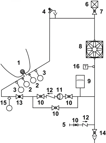
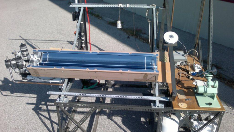
Figure 4 shows a scheme of the testing equipment used for this CPC solar collector. In Figure 5 a photo of the testing system with the CPC is shown.
Figure 4. Scheme of the closed loop test equipment: 1 Solar Collector, 2 Pressure Transducer, 3 RTD sensor, 4 Safety Valve, 5 Water Supply, 6 Air Vent, 7 Shut-off Valve, 8 Air Heater, 9 Expansion Tank, 10 By-pass Valve, 11 Pump, 12 Check Valve, 13 Balancing Valve, 14 Emptying Valve, 15 Flow Meter, 16 Immersion Thermostat
Figure 5. The test equipment with the prototype of CPC. (the CPC is still protected by a light blue polymeric film
The data are acquired with an Agilent 34970A multimeter, driven via a PC by means of a Labview software.
The overall uncertainty, estimated at the 95% confidence level, is calculated with the root-sum-square propagation rule by following the procedure proposed by Moffat [10] (see [9] for a deeper discussion).
The tests were executed by following as far as possible, the performance test method called "Outdoor steady-state" (OSS) in EN 12975-2 [4]. The performance of the CPC solar collector is evaluated on its instantaneous efficiency, calculated by statistical curve fitting on the base of a curve of the form:
$\eta=\eta_{0}-a_{1} T^{*}-a_{2} G\left(T^{*}\right)^{2}$ (4)
or, if the quadratic term is not statistically significant, as:
$\eta=\eta_{0}-a_{1} T^{*}$ (5)
where the experimental data of instantaneous efficiency are calculated as:
$\eta=\frac{Q}{G A}=\frac{m c_{f}\left(T_{o u t}-T_{i n}\right)}{G A}$ (6)
the reduced temperature T* is given by:
$T^{*}=\frac{T_{m}-T_{a}}{G}$ (7)
and the mean temperature Tm is given by:
$T_{m}=\frac{T_{i n}+T_{o u t}}{2}$ (8)
As discussed in [9], in this experimental setup the inlet temperature is always near the ambient temperature; for this reason, the test conditions and in particular the reduced temperature, Eq. (7), can be changed with an appropriate mass flow rate. Minimum and maximum flow rates define the minimum and maximum reduced temperatures, T*. The data were gathered in September, inside the time window of the acceptance angle.
The experimental data and other calculated values useful for the data reduction are shown in Tables 1 and 2. Each test reported in these Tables resumes the mean of a group of data.
The measurements were carried out 15 min after the attainment of a steady volumetric flow rate. During each data acquisition, a time scanning of 20 s is requested. This operation is repeated 10 times for each experimental point.
In the calculations of efficiency, h, and specific useful power extracted, Q/A, the reference surface is the aperture area of the collector (0.21 x 1.45 m2).
In Figure 6 the instantaneous efficiency, h, is shown as a function of the reduced temperature difference, T*. The experimental data are available for values of T* in the range 0.004 ≤ T* ≤ 0.032 m2KW-1. Due to the very low values of the wind velocity (Table 1) this is a case where the quadratic term of a parabolic fit (EN 12975-2 [4]) is not statistically relevant. The efficiency of the CPC solar thermal collector is:
Figure 6. Efficiency versus reduced temperature difference for the prototype of CPC solar collector
$\eta=0.5882-2.571 T^{*}$ (9)
The data shown in Table 1 mainly are in accordance with the requirements of the standard EN 12975-2 [4]. Some deviations can be recognized: the diffuse radiation in Tests Nr. 3, 6 and 9 exceed the limit of 30% of the total irradiance; the hemispherical solar irradiance of test Nr. 3 is lower than 700 W/m2. Nevertheless, the coherence of the data distribution guaranties that the interpolation is unaffected by this limit.
In Figure 6 both the dependent and independent variables are affected by an experimental uncertainty. The highest uncertainties are encountered for the lowest and the highest values of T*, for T* and h, respectively.
The absolute uncertainty of h increases with T*. This is due to the flow rate measurement; in the prototype with a single evacuated tube and a low useful power extracted, in order to obtain the highest values of T*, very low flow rates are needed, near the limiting capabilities of the flowmeter. In Eq. (6) a high uncertainty in m is the reason of a high uncertainty in h.
The absolute uncertainty of T* is quite constant and necessarily its relative uncertainty becomes high for the lowest values of T*.
Since both efficiency and reduced temperature difference are affected by an experimental uncertainty, the interpolation is performed by considering the uncertainties both in the dependent and independent variables [11].
By following the standard EN 12975-2 [4], the specific collector output, Q/A, is a function of the difference of
temperature between heat transfer fluid and ambient, Tm -Ta:
$\frac{Q}{A}=0.5882 G-2.571\left(T_{m}-T_{a}\right)$ (10)
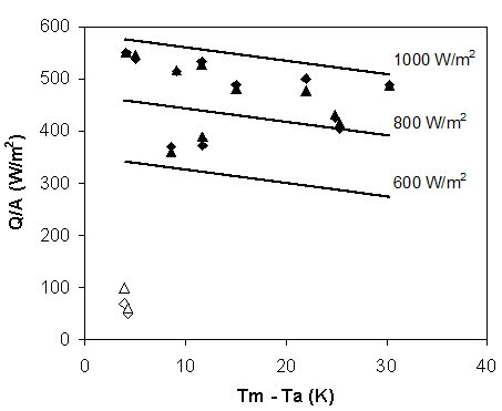
In Figure 7 the performances of the CPC solar collector are shown in terms of specific useful power extracted, Q/A, as a function of the temperature difference between mean fluid and ambient temperature, Tm - Ta. The experimental values (Table 1, diamonds) are compared with their theoretical counterparts (Eq. 10, triangles). As can be observed the agreement is very good.
Figure 7. Experimental collector output per unit of aperture area (triangles) compared with the estimations of Eq. (10) (diamonds). Empty symbols refer to overcast sky performance (diffuse radiation is dominant)
In Figure 7 is also shown the specific collector output, Q/A, given by Eq. (10), for values of global irradiance G = 600, 800 and 1000 W/m2. The typical behaviour of an evacuated tube solar collector can be recognized, characterized, for a fixed value of the global solar irradiance, by a slow decrease of production for increasing values of Tm - Ta, due to the high level of thermal insulation given by the evacuated tube.
Table 1. Experimental data
|
Test |
G |
Gd |
m |
Tin |
Tout |
Ta |
u |
|
Nr. |
W/m2 |
W/m2 |
kg/h |
°C |
°C |
°C |
m/s |
|
1 |
959.4 |
186.5 |
20.5 |
27.1 |
34.2 |
26.6 |
1.3 |
|
2 |
955.8 |
180.4 |
15.5 |
27.1 |
36.3 |
26.7 |
1.3 |
|
3 |
653.1 |
329.9 |
10.5 |
32.0 |
41.4 |
28.2 |
1.3 |
|
4 |
922.6 |
171.4 |
9.3 |
27.5 |
42.3 |
25.8 |
1.3 |
|
5 |
952.2 |
200.3 |
8.0 |
30.7 |
48.5 |
28.0 |
1.3 |
|
6 |
715.6 |
340.9 |
6. 6 |
32.5 |
47.6 |
28.4 |
1.3 |
|
7 |
911.0 |
181.7 |
6.7 |
36.1 |
56.5 |
24.35 |
1.0 |
|
8 |
888.5 |
158.2 |
5.0 |
27.0 |
53.1 |
25.0 |
1.3 |
|
9 |
845.8 |
223.3 |
4.3 |
34.9 |
61.5 |
23.3 |
1.0 |
|
10 |
966.6 |
162.3 |
2.6 |
28.6 |
78.8 |
23.4 |
1.0 |
|
11 |
822.1 |
335.8 |
2.7 |
33.1 |
73.2 |
27.8 |
1.3 |
Table 2. Calculated values based on experimental data
|
Test |
Gd/G |
Re |
m/A |
Q/A |
T* |
h |
||
|
Nr. |
|
|
kg/(hm2) |
W/m2 |
m2K/W |
|
||
|
1 |
0.194 |
1544 |
66.5 |
550.3 |
0.0043 |
0.574 |
||
|
2 |
0.189 |
1195 |
50.3 |
538.3 |
0.0053 |
0.563 |
||
|
3 |
0.505 |
898 |
34.2 |
370.0 |
0.0131 |
0.566 |
||
|
4 |
0.186 |
760 |
30.0 |
514.4 |
0.0099 |
0.557 |
||
|
5 |
0.210 |
716 |
25.8 |
533.0 |
0.0122 |
0.560 |
||
|
6 |
0.476 |
596 |
21.3 |
372.6 |
0.0164 |
0.521 |
||
|
7 |
0.199 |
680 |
21.7 |
500.5 |
0.0241 |
0.549 |
||
|
8 |
0.178 |
451 |
16.1 |
488.7 |
0.0169 |
0.550 |
||
|
9 |
0.264 |
447 |
13.8 |
426.3 |
0.0294 |
0.504 |
||
|
10 |
0.168 |
295 |
8.4 |
489.2 |
0.0313 |
0.506 |
||
|
11 |
0.409 |
303 |
8.7 |
404.9 |
0.0308 |
0.493 |
||
In Figure 7 two further experimental data characterized by very high values of diffuse radiation (Gd/G equal to 0.992 and 0.988) are compared with the predictions of Eq. (10). Also in this limiting case (empty symbols in Figure 7) the agreement is very good.
To assure the reliability of the efficiency curves based on the OSS method of EN 12975-2 [4], in Figure 8 the thermal production predicted with Eq. (10) is compared to the experimental data gathered for the same conditions in a day of March. During this day, the global solar irradiance was that characteristic of a clear sky sunny day of spring, with limited scattered clouds in the afternoon. A peak of 1100 W/m2 characterized the total irradiance. The diffuse component of the solar irradiance was about 30% of the global irradiance before noon and 40% in the afternoon.
Figure 8. Comparison between experimental and predicted data of thermal production during a full day transient test (D: experimental data for Q/A; w: predicted data for Q/A; é: Gd/G)
Even if the conditions for the utilization of an efficiency model typical of an OSS method, Eq. (10), are satisfied, the experimental data are always lower than the predicted ones. This behavior is in line with the literature evidence [12, 13] showing that for collectors with a significant concentration ratio, the OSS method is not particularly predictive.
For concentrating solar collectors, a specific trend of the incidence angle modifier and a strong impact of the concentration factor on the performance under diffuse irradiance, are recognized as the main sources of disagreement in using steady state results. Also, the thermal capacity becomes relevant in the evaluation of data gathered over long times. For these solar collectors, a “quasi-dynamic” testing methodology, performed outdoors in natural conditions with variable radiation and ambient temperature, has been introduced.
The results of an experimental investigation are presented for a prototype of CPC solar thermal collector. The compound reflector was designed and built based on the theory of the tubular receivers displaced with respect to the reflector bottom end. The thermal characterization of the present collector follows, as far as possible, the methodology called Outdoor Steady-State, as proposed by EN 12975-2 for the determination of the instantaneous collector efficiency.
The efficiency of the present collector has been calculated based on "quasi-steady" measurements. The overall experimental data and their reduction allowed the simulations of the thermal yield of the present collector under quasi steady and transient operating modes.
Even if the agreement between measurements and predictions was always reasonably good, some aspects of the behavior of the thermal collector and of the collection of the diffuse energy seem to deserve further investigations.
The Tema srl company (Genoa, Italy) is acknowledged for its support to the present research. The authors also thanks Dr. Claudio De Domenico for his valuable cooperation during the experiments.
|
A |
CPC aperture surface (m2) |
|
C |
concentration ratio |
|
cf |
specific heat capacity of heat transfer fluid (kJ/(kgK)) |
|
G |
global solar irradiance (Wm-2) |
|
Gb |
direct solar irradiance (Wm-2) |
|
Gd |
diffuse solar irradiance (Wm-2) |
|
h |
height of the CPC (m) |
|
m |
mass flow rate of heat transfer fluid (kg/s) |
|
Q |
useful power extracted from collector (W) |
|
R |
receiver radius (m) |
|
Re |
Reynolds number |
|
T |
temperature (K) |
|
T* |
reduced temperature difference, Eq. (7) |
|
u |
surrounding air speed (ms-1) |
|
Greek symbols |
|
|
b |
tilt angle of a plane with respect to horizontal (°) |
|
e |
experimental uncertainty |
|
q |
angle (°) |
|
f |
parametric angle from vertical (mirror) axis y |
|
h |
collector efficiency, Eq. (6) |
|
r |
tangential distance from receiver to mirror envelop |
|
Subscripts |
|
|
0 |
zero-loss |
|
a |
ambient |
|
acc |
half acceptance |
|
full |
full |
|
in |
inlet |
|
m |
mean |
|
out |
outlet |
|
s |
stagnation |
|
t |
transversal |
[1] Jradi M., Riffat S. (2014). Medium temperature concentrators for solar thermal applications, International Journal of Low-Carbon Technologies, Vol. 9, pp. 214–224. DOI: 10.1093/ijlct/cts068
[2] Xu D.H., Qu M. (2013). Compound parabolic concentrators in solar thermal applications: a review, ASME 2013 7th International Conference on Energy Sustainability, Minneapolis, Minnesota, USA. DOI: 10.1115/ES2013-18409
[3] Hinterberger H., Winston R. (1966). Efficient light coupler for threshold Cernkov counters, Rev. Sci. Instrum, Vol. 37, No. 8, pp. 1094–1095. DOI: 10.1063/1.1720428
[4] EN 12975-2. (2006). Thermal solar systems and components - Solar collectors - Part 2: Test methods.
[5] Rabl A., Goodman N.B., Winston R. (1979). Practical design considerations for CPC Solar Collectors, Solar Energy, Vol. 22, pp. 373–381. DOI: 10.1016/0038-092X(79) 90192-0
[6] Gallagher J.O. (2008). Non-Imaging Optics in Solar Energy, Morgan and Claypool.
[7] W.R. Mc Intire. (1979). Truncation of non-imaging cusp concentrators, Solar Energy, Vol. 23, pp. 351-355. DOI: 10.1016/0038-092X(79)90130-0
[8] Winston R., Miñano J.C. Benítez P. (2005). Non-Imaging Optics, Academic Press.
[9] Casano G., Piva S. (2013). On the Measurement of the instantaneous efficiency of solar thermal collectors with a modified EN 12975 test facility, Int J Heat & Tech., Vol. 31, No. 4, pp. 25-30.
[10] Moffat R.J. (1994). Establishing the credibility of experimental work, Experimental Thermal and Fluid Science., Vol. 8, No. 2.
[11] Demings W.E. (1943). Statistical Adjustment of Data, New York, Wiley.
[12] Fischer S., Lüpfert E., Müller-Steinhagen H. (2006). Efficiency testing of parabolic trough collectors using the quasi-dynamic test procedure according to the European Standard EN 12975, Solar Paces 13th Symposium on Concentrating Solar Power and Chemical Energy Technologies, Sevilla.
[13] Osório T., Carvalho M.J. (2012). Testing of solar thermal collectors under transient conditions, Energy Procedia, Vol. 30, pp. 1344-1353. DOI: 10.1016/j.egypro.2012. 11.148