OPEN ACCESS
The purpose of this study was to investigate the ablation of fused silica under the irradiation of Laguerre Gauss beam. The simulation approach was adopted. The results obtained in this study include... temperature distribution and the ablation boundary morphology on fused silica irradiated under TEM00 TEM01 TEM10 Laguerre Gauss beams. it was found that the accumulation effect of temperature is obvious. The temperature rises after laser pulses irradiating and the focal area exceeds the vaporization temperature, vaporization occurs, and the ablation boundary is formed, and the ablation boundary expands and deepens with the laser pulse. The principal conclusion was that the spatial distribution of laser intensity affects the temperature distribution and the ablation boundary morphology of the material. The findings of this study may serve as the beneficial reference for the process of fused silica
laser technique, simulation, fused silica, Laguerre gauss beam, vaporization
Featuring high hardness, low expansion coefficient, high temperature resistance, and good chemical stability, and ultraviolet light and infrared light penetrability, the fused silica is widely applied in the laser devices and optical instruments thanks to its sound thermal, optical and mechanical performance. The temperature rise, fusion and vaporization of the fused silica in the irradiation of the laser caused damage to the material. In this process, the temperature and deformation of the material are not easy to be measured, but they can be effectively studied through modeling and simulation.
There are many research results at home and abroad on the theoretical calculation and simulation of the interaction between laser and material [1-4]. Yu Jingxia carried out dynamic simulation of the process of laser irradiating quartz, based on which he analyzed the changes of temperature and stress field [5]. Literature [6] compared the temperature field of the fused silica irradiated by CO2 laser and that of the BK7 glass irradiated by CO2 laser [6]. Li Shixiong et al. conducted numerical calculation on the temperature and thermal stress of the fused silica under the single pulse action [7]. Li Yi et al. studied the effect of high repetition frequency pulse on temperature accumulation effect [8]. Li Xingliang et al. carried out finite element simulation on the thermal effect of the CCD detector irradiated by laser [9] and Jiao Junke studied the temperature distribution of the quartz glass under the action of CO2 laser [10]. The morphology of the ablation boundary of fused silica has not been further studied.
Based on COMSOL platform, this paper considers the factors affecting the variation of the thermal parameters of the fused silica with the temperature and simulates the fused silica irradiated under TEM00, TEM01 and TEM10 Laguerre Gauss beams. Considering the thermal accumulation effect of the laser energy in the fused silica, the simulation adopts several continuous laser pulses to irradiate the fused quartz, and the temperature distribution and morphology of the ablation boundary are obtained. The simulation results provide a reference for the process control and laser mode selection in the process of laser machining of the fused silica.
The main contents include the basic principle, the simulation model and the parameters of laser and fused silica, as well as the analysis and discussion of the simulation results.
When the laser pulse irradiates the fused silica, considering the short acting time of the laser pulse, the conduction and convection factors of the quartz radiation and the surrounding air are ignored. The Fourier thermal conductivity equation is established as follows [11]:
$\rho C \frac{\partial T}{\partial t}+\nabla \cdot(-k \nabla T)=Q$ (1)
where, $\nabla \cdot(-k \nabla T)$ is the heat conduction item, Q is the heat source, t is time, $\rho$ is density, C is heat capacity, k is the coefficient of heat conduction and T is temperature.
When the surface temperature of the fused silica reaches the temperature of vaporization, the fused silica changes to a gas state. Considering that the vaporization process absorbs a considerable amount of energy, the surface temperature of the material will not be greatly different from the vaporization temperature. The boundary conditions for this model is:
$-\mathbf{n} \cdot(-k \nabla T)=q_{a}$ (2)
$q_{a}=h_{a}\left(T_{a}-T\right)$ (3)
where, n is the unit vector; qa refers to the heat flux absorbed during the material ablation; Ta is the vaporization temperature and ha(T) means that the heat transfer coefficient is related to temperature.
The vaporized fused silica is removed from the surface of the material. The erosion ratio of the fused silica boundary is:
$v_{a}=q_{a} /\left(\rho \cdot H_{s}\right)$ (4)
where, va is the evaporation and ablation rate of the fused silica, r is the material density of the fused silica and Hs stands for the latent heat of evaporation.
3.1 Quartz material selection and environment condition
Since the fused silica is non-crystal, its physical properties are isotropic. As the temperature of the fused silica changes, its physical parameters will change as well. Table 1 presents the parameters of the fused silica at different temperature [5].
Table 1. Physical parameters of fused silica
|
Temperature (°C) |
Thermal conductivity (W/(m×K)) |
Heat capacity (J/(kg×K)) |
Density (kg/m2) |
|
20 |
1.30 |
740 |
2200 |
|
250 |
1.56 |
987 |
2200 |
|
500 |
1.84 |
1121 |
2200 |
|
750 |
2.13 |
1178 |
2200 |
|
1000 |
2.40 |
1121 |
2200 |
|
1500 |
2.26 |
1246 |
2200 |
|
1700 |
2.28 |
1273 |
2200 |
|
2000 |
\ |
\ |
2200 |
|
2500 |
2.38 |
1273 |
2200 |
The piecewise linear function is adopted to fit the abovementioned physical parameters. The parameters below the temperature of 20°C is replaced by the parameter at the temperature of 20°C and the parameter above the temperature of 2500°C is replaced by the parameter at 2500°C for the sake of simulating calculation.
The quartz material parameters that do not vary with temperature include the absorption coefficient b=10cm-1, density r=2.2g/cm3, reflectance R=0.035 and latent heat of evaporation Hs=3.6eV [12] (i.e. 1600kJ/kg).
ha(T) means that the heat transfer coefficient is related to temperature. In order to simplify the calculated quantity, it is expressed as a ramp function ha(T)=k×T, k refers to the slope. In the simulating calculation, let k=107 and vaporization temperature Ta=2800°C.
3.2 Heat source distribution function in laser heating
Considering the nanosecond laser has long-pulsed width, when the laser passes the fused silica medium with certain thickness, since the medium absorbs partial light energy, the intensity of the transmitted light will weaken. The assimilation of the laser by the fused silica follows the Beer-Lambert Law. The energy absorbed by the fused silica is taken as the laser heating source, which is expressed as [13]:
$Q(x, y, z, t)=(1-R) \beta P(t) I(x, y, z) \exp (-\beta z)$ (5)
where, b is the material absorption coefficient, R is the material reflection coefficient, P(t) is the laser power time distribution and I(x, y, z) is the laser spatial intensity distribution.
The form of the power of Gauss laser pulse is:
$P(t)=P_{\max } \exp \left[(-4 \ln 2)\left(\frac{t}{t_{p}}\right)^{2}\right]=\left(\frac{E_{p}}{1.064 t_{p}}\right) \exp \left[(-4 \ln 2)\left(\frac{t}{t_{p}}\right)^{2}\right]$ (6)
where, Pmax is the peak pulse power, Ep is the single pulse energy, tp is the pulse width (FWHM--Full Wave at Half Maximum, full width at half-maximum).
The generalized intensity distribution of Laguerre Gaussian beam light in the cylindrical coordinate system is as follows [14]:
$I(r, \varphi, z)=\frac{2}{\pi w^{2}(z)}\left(\sqrt{2} \frac{r}{w(z)}\right)^{2 t} \cdot L_{p}^{\prime}\left(\frac{2 r^{2}}{w^{2}(z)}\right)^{2} \cdot \exp \left(\frac{-2 r^{2}}{w^{2}(z)}\right) \cdot\left\{\begin{array}{l}{\cos ^{2}(l \varphi)} \\ {\sin ^{2}(l \varphi)}\end{array}\right.$ (7)
where w(z) is the beam radius. $w(z)=w_{0}\left(1+\frac{z^{2}}{z_{R}^{2}}\right)^{0.5}$, $z_{R}=\frac{n \pi w_{0}^{2}}{\lambda}$ is the Rayleigh length. n is the medium index of refraction. $\lambda$ is the optical maser wavelength. w0 is the focal spot radius. $L_{p}^{l}$ is the Laguerre polynomial and its different order is expressed as follows:
$L_{n}^{m}(\eta)=\sum_{k=0}^{m} \frac{(n+m) !(-\eta)^{k}}{(m+k) ! k !(n-k) !}$ (8)
l and p represent angular modulus and radial modulus respectively.
$\left\{\begin{array}{l}{\cos ^{2}(l \varphi)} \\ {\sin ^{2}(l \varphi)}\end{array}\right.$ means that either $\cos ^{2}(l \varphi)$ or $\sin ^{2}(l \varphi)$ can be selected. j refers to the angle of the cylindrical coordinate system.
3.3 Model device
The laser can be used to micro-process the fused silica material, which has been studied theoretically and experimentally [15-19]. Aiming at this application of laser, a laser irradiation system model is constructed and simulating calculation is performed in this paper. As shown in Figure 1 (a), the beam irradiates on the surface of the cylinder fused silica and focuses on the central position.
The parameters of the Q Nd: YAG laser are referred: laser wavelength $\lambda$=1064nm, pulse energy Ep=1.7mJ, pulse width (full width at half-maximum, FWHM) tp=140ns. When the beam passes through the focusing lens, the radius of the focal spot w0=20$\mu \mathrm{m}$. The geometrical shape of the fused silica sample is cylinder. In order to reduce the calculation quantity of the finite element grid, the diameter of the cylindrical geometrical model is set as 80$\mu \mathrm{m}$ and the length is set as 500$\mu \mathrm{m}$ in the premise of not affecting the simulation results. The simulation process is the irradiation process of continuous laser pulses to the fused silica at 6 periods.
The temperature distribution and the morphology of the evaporation and ablation boundary were obtained by simulation using the solid heat transfer module and deformation geometry module of the COMSOL software. The outer surface of the fused quartz is adiabatic. The initial temperature and outer circumstance temperature of the fused silica is both $20^{\circ} \mathrm{C}$. The initial value of the displacement field and the velocity field is both 0; the fused silica is simulated using its physical parameter of temperature vibration. The grid dissection adopts the freely dissected tetrahedral structure. The COMSOL software’s transient adaptive mesh refinement function is used to strike a balance between the fineness of the simulation results and the computational data volume.
4.1 Distribution of temperature of the fused silica
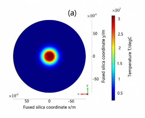
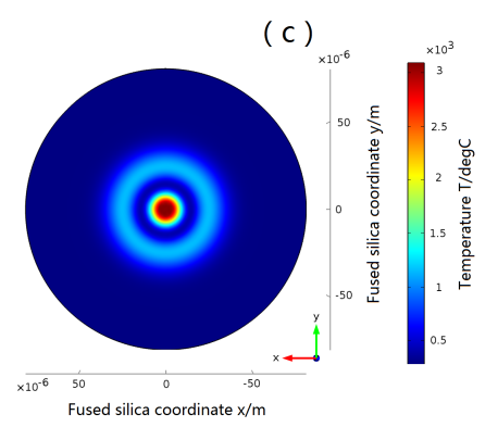
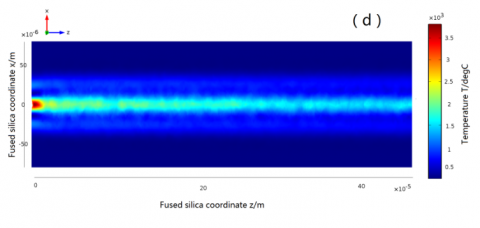
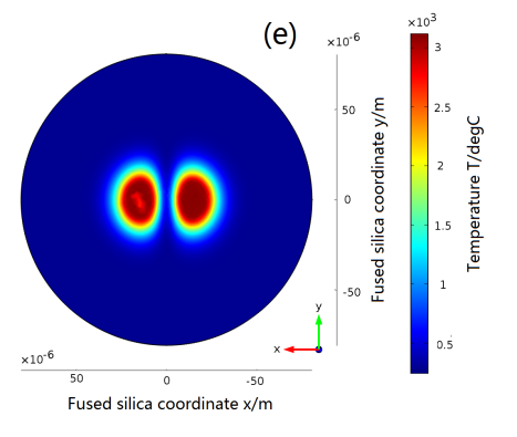
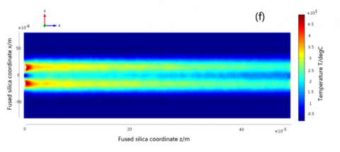
Figure 1 is the distribution of the temperature of fused silica at the time point t=2.14220$\mu s$ after going through six laser pulses under the radiation of different modes of Laguerre Gaussian laser. It can be seen from the figure that the distribution of temperature is basically consistent with the spatial distribution of the laser intensity. Since the vaporization on the material surface takes away partial heat, the temperature of the material surface remains near the vaporization temperature point. In the beam incidence direction, the temperature of the part near the surface is higher than the vaporization temperature due to the laser transmission. However, as the beam weakens in the material, the internal temperature of the material decreases rapidly.
Figure 1. Temperature distribution of fused silica radiated by different modes of laser beams
Notes: (a) TEM00, profile: z=0; (b) TEM00, profile: y=0 (c) TEM01, profile: z=0; (d) TEM01, profile: y=0; (e) TEM10, profile: z=0; (f) TEM10, profile: y=0
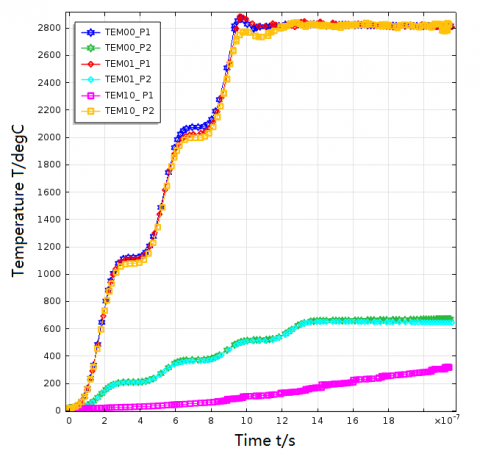
The sampling points P1(0, 0, 0) 20mm and P2(20, 0, 0) 20mm on the material surface are selected. The simulated calculation on the temperature variation under the laser pulse action is simulated, and the results are obtained through adopting three different modes of laser beams, namely, TEM00, TEM01 and TEM10, which are shown in Figure 2. Among them, TEM00_P1, TEM01_P1 and TEM10_P1 represent the temperature variation curves of P1 point under the action of three different modes of laser beams respectively and TEM00_P2, TEM01_P2, TEM10_P2 refer to the temperature variation curves of P2 point under the action of three different modes of laser beams respectively. The figure indicates that before the temperature of P1 point and P2 point reaches the vaporization point, their temperature variation curve is similar to the integral curve of the time distribution curve of the laser pulse. The temperature rises significantly in the first half cycle of the laser pulse and changes slowly in the second half cycle. Meanwhile, since the heat is not transmitted in time to the surroundings, the heat is accumulated. The coming of the second laser pulse makes the quartz temperature rise constantly. During the process of irradiation of the laser pulses of TEM00 and TEM01 modes, the temperature of P1 point reaches the material’s vaporization temperature, which leads to the material ablation and vaporization. Since the vaporization takes away partial heat, the temperature of P1 point did not rise significantly under the irradiation of the several subsequent pulses and remained at the temperature of the vaporization point suggesting that the results obtained when k=107 in the vaporization and ablation model are basically consistent with the simulation results. Due to the difference of the light spatial intensity distribution, the position of P2 point is far from the energy concentration area of the TEM00 and TEM01 modes of beams and its temperature rises slowly. When vaporization has occurred to the central area, because of the energy loss, the temperature of P2 point will not rise basically. The intensity of the TEM10 beam is distributed at the P2 position, so the energy is relatively concentrated, while the energy density of position P1 is low. Therefore, vaporization occurs at point P2 under the irradiation of six consecutive TEM10 mode of laser pulses, while the temperature at point P1 rises slowly.
Figure 2. Temperature variation of the fused silica at the sampling points
4.2 Change of the vaporization and ablation boundary of the fused silica
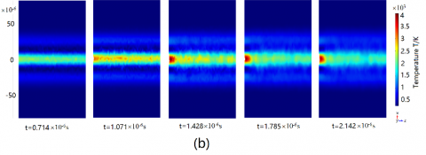
Figure 3 shows the ablation boundary morphology of the fused silica at different time points under the irradiation of TEM00, TEM01 and TEM10 Laguerre Gaussian laser beams. The sampling time is respectively corresponding to the time when the second to the six pulses terminate.
It can be seen from Figure 3 that vaporization did not occur after the fused silica passes through the first two pulses, because the surface temperature of the material has not reached the vaporization temperature and there is no change to the material boundary. After the fused silica passes through the third pulse, the temperature reaches the vaporization temperature. The vaporization occurs and the material boundary also changes. The ablation area and depth continuously expand with the constant irradiation of the laser pulse. Due to the difference of the light distribution of TEM00, TEM01 and TEM10 modes of laser beam, the vaporization and ablation areas are different. Under the TEM00 mode of light beam, the light distribution is intensified and the material ablation is obvious. Under the TEM01 mode, although the temperature rises in the annular region, due to the low Illumination intensity, the vaporization temperature is not reached and no material surface ablation is caused. Under the TEM10 mode, since the light intensity focuses on two areas, there are two vaporization and ablation area on the surface of the material.
Figure.3 Change of the vaporization and ablation boundary of the fused silica with time under the irradiation by different modes of laser beams
Notes: (a) TEM00, profile: y=0, (b) TEM01, profile: y=0; (c) TEM10; profile: y=0
Using the multi-physics field simulation tool, COMSOL has simulated the action of the Laguerre Gaussian beam and the fused quartz in different modes. This paper simulates the interaction between the Laguerre Gaussian laser beams of different mode and the fused silica using the multi-physics field simulation tool COMSOL. The simulation results show that the irradiation of different types of Laguerre Gaussian beams to the fused silica may cause damages to different areas of the material. After the fused silica passes through the irradiation of multiple pulses, its surface temperature reaches the vaporization temperature, which will cause the ablation and vaporization damage to the material. The morphology change of the vaporization and ablation boundary of the fused silica at different time point of irradiation can be figured out using the vaporization and ablation model.
[1] Feit M.D. (2002). Mechanisms of CO2 laser mitigation of laser damage growth in fused silica, Proceeding of SPIE, Vol. 4932, pp. 91-102.
[2] Yoshida K. (2012). Influence of beam spatial distribution on the laser damage of optical material, J Appl Phys, Vol. 49, No. 8, pp. 3815–3819.
[3] Norton M.A. (2004). Growth of laser initiated damage in fused silica at 1053 nm, Proceeding of SPIE 2004, Vol. 5647, pp. 197-205.
[4] Suratwala T.I. (2011). HF-based etching processes for improving laser damage resistance of fused silica optical surfaces, Journal of the American Ceramic Society, Vol. 49, No. 2, pp. 416-428.
[5] Yu J.X. (2012). Simulation on stress control of laser irradiated fused silica on ANSYS, Journal of University of Electronic Science and Technology of China, Vol. 41, No. 6, pp. 870–874. DOI: 10.3969/j.issn.1001-0548.2012.06.011
[6] Wei C.Y. (2005). Study of thermal behaviors in CO2 laser irradiated glass, Optical Engineering, Vol. 44, No. 4, pp. 870–874.
[7] Li S.X. (2016). Research on the temperature and thermal stress of fused silica irradiated by a laser pulse, LASER & INFRARED, Vol. 46, No. 7, pp. 786-791. DOI: 10.3969/j.issn.1001-5078.2016.07.002
[8] Li Y. (2012). Accumulation in high repetition rate femtosecond laser micromachining and its applications, Ph.D. dissertation, Department of Precision Instrument and Optoelectronic Engineering, Tianjin University, Tianjin, China.
[9] Li X.L. (2016). Finite element simulation of damage characteristics of CCD detectors under single-laser-pulse irradiation, LASER TECHNOLOGY, Vol. 40, No. 5, pp. 730-733. DOI: 10.7510/jgjs.issn.1001-3806.2016.05.023
[10] Jiao J.K. (2007). Temperature distribution of moving quartz glass heated by CO2 laser, High Power Laser and Particle Beams, Vol. 19, No. 1, pp. 1-4.
[11] Heat Transfer Module User’s Guide (2013). COMSOL Co., Ltd., Sweden.
[12] Jiang Y. (2012). Theoretical and experimental studies on surface damage repair of fused silica optical components, Ph.D. dissertation, Department of Physical Electronics, University of Electronic Science and Technology of China, Chengdu, Sichuan, China
[13] Grigoropoulos C.P. (2009). Transport in Laser Microfabrication, Cambridge University Press, New York, USA, pp. 60–84.
[14] Gao Y.H. (2011). Research on beam shaping for high-order Gaussian Beam, Optics &Optoelectronic Technology, Vol. 9, No. 5, pp. 61-64.
[15] Qin S.J. (2002). Micromachining of complex channel systems in 3D quartz substrates using Q-switched ND: YAG laser, Applied Physics A, Vol. 76, No. 6, pp. 773-777.
[16] Li S.X. (2012). Research on the fabrication of micro channels in fused silica substrates by nanosecond laser, Laser &Optoelectronics Progress, Vol. 49, No. 2, pp. 1-6. DOI: 10.3788/LOP49.041401
[17] Zhai L.B. (2006). The microfabrication of microchannel on glass with frequency tripled ND: YAG laser, Applied Laser, Vol. 26, No. 6, pp. 365-368.
[18] Li S.X. (2012). Study on the machining mechanism of fabrication of micro channels in fused silica substrates by laser-induced plasma, Acta Phys. Sin, Vol. 61, No. 11, pp. 1-8.
[19] Katsuichi U. (2003). Analysis of laser drilling process for substrate by optical simulation rectified at the ablation rate, Proceeding of SPIE, Vol. 5063, pp. 407-410.