OPEN ACCESS
At the present work modeling and improving the efficiency of a solar absorbing chiller system with a cylindrical phase change material (PCM) and nano-fluid is investigated. First, the absorbing chiller cycle is modeled by using the thermodynamic principles; after that, this model is changed to a standard mathematical planning model by using exergy analyses. Second, the mathematical model is optimized by a genetic algorithm and the optimum parameters of the cycle are calculated. The decision variables for optimization of the subsystem are the generator, the evaporator and the condenser temperatures. Finally, a cylindrical system of the PCM for storage of the thermal energy of the sun is designed by using the technique of thermal storage based on the enthalpy and finite volume method; the operation of the system is investigated.
exergy, genetic algorithm, optimization, storage system, finite volume method
Nowadays, development of a new and renewable energy potential is one of the main needs of the global community. Renewable energy is one of the most effective tools we have in the fight against climate change. For global warming problem, there are several protocols. The Montreal Protocol is an international treaty governing the protection of stratospheric ozone, originally signed in 1987. The Kyoto Protocol is an international agreement on the reduction of greenhouse gas emissions and on mechanisms aimed at cutting the costs of reducing emissions, in order to address possible changes in the climate. Two reasons can be broached for increasing these types of energies; first, decreasing the amount and level of fossil fuels and second, destructive environmental effects of fossil fuels. One of these kinds of energies is solar energy that currently is used in small scale (e.g. photovoltaic systems) and large scale (e.g. thermal systems) in different countries. Researchers obliged to fulfill a wide investigation of using this kind of energy on large industrial scales in addition to small scales. Some of these studies have been done and some of them have been presented in the related references [1, 2]. Absorption systems use energies such as the solar energy, the geothermal energy and the energy of industrial instruments for heating the generator. These systems have high potential to save energy consumption and low-pollutant of the environment. First, Misra et al. [3] used concept of optimization in LiBr-water absorption refrigeration system. They determined the average cost per unit exergy of all internal flows. Li and Sumathy [4-5] experimentally investigated a solar-powered absorption air conditioning system of LiBr-water solution as their working refrigerant. The results showed that using a hot-water storage tank is necessary to enhance the reliability of the system. Atmaca and Yigit [6] developed a modular computer program for a solar-powered single-effect absorption chiller by using the lithium bromide-water as the working fluids. They investigated various parameters for the different cycle configurations at Turkey. Sayegh [7] investigated a solar-powered absorption cooling system by using a thermal storage tank, an auxiliary heater and a flat plate solar collector for the weather conditions at Syria. A numerical study was carried out on the single-effect lithium bromide/water absorption systems and the energy analysis was presented by Talbi and Agnew [8] and Şencan et al. [9]. Infante Ferreira and Kim [10] investigated the different technologies to convert solar energy into the cooling effects. They concluded that parabolic collectors have the lowest collector area investment between all considered absorption cases in combination with a double-effect H2O/LiBr absorption system. Sayadi et al. [11] investigated the performance optimization of solar driven small-cooled absorption–diffusion chiller with light hydrocarbons. Falahatkar and Akhavan [12] studied thermodynamic and analysis of a solar hot-water single-effect chiller in Tehran. Since there isn’t any research in the field of cooling by absorption chiller with phase change material (PCM) and optimization of this cycle, so this study is aimed to investigate such problem [13-14].
Phase Change Materials (PCMs) are ideal products for thermal management solutions. This is because they store and release thermal energy during the process of melting & freezing (changing from one phase to another). When such a material freezes, it releases large amounts of energy in the form of latent heat of fusion, or energy of crystallisation. Conversely, when the material is melted, an equal amount of energy is absorbed from the immediate environment as it changes from solid to liquid. This property of PCMs can be used in a number of ways, such as thermal energy storage whereby heat or coolness can be stored from one process or period in time, and used at a later date or different location. PCMs are also very useful for different applications, for example in providing thermal energy for generator of an absorption chiller during the night.
Nanofluids are a new class of fluids engineered by dispersing nanometer-sized materials (nanoparticles, nanofibers, nanotubes, nanowires, nanorods, nanosheet, or droplets) in base fluids. In other words, nanofluids are nanoscale colloidal suspensions containing condensed nanomaterials. They are two-phase systems with one phase (solid phase) in another (liquid phase). Nanofluids have been found to possess enhanced thermophysical properties such as thermal conductivity, thermal diffusivity, viscosity, and convective heat transfer coefficients compared to those of base fluids like oil or water. It has demonstrated great potential applications in solar purposes and other fields.
In this paper at the first step, thermodynamic modeling and exergy analysis were carried out in lithium-bromide absorption chiller cycle and then principal parameters of cycle were optimized by genetic algorithm. In the second step, specifications of collector and also PCM were assigned. Finally, by focusing on the time of using absorption chiller, temperature changes of PCM and nano-fluid as High Temperature Fluid (HTF) were discussed in terms of time.
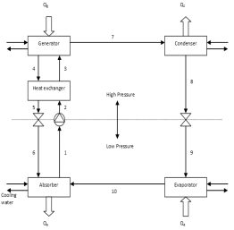
The present study is aimed at designing a solar-powered absorption cooling system for a building with cooling load equal to 84.4 kW in Tehran, Iran. For more detailed about load calculations readers can be refer to reference [12]. Operation-time of the Single Effect Absorption Chiller (SEAC) system is considered 12 hours and 8 hours was related to day and 4 hours was allotted to night. The period of operation-time of this system is considered 6 months of year (from May 15th to October 15th). A schematic diagram of SEAC was shown in figure 1. This system includes an evaporator and absorber tower on the low-pressure side, a generator and a condenser on the high-pressure side. Working fluids are water as refrigerant and LiBr as absorbent.
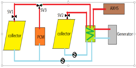
For the solar absorption chiller, the effective and economic daily thermal energy storage is unavoidable, because the solar energy is unavailable during certain periods of the day and the night. For this reason, at the SEAC system for providing of needed heat of generator, solar collector with thermal energy storage system (PCM) is considered. According to figure 2, 40% of the thermal energy of the generator and the thermal energy to the melting point of PCM are provided by the solar energy and the remaining amount (60%) is provided by the Auxiliary Heating System (AXHS) through the day. During the day, the electric valves "SV1, SV3 (between collector and PCM) and SV2" (between collector and generator) are open. In night, the electric valve "SV3" (between PCM and generator) is open and electric valves "SV2", and "SV1" are closed. In order to operate SEAC system, providing hot water with $88^{\circ} \mathrm{C}$ temperature at input of generator is important. During the night input temperature of HTF to PCM is equal to $35^{\circ} \mathrm{C}$ and this temperature increases by the storage thermal energy of PCM until $50^{\circ} \mathrm{C}$ and the remained thermal energy (from $50^{\circ} \mathrm{C}$ to $88^{\circ} \mathrm{C}$ ) will be provided by AXHS. It is needed to mention that, storage heat in PCM during the charging time (day) is equal to the removal heat of PCM during the discharge time (night).
Figure 1.Schematic of single effect absorption chiller
For modeling, some assumptions are considered:
1) All processes are at the steady state conditions,
2) Exit solution of generator and absorbent, exit fluid of condenser and evaporator are at the saturation state conditions, and
3) Valves operate at an isenthalpic process.
Figure 2. Schematic of collector and PCM.
The coefficient performance of the cooling system (cooling COP) is defined as the ratio of the heat extracted from the evaporator to the total work of the pump and input heat to the generator that is defined as follows:
$C O P_{c o o l}=\frac{Q_{E}}{Q_{G}+W_{P}}$ (1)
Energy equation balance for the total cycle of SEAC system is presented as follows:
$Q_{E}+Q_{G}-Q_{A}-Q_{C}+W_{P}=0$ (2)
According to analysis of exergy, the aim is to obtain exergy destruction for each component of this system $\left(E_{D, k}\right)$ in which $k$ index is referred to each components of this system i.e. evaporator, condenser, absorber tower, heat exchanger of solution and pump. Exergy equation balance of SEAC system can be defined as follows [8]:
$\sum \dot{E}_{in, k}-\sum \dot E_{o u t, k}- \dot Q_{k}\left(1-\frac{T_{0}}{T_{k}}\right)-\dot W_{k}-\dot E_{D, k}=0$ (3)
For more detailed about modeling of the absorption chiller readers can be refer to reference [12].
3.1 Thermodynamic analysis and optimization
(a)
(b)
(c)
(d)
(e)
(f)
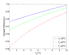
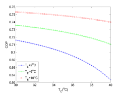
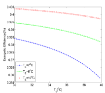
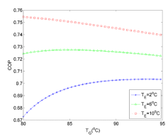
Figure 3. Variation of COP and exergetic efficiency versus evaporator, generator and absorber temperatures
Table 1. The best values of decision variables to have the highest value of COP and exergetic efficiency based on SO and MO optimization.
|
Component |
Base (0C) |
Single Objective optimization Based on |
Multi Objective optimization Based on |
|
|
COP |
Exergetic efficiency |
COP & Exergetic efficiency |
||
|
Absorber |
37.8 |
30(0C) |
30(0C) |
30.2 |
|
Evaporator |
7.2 |
10(0C) |
10(0C) |
8.4 |
|
Condenser |
37.8 |
30(0C) |
30(0C) |
33.33 |
|
Generator |
87.8 |
80(0C) |
80(0C) |
80.2 |
By considering the first and second laws of thermodynamic, the effects of evaporator, condenser, and generator temperatures on COP and exergetic efficiency of SEAC system are investigated and results have been shown in figure 3. For more details about concept and proceed of optimization by genetic algorithm readers can refer to references [3, 11]. Regarding the thermodynamic modeling of SEAC, it was concluded that by increasing evaporator temperature, COP and exergetic efficiency will be increased (Figs. 3 (a), (b)), but by increasing condenser temperature, COP and exergetic efficiency will be decreased (Figs. 3 (c), (d)). Based on figures 3 (e, f), it can be seen that by increasing generator temperature, COP and exergetic efficiency will be increased and then decreased. After investigation the effect of each parameter, the highest value of COP and exergetic efficiency is obtained by genetic algorithm at single-objective (SO) and multi-objective (MO) optimization cases. At this step, the optimized operating point of SEAC system is obtained from COP and exergetic efficiency. According to SO optimization results, the maximum value of COP will be equal to 0.778, and also the temperature of the evaporator, the condenser, the generator, and the absorber in COP mode are $10,30,80$ and $30^{\circ} \mathrm{C}$ , respectively. Heat exchanger efficiency is considered equal to 0.8. Optimum efficiency of exergy is 0.423 for SO optimization and the temperature of evaporator, the condenser, the generator and the absorber in exergetic efficiency mode are $10,30,80,30^{\circ} \mathrm{C}$ , respectively. By synchronic optimization of the exergetic efficiency and COP (MO), the values of these parameters will be 0.417 and 0.769, respectively. Temperature of the evaporator, the condenser, the generator and the absorber in multi-objective optimization are $8.4,30.2,80.2$ and $30.33^{\circ} \mathrm{C}$ , respectively.
Table 1 shows the best values of the decision variables to achieve the highest value of COP and exergetic efficiency based on SO and MO optimization. According to the optimum operative conditions based on MO results, the cooling capacity is evaluated equal to 84.48kW and generator power is calculated equal to 118.45kW. According to the cooling capacity (84.48 kW) and the generator power (118.45 kW), 47.38 kW of this thermal energy is provided by the solar collector and 71.07 kW of it will be provided by AXHS.
3.2 Thermal storage system and PCM selection
Table 2. Thermophysical properties of PCM and HTF in this work
|
property |
value |
unit |
|
Melting point of PCM |
117.7 |
$^{\circ} \mathrm{C}$ |
|
Melting Latent heat of PCM |
339.8 |
$k J k g^{-1}$ |
|
Specific heat of PCM (Liquid) |
2.76 |
$k J k g^{-1} K^{-1}$ |
|
Specific heat of PCM (Solid) |
1.38 |
$k J k g^{-1} K^{-1}$ |
|
Conductivity of PCM (Liquid at 140 $^{\circ} C$) |
0.326 |
$W m^{-1} K^{-1}$ |
|
Conductivity of PCM (Solid at 25 $^{\circ} C$) |
0.733 |
$W m^{-1} K^{-1}$ |
|
Density of PCM (Liquid at 140 $^{\circ} C$) |
1300 |
$k g m^{-3}$ |
|
Density of PCM ( Solid at $25^{\circ} \mathrm{C}$) |
1480 |
$k g m^{-3}$ |
|
Conductivity of HTF |
0.756 |
$W m^{-1} K^{-1}$ |
|
Specific heat of HTF |
3.879 |
$k J k g^{-1} K^{-1}$ |
Among the various methods of the energy storage, the latent heat of the thermal energy system using PCM, because of its high energy storage density and its ability to provide heat at a constant temperature, is quite operational. Main system at figure 2 is assumed to be used during the hours from 9 AM to 9 PM. Operation of this system is provided from 9 AM to 5 PM by the collector using the solar energy, but storage energy system (SES) supports it during 5 PM to 9 PM. This duration refers to a time that the collector does not receive sufficient solar radiation. The PCM used in the design of the thermal storage systems should possess desirable thermo-physical, kinetic, and chemical properties and also access a melting temperature near the working temperature of the main system. Working temperature of the main system in this study which was provided by the collector and the storage system is $88^{\circ} \mathrm{C}$ . So, the suitable PCM used for this investigation is considered “Erytrol”. Table 2 shows the thermo-physical properties of PCM and HTF.
The problem of the phase change falls into the category of moving boundary problems. Solving this problem is carried out by enthalpy method. In this method, the governing equation is divided into three states (liquid, mushy and solid) as each of them has individual governing equation. Here, by using the storage system with PCM, considering the heat of generator provided by the solar collector is necessary. The thermal energy to the melting case of PCM "62 kg" (Erytrol), which is inside the storage pipe "50", is provided by HTF and it is noticeable that its melting temperature is equal to $117.7^{\circ} \mathrm{C}$ . Solid PCM is liquefied and then it will be prepared in order to giveback heat and also provide the thermal energy of generator along the night.
3.3 Collector specifications and discharge time
The main section and the heart of solar system is a solar collector which transfers thermal energy to the working fluid by absorbing the solar radiation energy and exchanges it to the heat. It is noticeable that required energy of the generator is obtained from the previous sections by considering the synchronic optimization of COP and the exergetic efficiency. Due to the location of Iran (on the north, 25-45 degrees latitude), the average solar energy is about ( 5.3 $\mathrm{kWh} / \mathrm{m}^{2}. \mathrm{day}$ ) 19.23 $\mathrm{MJ} / \mathrm{m}^{2}$ on horizontal surface. In this country, the sunny hours are more than 2800 hours in a year and also the government’s policy in order to develop the energy production by new technique indicates the high potential of Iran using solar energy for different purposes. Based on the NASA data, the average solar radiation intensity in July at Tehran is equal to $7.5 \mathrm{kWh} / \mathrm{m}^{2} .$ day on horizontal surface. By assuming 9 hours radiation at this month of summer, the amount of monthly solar radiation on the horizontal surface is equal to $G=834 \mathrm{W} / \mathrm{m}^{2}$ . This power of monthly solar radiation is used for calculating the input thermal energy to the collector. It is noticeable that based on information collected from different papers, the angle of the collector on south side is considered 36 degree which is about Tehran’s latitude. By considering the below equation, the heat gained by the collector can be calculated as follows:
$q_{\text {collector}}=F_{R}(\tau \alpha)_{\alpha v e} . G-F_{R} U_{L} \Delta T$ (4)
For the collector with the vacuumed pipe, FRULvalue is about 0.7 and $F_{R}(\tau \alpha)_{a v e}$ is about 0.689 [12]. Mass flow rate of HTF is calculated by using the optimum amount of $Q_{\text {gen }}$ and we can assign the required surface of solar collector. To calculate the efficiency of the collector, the following equation is given:
$\eta_{\text {collector}}=\frac{q_{\text {collector}}}{G_{t}}$ (5)
HTF in the thermal storage section provides required heat for melting the solid "PCM". The total thermal energy transferred by HTF is equal to 132.51 $\mathrm{kW}$ . By considering this subject as the output power to collector area is equal to 541.35 $\mathrm{W} / \mathrm{m}^{2}$ and needed area of the collector will be equal to 242.76 $\mathrm{m}^{2}$ . Finally, by considering the collector surface and the absorbent surface of each vacuum pipe which is equal to 0.0804 $\mathrm{m}^{2}$ , the number of the vacuum pipe will be calculated. Each of collectors has 22 pipes, therefore for this system it is clearly that, 138 collectors and 3014 vacuumed pipes are needed. Also, the value of the collector efficiency will be equal 64.9%. The time of PCM charging equals 8 hours is assumed. Now, since the mass flow rate of HTF provides the required thermal energy for melting of PCM, the storage thermal energy of PCM increases the temperature of HTF from $35^{\circ} \mathrm{C}$ to $50^{\circ} \mathrm{C}$ during the night. Also, the discharging time of PCM based on the time of charging and mass flow rate of HTF during the night must be considered. As shown in figure 4, it is clearly that the reaching time of HTF to $50^{\circ} \mathrm{C}$ temperature is equal to 400 minutes after operating the thermal discharge. The period of discharging time of PCM and attaining / reaching time to the temperature of $50^{\circ} \mathrm{C}$ were shown in figure 4.
Figure 4. Variation of HTF and PCM temperature versus time.
In the first step, the thermodynamic modeling and the exergy analysis in the lithium-bromide absorption chiller cycle has been carried out and then, the principal parameters of cycle have been optimized by a genetic algorithm. In the second step, the type of collector and the mass of phase changing material have been assigned. Finally, by focusing on the time of using absorption chiller, the temperature changes of HTF and PCM are being discussed along the time. It should be noted that during the discharging time, the storage thermal energy of PCM transmits to HTF. It is clearly shown that attaining/reaching time of HTF to $50^{\circ} \mathrm{C}$ is equal to 400 minutes after the operating thermal discharge.
|
SYMBOLES |
|
|
COP |
Coefficient of performance (-) |
|
E |
Exergy, (kJkg-1) |
|
ED |
Exergy destruction, (kJkg-1) |
|
FR |
collector heat removal factor |
|
G |
monthly solar radiation on the horizontal surface, (Wm2) |
|
h |
Enthalpy, (kJkg-1) |
|
UL |
collector overall heat loss coefficient, (Wm-2) |
|
$\alpha$ |
absorption coefficient of plate |
|
$\tau$ |
transmission coefficient of glazing |
|
$\eta_{\text {collector}}$ |
collector efficiency, (%) |
|
qcollector |
collector heat output, (W) |
[1] Sidiras D.K., Koukios E.G. (2003). The solar thermal market in Greece-review and perspectives, Renewable and Sustainable Energy Reviews, Vol. 7, pp. 397-418.
[2] Schlaich J., Bergermann R., Schiel W. (2005). Design of commercial solar updraft tower systems- utilization of solar induced convective flows for power generation, Journal of Solar Energy Engineering, Vol. 1, pp. 117-124.
[3] Misra R.D., Sahoo P.K., Gupta A. (2005). Thermoeconomic optimization of a single effect vapor absorption refrigeration system, Journal of Energy Resources Technology, Vol. 26, pp. 158-169.
[4] Li Z.F., Sumathy K. (2001). Simulation of a solar absorption air conditioning system, Energy Conversion and Management, Vol. 42, No. 3, pp. 313-327.
[5] Li Z.F., Sumathy K. (2001). Experimental studies on a solar powered air conditioning system with partitioned hot water storage tank, Solar Energy, Vol. 71, No. 5, pp. 285-297.
[6] Atmaca I., Yigit A. (2003). Simulation of solar-powered absorption cooling system, Renewable Energy, Vol. 28, No. 8, pp. 1277-1293.
[7] Sayegh M.A. (2007). The solar contribution to air conditioning systems for residential buildings, Desalination, Vol. 29, pp. 171-176.
[8] Talbi M.M., Agnew B. (2000). Exergy analysis: an absorption refrigerator using lithium bromide and water as the working fluids, Applied Thermal Engineering, Vol. 20, pp. 619-630.
[9] Şencan A., Yakut K.A., Soteris A. (2005). Exergy analysis of lithium bromide/water absorption systems, Renewable Energy, Vol. 30, pp. 645- 657.
[10] Infante Ferreira C.A., Kim D.S. (2014). Techno-economic review of solar cooling technologies based on location-specific data, Int. J. Refrig., Vol. 39, pp. 23–27.
[11] Sayadi Z., Thameur N.B., Bourouis M., Bellagi A. (2013). Performance optimization of solar driven small-cooled absorption–diffusion chiller working with light hydrocarbons, Energy Conversion and Management, Vol. 74, pp. 299–307.
[12] Falahatkar A., Akhavan H. (2014). Design and simulation of a single effect LiBr–H2O absorption chiller for a building in Tehran, Energy Journal of Iran, Vol. 14, pp. 37–46.
[13] Mirandola A., Lorenzini E. (2016). Energy, environment and climate: from the past to the future, International Journal of Heat and Technology, Vol. 34, No. 2, pp. 159-164. DOI: 10.18280/ijht.340201
[14] Casano G., Piva S. (2015). Parametric analysis of a PCM energy storage system, International Journal of Heat and Technology, Vol. 33, No. 4, pp. 61-68. DOI: 10.18280/ijht.330408