OPEN ACCESS
This paper is a preliminary step through an effective redesign of valved pulsejet. This redesign activity relates to both thermodynamics and heat transfer. It aims to overcome their intrinsic limits: short service life of the valves and low energy efficiency of the Lenoir cycle. A detailed analysis of the operative behavior of pulsejets allowed the authors to advance an effective hypothesis about redesigning this propulsion system. A preliminary bibliographic analysis shows that the very high temperature that the walls of the combustion chamber reaches does not allow the use of more effective valves with respect to the petal valves or grid mounted reed valves. The absence of any compression, which is a characteristic property of the Lenoir cycle, is the main cause of the low thermodynamic efficiency of the system. The intrinsic fragility of these valve systems has blocked any further development of the valved pulsejet. A preliminary feasibility analysis of a cooling system, which can be used on pulsejets, is then a preliminary element both in the direction of improving both their thermodynamic performance and their robustness. The considered working conditions are: temperature of 1500 K, which oscillates with an amplitude ±500 k and a frequency of 30 Hz. The refrigerant is considered water and its average temperature is supposed 80 ºC. Analysis of the temperature profile within the wall and the effects of the oscillations of gas temperature have been evaluated, together with a preliminary design of the cooling system.
Pulsejet, Cooling, Oscillating temperature, Thermal shocks, Lenoir cycle, Efficiency.
1.1 Generalities
Pulsejet is a jet engine in which combustion occurs in pulses without any initial compression. It is currently realized in two fundamental architectures [2]. They are valveless pulsejets, which have single tube architecture without moving parts and valved pulsejets, which have a simple valve system actuated by variations in pressure difference.
Pulsejet engines are simple, lightweight, and low cost jet propulsion systems. They are capable of running statically (i.e. they do not need to have air forced into inlet by forward motion). Otherwise, they are afflicted by poor compression ratio and low specific impulse. They operate according to Lenoir cycle [3], which is characterized by the absence of any compression process. Consequently, it has a much lower thermal efficiency than Otto and Diesel cycles [4].
If a valved pulsejet is considered, the effects of pulsation and high temperatures create evident problems related to the robustness of petal or Reed valves. They generate evident accelerated fatigue stresses, which appears the main cause of these failures. This paper is a preliminary necessary part of the study through new pulsejet architectures with improved performances. It analyses the possibility of both operating according to more efficient thermodynamics cycles with some pressurization and increasing the service life of the valves. These objectives require cooling the combustion chamber of a pulsejet in order to allow that implementation of pressurization system and different and more robust valve systems that can ensure higher affordability. The research activity that is still in a very preliminary phase is expected to produce major step advancements in terms of both higher energy efficiency and increased affordability even in the case of using hydrogen as system fuel. In particular, this research activity aims to produce the design of a new and more effective family of subsonic pulsejets and does not aim to compete with ramjets or Pulse Detonation Engines, which operate in supersonic conditions.
1.2 History of pulsejet
Pulsejet is probably the oldest concept of jet propulsion. Early attempts to utilize the power obtained from explosions for propulsion date back to late 17th–early 18th centuries [5]. In this period it has been discovered the velocity of propagation of combustion modes [6], also in long tubes even when gas was ignited by non-explosive means (spark or open flame). In this case, flame acceleration along the tube, often accompanied with flame speed oscillations, was detected prior to onset of detonation. A fundamental result is discovering that the detonation velocity are not affected by the ignition source and tube diameter, but are only a function of the explosive mixture composition.
The mechanism of detonation propagation has been identified as governed by adiabatic compression of the explosive mixture rather than by molecular diffusion of heat [7], which implies the development of high pressure propagating waves. During those times, the interest in detonation was associated with explosion prevention in coalmines. Mikhelson in 1890, Chapman in 1899, and Jouguet in 1904, provided theoretical estimates for the detonation parameters based on one-dimensional (1D) flow considerations and mass, momentum and energy conservation laws by the shock wave theory of Rankine and Hugoniot. These simple models describe detonation waves as a pressure discontinuity coupled with the reaction front (instantaneous reaction) and present a good agreement with observed detonation velocities.
A significant progress has been obtained at the beginning of the 20th century involving in both experimentation and analysis of detonations. This historic period has allowed the development of new solutions dealing with new technologies, balloon transportation, and reciprocating internal combustion engines [8]. In 1913, Lorin designed the first subsonic pulsejet, which would have been somewhat more efficient, but he had no way to achieve high enough speeds for it to operate, and the concept remained theoretical for quite some time. Fonó in 1915 presented a solution for increasing the range of artillery, comprising a gun-launched projectile, which was to be united with a ramjet propulsion unit. This invention has been intended to allow launching heavy projectiles with long range and low initial velocity from lightweight guns.
Figure 1. Fieseler Fi 103 - V1 Bomb
But the historic milestone of pulsejet research has been the German Fieseler Fi 103 (V1 middle range bomb) [9, 10], which was propelled by Argus As 014 pulsejet, which is based on the 1928 activity on a new design of a pulsejet engine by Paul Schmidt. In 1934, along with Professor Georg Madelung, Schmidt proposed a “flying bomb” to be powered by his pulsejet and in 1938, they demonstrated that a pulse jet–powered unmanned bomber could be realized even if the prototype lacked range and accuracy and was expensive to construct. Further developments of this project allowed developing the Argus engine [11], which equipped the Feiseler Fi 103 bomb.
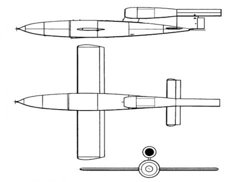
Figure 2. Schema of Argus As 014 pulsejet that equipped Fieseler Fi 103 V1 bomb
After WW II the pulsejet has been partially abandoned in favour of other architectures, because of vibration induced problems, terrible acoustic impacts, lower thrust specific fuel consumption. On the other side, they have significantly simpler mechanics, which is costless, and demonstrated excellent operating characteristics. Derived concepts such as ramjets and scramjets achieved a higher success level because of their higher performances.
1.3 Preliminary assumptions
The inside is exposed to burning gases with an average temperature of 1500 K, oscillating 500 K at 30 Hz. Inside the chamber it has been assumed a convective coefficient in line with values of ICE (Internal Combustion Engine): U = 1000 W/(m2·K) including radiation transfer [12, 13]. The outside is exposed to cooling water at 353 K, with a convective coefficient of 5000 W/(m2·K) [14, 15]. In addition, this case is in line with the values assumed for ICE. The wall is supposed made of stainless steel 1 mm thick with the following values of conductivity:
$k=\left\{\begin{array}{l}{25^{\circ} C \rightarrow 16 W /(m K)} \\ {125^{\circ} C \rightarrow 17 W /(m K)} \\ {225^{\circ} C \rightarrow 19 W /(m K)}\end{array}\right.$
Dimension of the pulsejet have estimated to be a cylinder with diameter 0.25 m and length 1.4 m, with a volume of 68 dm3 and combustion chamber about 20% of total volume.
2.1 General pulsejet analysis
The key advantage of pulsejets is its own higher simplicity with respect to any other propulsion system []. It is cheap and unsophisticated, and has fundamental economic advantages in the field of miniature propulsion eventually coupled with heat co-generation. The pulsejet thermodynamic processes can be approximated by the Lenoir cycle. The unsteady pulsating combustion does not happen at constant pressure such as in most of jet propulsion systems, but at almost constant volume [16]. Pulsejets burn fuel intermittently in a quick succession of detonating pulses. The consequent pressure shocks and formation of gaseous product of combustion produces the thrust of the system. It is important to notice that pulsejet has a very low thermodynamic efficiency related to the nature of the Lenoir cycle, but produces a net pressure gain between the air intake and the exhausts. The exhaust pressure is higher than the intake pressure. There is pressure gain across the combustor, rather than loss, without wasting the power generated by combustion, even if the combustion efficiency is lower with respect to other systems. This pressure gain, which is usually around 5%, produces some gain in combustion pressure with an improvement in terms of overall efficiency
The key problem is that the gain offered by pulsating combustion is difficult to be utilized for propulsion. The potential of pulsejet can be increased when it is used as a combustor for a turbine engine, because the pressure gain is multiplied in a high-pressure environment. If compared to traditional constant pressure combustors, pulsejets have smaller mechanical losses and lower fuel consumption or higher fuel efficiency. Pulsating behaviour creates problems of coupling with axial turbine blades. Radial turbines are more solid on this point of view but they have lower efficiency especially with intermittent flow.
2.1 Valved pulsejet architecture and problems
Today, pulsejet technology seems a viable source for alternative propulsion purposes in the subsonic velocity range. This paper present a preliminary activity in the direction of developing new pulsejet engines with much longer operative life with respect to the actual design of valved pulsejet.
Figure 3. Small pulsejets’ valve designs
Petal valve system is the most common and is used in small pulsejet engines. The petal valve system is created by some elements: a surface with drilled holes, a disk with valve petals that covers the holes. This system has a costless manufacturing process but had a low area of potential valve and gives optimal performances in small pulsejets. For this reason, the petal valve system is not used in large engines, but only if the thrust of engine is in the range between 1 to 5 kg. Applications up to 50 kg of static thrust have produced but they look inefficient and have low operative life.
Today valved pulsejets uses petal valves, which have short life spans. When subject to the extreme temperatures, pressures and very high frequency, tests performed at NASA Glenn [21] demonstrated that the valves last approximately fifty seconds.
Figure 4. High temperatures during a Lockwood-Hiller experiment
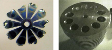
This is detrimental to pulsejet performance and hinders research efforts [22]. Below are two figures depicting a failed valve (left) and the valve head (right).
Figure 5. Failed valve (left) and valve head (right) [13]
The high-efficiency petal valve is similar to the regular petal valve system in that it is a circular array of valve holes, but uses valve plate area by adopting optimized and shaped valve holes. The optimized shape of the inlet holes increases the efficiency of the pulsejet and requires a smaller diameter combustion chamber for the same amount of thrust. In particular, this solution has reduced drag and better airflow through the engine. On the other side, it has higher costs because each valve hole must be machined to the correct shape and size, instead of simply drilling the hole. The applications range spaces from 1 to 50 kg.
Larger pulsejet engines adopt the valve grid system, which is directly derived from the original design of the Argus engine of the V1 bombs. A valve grid is a rectangular array of valve hole. However, unlike the previous types, the valve holes are not perpendicular to the side of the combustion chamber. The valves usually rest on a set of angled plates as seen in Figure 5. Valves are still reed valves with radial deformation and they are placed on inclined planes. The must have limited dimensions in order to seal correctly the combustion chamber. This architecture allows a more optimized fluid dynamic of the inlet section and a larger area of openings, and thus they have a smaller diameter of the combustion chamber and less aerodynamic drag. Usually this architecture is used for engines with a thrust above 20 kg and increases it competitiveness with increasing thrust.
Figure 6. Architecture and valve detail of a high thrust pulsejet based on the design of Argus 0.14
The thermodynamic cycle that best describes the pulsejet behaviour is the Lenoir cycle. It is composed by three phases [17]:
1-2: Constant volume (isochoric) heat addition;
2-3: Isentropic expansion with no heat interaction and production of work;
3-1: Constant pressure (isobaric) heat rejection with consume of some work.
Figure 7. PV and TS Diagram of Lenoir cycle
A preliminary evaluation according to the ideal model, which is reported in Appendix 1, allows calculating a total work of 490 kJ and consequent thrust can be evaluated to be about 25 kN assuming the specified frequency.
Fuel consumption can be approximately evaluated according to [18] and [19]. The volume of the combustion chamber is V = 39 dm3, f =50 Hz. Mass of explosive fuel/air mixture is about 0.04 kg. To burn this amount of air it is necessary about 0.0032 kg of fuel/explosion. It means 0.16 kg fuel/s. Assuming that the fuel is gasoline with a LHV of 43.4 MJ/kg it means that the energy introduced by mean of fuel is around 6.9 MJ/s with fuel efficiency around 7.1%. Assuming the combustible is Hydrogen it is necessary 0.00115 kg fuel / explosion. Those results show clearly that a serious improvement is necessary to make the pulsejet energetically competitive against other propulsion systems.
The improvement of thermodynamic performances relates directly to the development of new pulsejet designs that can keep the simplicity of pulsejets but can overcome the intrinsic limits, which have been verified. Some levels of major complexity will be accepted but they must be individually checked against their benefits in terms of both energy, performances and environmental. Guidelines for improving the energy efficiency necessarily consider different compression techniques, which can allow an effective increase of efficiency without loosing the periodic and subsonic nature of the system. The capability of producing also some mechanical energy at low cost will be considered a necessary element both for governing the valves and for producing some amounts of electrical energy which is necessary for the spark ignition and the aircraft system. Multistage systems with thrust augmenters will be considered favourably.
This direction of evolution will necessarily consider the definition of an appropriate cooling system because of the possible transfer of some state of the art technologies from the sector of internal combustion engines. This cooling system can be also modulated to be the energy source of appropriate coupled cogeneration systems because of the very high thermal efficiency of this propulsion system if compared to the very low specific thrust.
This paper is a preliminary part through an effective definition of new pulsejet architecture. For reaching this goal, it is preliminarily necessary to verify the effectiveness of cooling the combustion chamber of a pulsejet by modelling the heat transfer through the walls. It can be then possible to evaluate the average state of the temperature profile within the wall and the effect of the oscillations of gas temperature.
5.1 Steady state solution
First, the geometry and nomenclature is sketched in Fig. 1, together with the expected solution. Notice that a planar geometry is assumed because the wall thickness is assumed much smaller than the diameter of the cylinder. The planar approximation allows simplifying the average temperature profile within the wall, 0 < x < L by a linear function
$T(x)=T_{1} \cdot\left(T_{1}-T_{0}\right) \frac{x}{L}$(1)
The end values, and the unitary heat flux, are:
$\dot{q}=\frac{T_{g}-T_{w}}{\frac{1}{U_{g}}+\frac{L}{k}+\frac{1}{h_{w}}}$(2)
and
$\dot{q}=h_{w} \cdot\left(T_{2}-T_{w}\right)=\frac{k}{L} \cdot\left(T_{1}-T_{2}\right)=U_{g} \cdot\left(T_{g}-T_{1}\right)$(3)
from which
$\dot{q}=1150 k W$
that means for the specific geometry assuming an exchange area equal to 0.25 the external area of the pulsejet
$\dot{Q}=575 k W$
and T1=582 K, and T2=533.5 K.
5.2 Transient analysis
Transient analysis of the specific case is a complex problem also by mean of numerical simulation by mean of CFD or other codes because of its transient periodic nature. The simplest solution seems to be the analytical one, by integrating the heat equation considering a periodic boundary condition in a semi-infinite slab.
$\frac{\partial^{2} T}{\partial x^{2}}-\frac{1}{\alpha} \frac{\partial T}{\partial t}=0$(4)
A solution can be reached assuming that:
1. the thickness of the pipe is adequate
2. the high-frequency excitation produces only a small penetration depth of the oscillations.
This paper in particular does not look at the initial transient condition when the engine starts started. It focuses on the periodic solution when the system has reached the operating regime. The period is assumed t =1/30 s, and decays exponentially with a penetration xc. Those conditions lead to the following law of temperature:
$T(x, t)=C \exp \left(-x / x_{c}\right) \cos \left(2 \pi \cdot t / \tau-x / x_{c}\right)$(5)
By substituting this expression into heat equation, it results:
$2 C \frac{\alpha t-\pi x_{c}^{2}}{\alpha t x_{c}^{2}} \cdot e^{\left(-x / x_{c}\right)} \sin \left(\frac{2 \pi t}{\tau}-\frac{x}{x_{c}}\right)=0$(6)
and then
$x_{c}=\sqrt{\frac{\alpha \tau}{\pi}}$
and assuming t>>t it results
$\frac{T(x, t)-T_{0, \text {mean}}}{T_{0, \max }-T_{0, \operatorname{mean}}}=e^{\left(-x / x_{c}\right)} \cos \left(\frac{2 \pi t}{\tau}-\frac{x}{x_{c}}\right)$
where T0,mean and T0,max are the average and peak values of the temperature oscillation on the solid surface.
Instead of the solid-surface temperature, the far-field temperature in a fluid in contact with that surface is imposed,
$T_{\text {fluid}}(t)=T_{1, \text {mean}}+\Delta T_{1} \sin (2 \pi t / \tau)$
This equation can be solved by introducing a damping in surface-temperature amplitude and a phase-shift in the time response. They can be computed from the convective heat-transfer equation:
$h\left(T_{\text {fuid}}(t)-T(0, t)\right)=-k\left.\frac{\partial T(x, t)}{\partial x}\right|_{x=0}$
The temperature field within the solid can be expressed as a function of Biot number in line with Dumas and Trancossi [16, 17] former solution to a crossflow heat exchanger.
$\begin{align} & \frac{T(x,t)-{{T}_{0,mean}}}{{{T}_{0,\max }}-{{T}_{0,mean}}}\overset{t>>\tau }{\mathop{=}}\, \\ & =\frac{1}{\sqrt{1+\frac{2}{Bi}+\frac{2}{B{{i}^{2}}}}}\cdot {{e}^{\left( -x/{{x}_{c}} \right)}}\cdot \sin \left[ \frac{2\pi t}{\tau }-\frac{x}{{{x}_{c}}}-\arctan \left( \frac{1}{1+Bi} \right) \right] \\ \end{align}$
$Bi=\frac{h\cdot {{x}_{c}}}{k}$
with T1,mean=1500 K the mean temperature of the combustion gases, T1,max=1500+500=2000 K is maximum value (i.e. the gas temperature has a sinusoidal oscillation from 1000 K to 2000 K at 50 Hz). The characteristic penetration depth is 0.37 and Biot number: 0.0074.
The value for the amplitude damping at the surface-temperature is
$1 / \sqrt{1+\frac{2}{B i}+\frac{2}{B i^{2}}}=0.052$
It means that the surface temperature oscillates only 500·0.0052=2.6 K (to be superposed to the mean temperature value of 582 K, previously found), and the phase shift relative to the imposed gas oscillations
$\arctan \left(\frac{1}{1+B i}\right)=0.78 \operatorname{rad}$
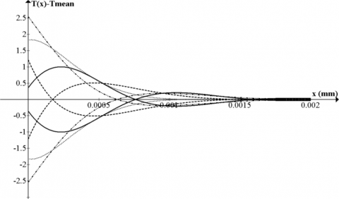
Some temperature profiles are plotted in Figure 7.
Figure 8. Temperature oscillations in the wall (they are only noticeable near the inside surface)
This paper has analyzed pro and contra of pulsejet propulsion focusing on valved pulsejets. In particular, after presenting the nature of the thermodynamic cycle, it produces a detailed analysis of the limits of this propulsion system that couples very low cost with a low efficiency and life cycle.
In particular, the analysis of the Lenoir cycle, together with the technical analysis of the problems connected with the faults of the Reed valve allows defining possible strategies for improving it. Actually, a revolutionary architecture with the aim of improving the life and the efficiency of the system is under study. This architecture, which cannot be disclosed because it is under pre-patenting analysis, will improve the system by introducing a preliminary compression and by using a different architecture for the valves.
This paper has determined the main thermodynamic parameters of a pulsejet and has exploited the possibility of cooling it both for increasing the duration of the traditional Reeds valves and for allowing the adoption of different and more robust valves.
The satisfactory results obtained allow determining the main parameters for the design of an effective cooling system and allow verifying its compatibility with the considered pulsejet size.
|
Q |
Heat, J |
|
|
T |
Temperature, K |
|
|
U |
Overall heat transfer coeff. (including radiation), W/m-2·K-1 |
|
|
V |
Volume, m3 |
|
|
W |
Work, J. |
|
|
cp |
Specific heat at constant pressure, J kg-1K-1 |
|
|
cv |
Specific heat at constant volume, J kg-1K-1 |
|
|
h |
Convection coefficient, W/m-2·K-1 |
|
|
k |
Thermal conductivity, W/ m-1·K-1 |
|
|
p |
Pressure, Pa |
|
|
q |
Heat for unitary surface, J/m-2 |
|
|
$\dot{q}$ |
Heat flux, J s-1 m-2 |
|
|
t |
Time, s |
|
|
x |
Wall Thickness, mm |
|
|
xc |
Penetration, mm |
|
|
R |
Universal gas constant [8.31446 J K−1 mol−1] |
|
|
Greek symbols |
|
|
|
$\alpha$ |
Positive constant of heat equation |
|
|
$\gamma$ |
heat capacity ratio |
|
|
$\tau$ |
Period [s] |
|
|
Subscripts |
|
|
|
0 |
initial |
|
|
1 |
final |
|
|
g |
gas |
|
|
w |
water |
|
Appendix
Appendix 1 is dedicated to explain in detail the main calculation method used to verify performances of the Lenoir cycle.
A1.1 Constant volume heat addition (1-2)
The heat addition phase (combustion) of a Lenoir cycle is a isochoric (constant volume) transformation. In the ideal gas version of the traditional Lenoir cycle, the first stage (1-2) involves the addition of heat in a constant volume manner:
$Q_{12}=m \cdot c_{v} \cdot\left(T_{2}-T_{1}\right)$(1)
and from the definition of constant volume specific heats for an ideal gas:
$c_{v}=\frac{R}{\gamma-1}$(2)
There is no work during the process because the volume is held constant:
$W_{12}=\int_{1}^{2} p \cdot d V=0$(3)
The pressure after the heat addition can be calculated from the ideal gas law:
$p_{2} \cdot V_{2}=R \cdot T_{2}$(4)
A1.2 Isentropic expansion (2-3)
The second stage involves a reversible adiabatic expansion (in the ideal case) or an isentropic expansion of the fluid back to the original pressure. For an isentropic process the second law of thermodynamics can be expressed by the following expression:
$\frac{T_{2}}{T_{3}}=\left(\frac{p_{2}}{p_{3}}\right)^{\frac{\gamma-1}{\gamma}}=\left(\frac{V_{3}}{V_{2}}\right)^{\gamma-1}$(5)
where p3 = p1 for this specific cycle. The first law of thermodynamics results in the following for this expansion process:
$W_{23}=\int_{2}^{3} p \cdot d V$(6)
because for an adiabatic process: Q23 = 0.
A1.3 Constant pressure heat rejection (3-1)
The final stage (3-1) involves a constant pressure heat rejection back to the original state and according to the first law of thermodynamics it can be described by
$Q_{31}-W_{31}=U_{1}-U_{3}$(7)
The definition of work assumes the following expression:
$W_{31}=\int_{3}^{1} p \cdot d v=p_{1} \cdot\left(V_{1}-V_{3}\right)$(8)
And the amount of heat rejected during this process is:
$\begin{aligned} Q_{31} &=\left(U_{1}+p \cdot V_{1}\right)-\left(U_{3}+p \cdot V_{3}\right) \\ &=H_{1}-H_{3}=m \cdot c_{p}\left(T_{1}-T_{3}\right) \end{aligned}$(9)
where
$c_{p}=\frac{\gamma \cdot R}{\gamma-1}$(10)
A1.4 Efficiency
The overall efficiency of the cycle is determined by the total work over the heat input,
$\eta_{t o t}=\frac{W_{23}+W_{31}}{Q_{12}}=\frac{\int_{2}^{3} p \cdot d V+p_{1} \cdot\left(V_{1}-V_{3}\right)}{m \cdot c_{v} \cdot\left(T_{2}-T_{1}\right)}$(11)
Note that we gain work during the expansion process but lose some during the heat rejection process.
[1] T. Geng, M. A. Schoen, A. V. Kuznetsov and W. L. Roberts, “Combined Numerical and Experimental Investigation of a 15-cm Valveless Pulsejet,” Flow, Turbulence and Combustion, vol. 78, no. 1, pp. 17–33. DOI: 10.1007/s10494-006-9032-8.
[2] K. Honecke, “Jet engines: Fundamentals of theory, design and operation,” Shrewsbury Airlife, pp. 36-41, 1997. ISBN-13: 978-1853108341.
[3] J. B. Heywood, Internal Combustion Engine Fundamentals, McGraw-Hill, New York, pp. 161-193, 1988. ISBN: 978-0070286375.
[4] A. Shavit and C. Gutfinger, Thermodynamics from Concepts to Applications, Second edition, New York: CRC Press, Taylor&Francis Group, pp. 290-312, 2009. ISBN: 978-1-4200-7368-3.
[5] W. H. Heiser, and D.T. Pratt, “Thermodynamic Cycle Analysis of Pulse Detonation Engines,” AIAA Journal of Propulsion and Power, vol. 18, no. 1, pp. 68-76, 2002. DOI: 10.2514/2.5899.
[6] L. B. Edelman, “The pulsating jet engine. Its evolution and future prospects,” SAE Quarterly Transactions, 1, pp. 204-216, 1947.
[7] F. H. Reynst, Pulsating Combustion, Pergamom Press, 1961.
[8] J. G. O’Brien, “The Pulsejet engine a review of its development potential,” Naval Postgraduate School, Monterey, CA, USA, pp. 12-34, 1973.
[9] VV. AA., Jane’s Fighting Aircraft of World War II, London, Studio Editions Ltd, 1989. ISBN 0-517-67964-7.
[10] B. Gunston, World Encyclopedia of Aero Engines, Cambridge, England. Patrick Stephens Limited, 1989. ISBN 1-85260-163-9.
[11] S. Zaloga, V-1 Flying Bomb 1942–52, Oxford, UK: Osprey Publishing, 2005. ISBN 978-1-84176-791-8.
[12] A. Mohammadi, M. Yaghoubi and M. Rashidi, “Analysis of local convective heat transfer in a spark ignition engine,” International Communications in Heat and Mass Transfer, vol. 35, pp. 215–224, 2008.
[13] G. Przybyla, S. Postrzednik, and Z. Zmudka, “The heat transfer coefficient calculation in the ICE cylinder based on ice pressure data,” Journal of Powertrain and Transport, vol. 20, no. 4, 2013.
[14] M. Sandford and L. Postlemthwaite, “Engine coolant flow simulation-a correlation study,” SAE Technical Paper, 930068, 1993. DOI: 10.4271/930068.
[15] M. Moechel, “Computational fluid dynamic (CFD) analysis of a six cylinder diesel engine cooling system with experimental correlations,” SAE Technical Paper 941081, 1994. DOI: 10.4271/941081.
[16] J. A. Roux, “Parametric cycle analysis of an ideal pulse detonation engine”, Journal of Thermophysics and Heat Transfer, vol. 29, no. 4, pp. 671-677, 2015. DOI: 10.2514/1.T4515.
[17] E. Wintenberger and J. E. Shepherd. “Thermodynamic cycle analysis for propagating detonations”, Journal of Propulsion and Power, vol. 22, no. 3, pp. 694-698, 2006. DOI: 10.2514/1.12775.
[18] E. Wintenberger, “Application of steady and unsteady detonation waves to propulsion,” M.S. Thesis, California Institute for Technology, pp. 23-30, 2004.
[19] J. G. O’Brien, “The Pulsejet engine a review of its development potential,” Naval Postgraduate School, Monterey, CA, USA, pp. 42-45, 1973.
[20] S. R. Chaurasia, R. Gupta and R. M. Sarviya, “Performance analysis of a Pulsejet engine,” International Journal of Engineering Research and Applications (IJERA), vol. 3, no. 4, pp. 605-609, 2013. ISSN: 2248-9622.
[21] P. Torda, et al., “Compressible flow through reed valves for pulse jet engines. 1. Hinged reed valves,” Technical Report No. 9, Project 9, 1948.
[22] K. Gaiser, D. Paxson and J. T’ien, “improved design of a self-actuated valve for pressure gain pulsejet combustors,” Internal report, Case Western Reserve University, 2010.
[23] A. Dumas and M. Trancossi, “A mathematical based design methodology for crossflow heat exchangers,” ASME 2009 International Mechanical Engineering Congress and Exposition (IMECE2009), Heat Transfer, Fluid Flows, and Thermal Systems, Parts A, B and C, vol. 9, Paper no. IMECE 43826, pp. 1159-1165, 2009. DOI: 10.1115/IMECE2009-43826.
[24] Dumas, A. and Trancossi, M., “Design of exchangers based on heat pipes for hot exhaust thermal flux, with the capability of thermal shocks absorption and low level energy recovery,” SAE Technical Paper 2009-01-3074, 2009. DOI: 10.4271/2009-01-3074.