OPEN ACCESS
In the lubrication analysis of piston ring-cylinder liner components for a diesel engine, it is usually assumed that the oil is Newton fluid. But in practice, the lubricant is not always in line with the law of viscosity, that is to say that the lubricant can characterize some non-Newtonian effect. In this paper, a power law fluid was taken as an example to establish the non-Newtonian liquid lubrication model of piston ring-cylinder liner components for a diesel engine. The model was solved by a MATLAB program simultaneously with the load equation. It was found by the results that when considering the non-Newtonian effect of lubricating oil, oil film pressure was different when the power law coefficient was different, but the distribution and the change trend of the oil film pressure was similar; and the highest oil film pressure appeared at a similar position .However, the value of the oil film pressure increased with the increase of the power law coefficient, that is, the greater the power law coefficient, the greater was the oil film bearing capacity. The power law coefficient had little effect on the maximum oil film pressure.
Diesel engine, Lubrication, Piston ring-cylinder liner components, Non-Newtonian effect.
Study of the lubrication of piston ring-cylinder liner components for diesel engines has been a hot topic for scientific researchers. Since the theory of friction and lubrication has been established, there has been no discontinuity in the study of the friction pair. In recent years, many results have been achieved. For example, Harigaya [1], Hamatake [2], Froelund, K [3], Ejakov [4], Hamatake, Toshiro [5], Toshiro and Y [6] Harigaya have studied the effects of lubricant viscosity on the film thickness and friction force of piston ring-cylinder liner components. TIAN [7-8] and the research impact of the dynamics of piston and piston ring set on the effect of friction and lubrication. Shayler [9], Felter [10], Livanos [11], Chong [12], Smith [13], Avan [14] have obtained some research findings on the friction pair of cylinder liner and piston ring. KONG LingJia [15], et al. have taken the influence of air leakage from a piston ring to the lubrication of the piston ring into consideration; LIU Kun [16], etc. have adopted a two-dimensional Reynolds equation in the calculation of piston ring lubrication and taken circumferential non-uniformity of a piston ring into account; ZHANG Yong [17], et al. have analyzed lubrication by a two-dimensional Reynolds equation; WANG Wei, LIU Kun [18], et al. have carried out research on the lubrication of cylinder sleeve and piston ring in the presence of liquid-solid lubricant; YE Xiaoming [19], et al. have studied the lubricating properties of a non-circular piston ring of cylinder sleeve; ZHOU Long, BAI Minli [20], et al. have adopted piston ring lubrication and thermal load effect for their solution and taken the heat transfer problems of a lubricant in the process of lubrication into account. DAI Xudong [21] has performed coupling analysis on the tribological and dynamic behavior of a cylinder sleeve and piston system.
Usually in the cylinder sleeve and piston ring lubrication analysis and calculation model, the lubricant was assumed to be Newtonian fluid. But the reality was that lubricants did not always conform to the Newton law of viscosity, which meant lubricants would reflect some other non-Newtonian effects. In addition, in order to improve the viscosity-temperature characteristics of the lubricant and reduce the chances of changing viscosity with temperature from time to time, some high polymer additives would often be added to the lubricants, leading to non-Newtonian effects such as shear thinning and visco-elastic effects. Charles [22], et al. have carried out research on the rheological properties of lubricants of a cylinder sleeve and piston ring friction pair. It showed that the friction coefficient was changed with the increase of shear rate and contact state was shifted to non-Newtonian fluid. Others have also proved that lubricants normally had the nature of shear thinning. The power law index was typically 0.9. It assumed that the lubrication calculation model of Newtonian fluid had failed and that it was necessary to establish a new calculation model to study the impact of non-Newtonian effects on lubricating properties. This paper has taken power law fluid as an example to set up a lubrication calculation model of the cylinder sleeve and piston ring friction pair, for the purpose of lubrication analysis.
2.1 Establishment of Power Law Fluid Lubrication Model
Constitutive equation of power law fluid can be written as [23]:
$\eta=m I^{\left(n_{1}-1\right) / 2}$(1)
In which, $\eta$ was the viscosity, $m$ was the consistency coefficient which was a material constant, $I$ was the second invariant of strain rate tensor, $I=\left(\frac{\partial u}{\partial y}\right)^{2}+\left(\frac{\partial w}{\partial y}\right)^{2} n_{1}$ was the power law index. As $n_{1}<1$, the lubricant’s shear was thinned. As$n_{1}=1$, the lubricant was Newtonian fluid. As $n_{1}>1$, the lubricant’s shear was thickened.
Ref. [24] has ignored the fact that the density changed with pressure and deduced an average Reynolds equation of power law fluid.
Supposed that the direction of $x$ and $z$ were used as fluid motion direction and the direction of $\mathcal{Y}$ was the direction of the film thickness; according to control equations of incompressible fluid as follows:
$\frac{\partial}{\partial y}\left(\eta \frac{\partial u}{\partial y}\right)=\frac{\partial p}{\partial x}$(2)
$\frac{\partial}{\partial y}\left(\eta \frac{\partial w}{\partial y}\right)=\frac{\partial p}{\partial z}$(3)
$\frac{\partial p}{\partial y}=0$(4)
$\frac{\partial u}{\partial x}+\frac{\partial v}{\partial y}+\frac{\partial w}{\partial z}=0$(5)
An average Reynolds equation of power law fluid in the form of:
$\frac{\partial}{\partial x}\left(\phi_{x} \frac{h^{2+n_{1}}}{n_{1}} \frac{\partial \overline{p}}{\partial x}\right)+\frac{\partial}{\partial z}\left(\phi_{z} h^{2+n_{1}} \frac{\partial \overline{p}}{\partial z}\right)$$=12 m U^{n_{1}-1}\left[\phi_{c} \frac{U}{2} \frac{\partial h}{\partial x}-\sigma \frac{U}{2} \frac{\partial \phi_{s}}{\partial x}+\phi_{c} \frac{\partial h}{\partial t}\right]$(6)
In the formula, $\varphi_{x}$represents pressure flow factor at x direction. $\varphi_{y}$represents pressure flow factor at y direction. $\overline{p}$ represents average oil film pressure among friction pairs. $\overline{h}_{T}$ is actual average of oil film thickness. $\varphi_{S}$ represents shear flow factor. With regard to all parameters in the average Reynolds equation, pressure flow factor $\varphi_{x}$ and $\varphi_{y}$ are the ratios of the average pressure flow of lubricants flowing through an uneven surface to that of lubricants flowing through a smooth surface. The ratio of obtained value to film thickness is related to the asperity length and width of an uneven surface. Please see ref. [25] for the obtained value.
If this is applied to a piston ring and cylinder sleeve lubrication system, assuming that the oil film is circumferentially and uniformly distributed along the piston ring and the cylinder sleeve remains static, but only the piston ring moves. It can be written in the form of following formula:
$\frac{\partial}{\partial x}\left(\phi_{x} \frac{h^{2+n_{1}}}{n_{1}} \frac{\partial \overline{p}}{\partial x}\right)$$=6 m u^{n_{1}} \phi_{c} \frac{\partial h}{\partial x}+6 m \sigma u^{n_{1}} \frac{\partial \phi_{S}}{\partial x}$$+12 m\left(\frac{u}{2}\right)^{n_{1}-1} \phi_{c} \frac{\partial h}{\partial t}$(7)
Then, successive over-relaxation method is used for the solution and the Reynolds boundary conditions are chosen.
2.2 Boundary conditions of Reynolds equation
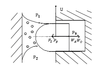
On the problem of solving the Reynolds equation, a series of boundary conditions were put forward, in which the Sommerfeld boundary conditions, the semi-Sommerfeld boundary conditions and the Reynolds boundary conditions are well-known, as shown in figure 1.
The Reynolds boundary conditions of cavitation can be expressed as:
$\left\{\begin{array}{ll}{P=P_{1} ;} & {\left(\mathrm{x}=x_{1}\right)} \\ {P=P_{2}, \frac{\mathrm{d} P}{d x}=0 ;} & {\left(\mathrm{x}=x_{2}\right)}\end{array}\right.$
In solving the Reynolds equation to solve the lubrication analysis in this paper, the Reynolds boundary conditions without cavitation are used.
Figure 1. Reynolds equation’s boundary conditions
3.1 Radial force analysis of piston ring
The radial force of the piston ring in the lubrication process is shown in Figure 2.
The radial force balance equation of piston ring body in the process of lubrication is as shown:
$F_{Z}+F_{E}=W_{O}+W_{A}$(8)
Among them, $F_{z}$ and $F_{E}$ represent gas tension and elastic force of piston ring,. The gas tension $F_{z}$ depends on the values of $p_{1}, p_{2}$ and ring body back pressure$p_{B}$.The value of $p_{B}$ is $p_{1}$ or $p_{2}$, subject to axial force analysis. $W_{A}$ and $W_{o}$ respectively represent asperity-carrying capacity force and oil film carrying capacity force. $p_{1}$ and $p_{2}$ are the upper and lower cavity pressure of the position where the piston ring is arranged and obtained through calculation of air leakage.
Figure 2. Radial force diagram of piston ring lubrication
3.2 Oil film carrying capacity
The oil film carrying capacity is
$W_{o}=\int_{x_{i}}^{x_{2}} \overline{p} d x$(9)
wherein,$x_{1}$ and $x_{2}$ are the starting and ending positions of the oil film. The Reynolds equation is solved based on boundary conditions. $W_{A}$ is obtained through the Greenwood-Trip roughness contact model formula [25].
A simultaneous solution method was used for the radial load balance equation and average Reynolds equation to obtain lubrication analysis data such as the minimum oil film thickness and minimum oil film pressure.
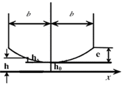
3.3 Barrel piston ring structure parameter
Assuming that the piston ring is a barrel ring, the structural parameters are shown in Figure 3.
Figure 3. Barrel piston ring structure parameters
The cylinder sleeve and piston ring friction pair of an inline six-cylinder diesel engine were taken as research object to prepare the MATLAB program and analyze lubrication. The piston ring of the diesel engine consisted of two gas rings and one oil ring. In this paper, the first gas ring was adopted for lubrication analysis. Main parameters required by lubrication calculation as shown in Table 1.
Table 1. Main parameters required by lubrication calculation
|
Calculation Parameters |
Numerical Value |
Unit |
|
Rotate Speed |
2200 |
R/min |
|
Roughness Variance of Cylinder Sleeve |
1.5×10⁻⁶ |
m |
|
Roughness Variance of Piston Ring |
1.5×10⁻⁶ |
m |
|
Height of Barrel Surface of Piston Ring |
5.0×10⁻⁶ |
m |
|
Elastic Force of Piston Ring |
556 |
N/m |
|
Temperature of Engine Oil |
80 |
℃ |
|
Height of Piston Ring |
3.5×10⁻³ |
m |
|
Lubricant Density(100℃)(Kg/m^3) |
890 |
kg/m3 |
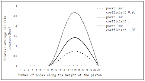
Suppose that the ratio between the minimum film thicknesses of the piston ring and the cylinder sleeve is 4, the friction pair falls just in the mixed lubrication area. Suppose that environmental pressures at both ends of oil film are a standard atmospheric pressure and relative pressure is used for the calculation; that is, assuming that the environmental pressures at both ends of the oil film is 0, the consistency coefficient m is equal to 0.038Pa.s. The velocity is set as a fixed value. The fact that the consistency coefficient varies with pressure is ignored. The oil film pressure is examined as the power law coefficient n1 is equal to 0.95, 1 and 1.05. The calculation results are shown in Figure 4. These show that the oil film pressure is mainly located at the right convergence zone. When the power law coefficient is different, pressure is distributed in the same shape; that was, the maximum oil film pressure appears in the same location and changes in the same way. However, the numerical value of the oil film pressure increases with the increase of the power law coefficient, namely, the larger the power law coefficient, the stronger the oil film carrying capacity. The reason is that the larger the power law coefficient, the stronger the shear thickening ability of the lubricant and thus the stronger the oil film carrying capacity.
Figure 4. Average oil film pressure of power law fluid with same oil film thickness
In this paper, a power law fluid was taken as an example to establish the non-Newtonian liquid lubrication model of piston ring-cylinder liner components for a diesel engine.
(1) When considering the non-Newtonian effect of lubricating oil, the oil film pressure was different while the power law coefficient was different, but the distribution and the change trend of the oil film pressure were similar.
(2) When the power law coefficient was different, the highest oil film pressure appeared at a similar position .However, the value of the oil film pressure increased with the increase of the power law coefficient, that is, the greater the power law coefficient, the greater was the oil film bearing capacity.
|
$\eta$ |
Viscosity(㎡/s) |
|
$m$ |
Consistency coefficient (Pa.Sn) |
|
$I$ |
Second invariant of strain rate tensor |
|
$\varphi_{x}$ |
pressure flow factor at x direction |
|
$\varphi_{y}$ |
pressure flow factor at y direction |
|
$\overline{p}$ |
average oil film pressure among friction pairs (Pa) |
|
$\overline{h}_{T}$ |
actual average oil film thickness(m) |
|
$\varphi_{S}$ |
shear flow factor |
|
$F_{Z}$ |
gas tension(N) |
|
$F_{E}$ |
elastic force of piston ring(N) |
|
$p_{B}$ |
ring body back pressure (Pa) |
|
$p_{1}$ |
upper cavity pressure of the position where the piston ring is arranged (Pa) |
|
$p_{2}$ |
lower cavity pressure of the position where the piston ring is arranged (Pa) |
[1] Y. Harigaya, M. Ichinose and M. Suzuki, “Effect of temperature on the lubrication characteristics between the piston ring and the cylinder liner of internal combustion engine,” ASME, 19 Internal Combustion Engine Division (Publication) ICE, vol. 27, no. 2, pp.17-24, 1996.
[2] T. Hamatake, Y. Wakuri, M. Soejima and et al., “Effects of lubricant viscosity on the mixed lubrication of a piston ring pack in an internal combustion engine,” in Proceedings of the International Tribology Conference, Nagasaki 2000, pp. 2023-2028.
[3] K. Froelund, J. Schramm and T. Tian, “Analysis of the piston ring/liner oil film development during warm-up for an SI-Engine,” Journal of Engineering for Gas Turbines and Power, vol. 123, no.1, pp. 109-116, 2001, DOI: 10.1115/1.1341206.
[4] Ejakov and A. Mikhail, “Modeling of axial and circumferential ring pack lubrication,” ASME, Internal Combustion Engine Division, ICE, vol. 37, no. 3, pp. 77-88, 2001.
[5] T. Hamatake, Y. Wakuri, M. Soejima and et al, “Effects of lubricant viscosity on the mixed lubrication of a piston ring pack in an internal combustion engine,” Lubrication Science, vol. 15, no. 2, pp. 101-117, 2003.
[6] Y. Harigaya, M. Suzuki and M. Takiguchi, “Analysis of oil film thickness on a piston ring of diesel engine: Effect of oil film temperature,” Journal of Engineering for Gas Turbines and Power, vol. 125, no. 3, pp. 596-603, 2003.
[7] T. Tian, “Dynamic behaviours of piston rings and their practical impact. Part 1: Ring flutter and ring collapse and their effects on gas flow and oil transport,” Proceedings of the Institution of Mechanical Engineers, Part J: Journal of Engineering Tribology, vol. 216, no. 4, pp. 209-227, 2002. DOI: 10.1243/135065002760199961.
[8] T. Tian, “Dynamic behaviours of piston rings and their practical impact. Part 2: Oil transport, friction and wear of ring/liner interface and the effects of piston and ring dynamics,” Proceedings of the Institution of Mechanical Engineers, Part J: Journal of Engineering Tribology, vol. 26, no. 4, pp. 229-247, 2002. DOI: 10.1243/135065002760199970.
[9] P.J. Shayler, D.K.W. Leong, I.G. Pegg and M. Murphy, “Investigations of piston ring pack and skirt contributions to motored engine friction,” SAE International Journal of Engines, vol. 1, no. 1, pp. 723-734, 2009. DOI: 10.4271/2008-01-1046.
[10] C.L. Felter, A. Vlund, T. Imran and P. Klit, “Development of a model capable of predicting the performance of piston ring-cylinder liner-like tribological interfaces,” Proceedings of the Institution of Mechanical Engineers, Part J: Journal of Engineering Tribology, vol. 224, no. 9, pp. 877-883, 2010. DOI: 10.1243/13506501JET720.
[11] G. Livanos, “Development of a simplified instantaneous friction model of the piston-crank-slider mechanism of internal combustion engines,” SAE International Journal of Engines, vol. 4, no. 1, pp. 581-596, 2011. DOI: 10.4271/2011-01-0612.
[12] W.W.F. Chong, Teodorescu M., Vaughan, N.D, “Cavitation induced starvation for piston-ring/liner tribological conjunction,” Tribology International, vol. 44, no. 4, pp. 483-497, 2011. DOI: 10.1016/j.triboint.2010.12.008.
[13] E. H. Smith, “Optimising the design of a piston-ring pack using DoE methods,” Tribology International, vol. 44, no. 1, pp. 29-41, 2011. DOI: 10.1016/j.triboint.2010.09.002.
[14] A. E. Yusuf, M. Robin and D.J. Rob, “Frictional characteristics of ultrasonically measured lubricant films in a simulated piston ring liner contact,” in SAE 2011 World Congress and Exhibition, SAE 2011 World Congress and Exhibition, 2011. DOI: 10.4271/2011-01-1400.
[15] L. J. Kong and Y. B. Xie, “Calculation of blow-by gas, lubricaton, friction and wear in cylinder liner-piston ring tribo-systems,” Transactions of CSICE, vol. 10, no. 3, pp. 267-274, 1992.
[16] K. Liu, C. L. Gui and Y. B. Xie, “Study of circumferential non-uniformity of piston ring lubrication,” Transactions of CSICE, vol. 15, no. 3, pp. 281-289,1997.
[17] Y. Zhang, M. J. Luo, G. H. Chen and et al., “Two dimensional analysis of lubrication for piston ring-cylinder liner pair,” Chinese Journal of Mechanical Engineering, vol. 35, no. 6, pp. 21-24, 1999.
[18] W. Wang, K. Liu, M. H. Jiao and X. J. Liu, “Investigation of liquid-solid two-phase lubrication for piston ring-cylinder liner,” Transactions of CSICE, vol. 23, no. 2, pp. 176-181, 2005.
[19] X. M. Ye, Y. K. Jiang and X. L. Hao, “Study on the effects of cylinder liner radial deformation on elastohydrodynamic lubrication performance of piston ring,” Vehicle Engine, vol. 168, no. 2, pp. 22-25, 2007.
[20] L. Zhou, M. L. Bai and J. Z Lv, “Numerical simulation into influence of structural parameters on lubrication and friction performance of piston ring-liner,” Transactions of CSICE, vol. 26, no. l, pp. 69-75,2008.
[21] X. D. Dai, S. X. Zhao, X. Y. Yuan and Y. B. Xie, “Study on coupling system dynamical behavior to hydrodynamic lubrication in internal combustion engine,” Journal of Xi’an Jiaotong University, vol. 37, no. 7, pp. 56-59, 2003.
[22] P. Charles, S. Mezghani, I. Demirci, H. Zahouani and M. Mansori, “The effect of groove texture patterns on piston-ring pack friction,” Precision Engineering, vol. 36, no. 2, pp. 210-217, 2012. DOI: 10.1016/j.precisioneng.2011.09.008.
[23] B. G. Wang, H. D. Jiang and H. Y. Ma, Engineering Fluid Mechanics, Beijing: Science Press, 2011.
[24] X. K. Chen and Z. G. Qiu, “Application of the average flow model for power-law fluid to dynamically loaded rough,” Journal of Fudan University (Natural Science), vol. 34, no. 6, pp. 671-677, 1995.
[25] N. Patir and H. Cheng, “An average flow model for determining effects of three-dimensional roughness on partial hydrodynamic lubrication,” Trans. ASME J. Vib. Acoust., vol. 100, no. 1, pp. 12–17, 1978.