OPEN ACCESS
Forced convection, Heat transfer enhancement, Solar air preheater, Bluff, Cylinders, Swirl flow.
Energy efficiency and energy saving are one of the major scientists concern in the last decade because of the increase in energy global demand and consumption as result of economic development and population growth. Solar energy, radiant light and heat from the sun, has been harnessed by humans since ancient times using a range of ever-evolving technologies. Before 1970, some research and development was carried out in a few countries to exploit solar energy more efficiently, but most of this work remained mainly theoretical and academic. After the dramatic rise in oil prices in the 1970s, several countries began to formulate extensive research and development programs to exploit solar energy. Solar air heater is an effective device to harness solar energy and used for heating purposes i.e., drying of crops, seasoning of timber, space heating etc. A simple solar air heater consists of an absorber plate to capture solar radiation and transfers this solar (thermal) energy to air via conduction heat transfer. This heated air is then ducted to the building space or to the process area where the heated air is used for space heating or process heating needs.
Various investigators have studied different types of roughness geometries and their arrangements. Jaramillo et al. [1] studied the effect on enhancement of heat transfer in a parabolic solar collector and numerical result is having good agreement with experimental data. Yao et al. [2] studied numerically about the performance evaluation of all-glass evacuated tube solar water heater with twist tape inserts and shows that the twist tape inserts helps heat transfer at comparatively high temperature and is not conducive to heat transfer at relatively low temperature. Ghadirijafarbeigloo et al. [3] worked with louvered twisted-tape in a receiver tube of solar parabolic trough concentrator. Jaisankar [4] reported experimentally on heat transfer and friction factor characteristics of forced circulation solar water heater system fitted with helical twisted tapes and also developed correlations for Nusselt number and friction factor with various twist ratios. Raja Sekhar et al. [5] worked with Al2O3 nano-fluids and twisted tapes in a pipe for solar thermal heater.
Figure 1. The geometry of swirls generators (cylinders)
Saha and co-workers [6–10] have studied experimentally laminar flow through square and rectangular ducts having twisted tapes types vortex generator with oblique teeth, axial corrugations, transverse ribs and wire coil inserts. Hasim et al. [11] and Zimparov et al. [12] have contributed on combined heat transfer enhancement techniques. Saha et al. [13] has presented has worked on axial corrugations and twisted-tape having centre clearance and obtained promising results. Adewumi et al. [14] studied numerical to investigate the best geometric configuration that maximises heat transfer from the heated base by allowing both the length of the solid substrate and the microchannel heat sink freedom to morph. Zhang et al. [15 numerically investigate high temperature molten salt flow and heat transfer characteristics in paddle heat exchanger by using CFD code.
It has been observed from the literature review that the number of bluff cylinders has not been studied in the past. The geometry of bluff cylinders is shown in Figure 1. The spiral fluid flow due to spring generated swirl flow is likely to give larger swirl intensity and vortex in the flow. Also they may enhance fluid mixing with increased heat and momentum diffusion. This may increase heat transfer even if it may also give increased pressure drop. In this paper, therefore, the turbulent flow experimental heat transfer and pressure drop results of effect of number of bluff cylinder in circular ducts are presented.
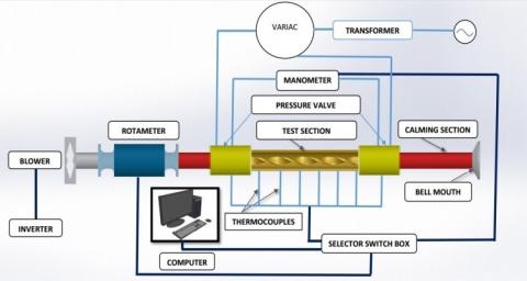
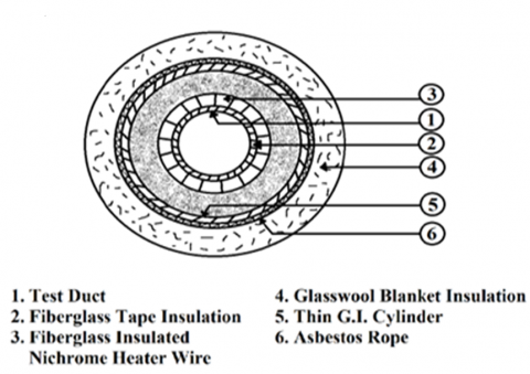
An experimental set-up has been designed and fabricated to investigate the effect of bluff cylinders on heat transfer and fluid flow characteristics in circular duct. The heat transfer and pressure drop measurements were taken in an 18 mm ID, 20 mm OD and 2 m long circular brass duct. Figure 2 shows the experimental rig. At the beginning nichrome heater was switched on and allowed to heat the test section. After few minutes the 7.0 KW blower was switched on. The electric power was adjusted with the help of variac. The flow rate of air was measured by rotameter and it’s controlled by flow-control valve. First the variations in wall temperatures at all locations were observed until constant values were attained at all the seven locations. At the steady state condition thermocouple readings were monitored with the help of the selector switch and then recorded. The manometer readings were observed and taken from the U-tube manometers. The air flow rate was changed with the help of the flow control valve after each experimental run hence changed the Reynolds number. There was no direct contact of the nichrome heater wire with the duct wall. There was layer of insulations on the duct wall as shown in Figure 3.
Experimental uncertainty was determined by the method of Saha et al. [16]. The maximum uncertainties of the non-dimensional parameters were found ±1.77% for velocity, ±4.5% for heat transfer rate, ±5.5% for Nusselt number, and ±2.36% for friction factor. The errors are shown in Table. 1.
Figure 2. Schematic diagram of the experimental facility
Figure 3. Different insulation layers on test section
Table 1. Uncertainties of major parameters
|
Sl. No. |
Name of variables |
Errors |
|
01 |
Flow velocity, v |
0.18% |
|
02 |
Voltage on the heater, V |
0.15% |
|
03 |
Electrical resistance, R |
0.33% |
|
04 |
Heat transfer coefficient, h |
1.19% |
|
05 |
Current on the heater, I |
0.23% |
|
06 |
Ambient temperature, Ta |
0.1% |
|
07 |
Electrical power on the heater, P |
0.17% |
|
08 |
Average temperature, T |
0.6% |
Considering the air flow (Pr = 0.7) in the channel with heat transfer, the mathematical model applied is composed of the conservation equations of mass, momentum and energy for incompressible flow in three dimensions.
The Reynolds number of air flow in the duct is calculated from,
$R e=\frac{\rho v D}{\mu}$(i)
Steady state values of the plate and air temperatures in the duct at various locations were used to determine the values of useful parameters, namely heat supplied to the air “Qu” and heat transfer coefficient “h” calculated as:
$Q_{u}=\dot{m} C_{p}\left(T_{a o}-T_{a i}\right)$(ii)
$h c=\frac{Q_{u}}{A_{p}\left(T_{p}-T_{f}\right)}$(iii)
The convective heat transfer coefficient is then used to obtain Nusselt number, Nu, as,
$N u=\frac{h D_{h}}{k}$(iv)
The friction factor is determined from the measured values of pressure drop (∆P), across the test section length.
$f=\frac{2(\Delta P) D_{h}}{4 \rho L V^{2}}$(v)
Or,
$\mathrm{f}=\frac{2(\Delta \mathrm{P}) \rho \mathrm{D}_{\mathrm{h}}}{4 \mathrm{L} \mathrm{G}^{2}}$(vi)
where $\mathrm{G}=\mathrm{m} / \mathrm{WH}$ is the mass velocity of air.
To evaluate the effect of heat transfer enhancement under given pumping power, the formula of performance evaluation criteria is employed by Yang et al. [17]
Efficiency$=\left[\frac{N u / N u_{o}}{\left(f / f_{0}\right) 0.33}\right]^{1}$(vii)
where Nu and Nu0 are Nusselt numbers for the enhanced tube and the smooth tube respectively, f and f0 are friction coefficients for enhanced tube and smooth tube respectively.
Verification of smooth duct
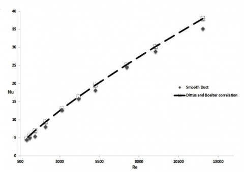
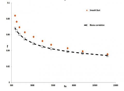
The experimental results on heat transfer and pressure drop characteristic in terms of Nusselt number and friction factor of the smooth duct are presented and validated with the correlations of Dittus–Boelter and Blasius [18]. From Figure 4 and Figure 5 one can see that the results from the smooth duct agree well with those from the standard correlations within ± 5% deviations for Nusselt number and ±7% for friction factor.
Dittus and Boelter correlation [16],
$N u=0.023 R e^{0.8} P r^{0.4}$(viii)
Blasius correlation [16],
$f=0.448 R e^{-0.275}$(ix)
Figure 4. Verification of Nusselt number for the plain tube
Heat transfer characteristics
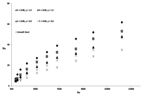
The heat transfer performance of bluff cylinders is presented in the form of Nusselt number. Variation of Nusselt numbers with Reynolds numbers for the bluff cylinders with different diameter ratio (h = d/D) and pitch ratio (y = p/D) and smooth duct are shown in Figure 6. Reynolds numbers is varied between 993 to 12,034. Nusselt number (Nu) considerably increases with increasing Reynolds number, reflecting the increase of convective heat transfer. d = 0.06, y = 1.5 has the highest Nusselt number and the base case has the lowest heat transfer. This implies that the heat transfer rate increases with decreasing pitch ratio and increasing diameter ratio. It could be attributed from Figure 6 that the bluff cylinders inserts caused vortex/swirl flow and pressure gradient being generated along radially. The boundary layer along the channel wall would becomes thinner with the increased of radial vortex. Furthermore, the vortex increases the flow turbulence, which led to even good convection heat transfer.
Figure 5. Verification of friction factor for the plain tube
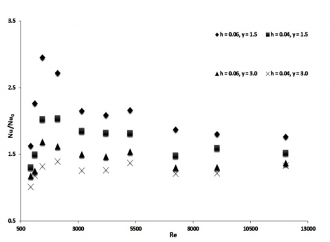
Figure 7 shows the relation of Nu/Nu0 with Reynolds number. It also compares the heat transfer in bluff cylinders in a duct with straight smooth duct. Compared to straight smooth duct, heat transfer enhancement is observed in bluff cylinders duct. All the value is greater than unity; this enhancement is due to secondary flow induced by the bluff cylinders, which promotes radial mixing of bulk flow with near-wall flow.
Figure 6. Variation of Nusselt number with Reynolds number for different diameter ratio and pitch ratio
Flow characteristics
Friction factor results are presented in Figure 8. The figure shows the relationship between the friction factor and Reynolds number at different pitch ratios and diameter ratios for all bluff cylinders duct and smooth duct. For all cases, friction factor conventionally decreases with the increasing Reynolds number.This is because the attributed to the use of bluff cylinders which led to a higher viscous loss near the tube wall regions caused by a stronger swirl flow or turbulence flow and long residence time in the duct.
From Figure 9 it is visible that both the f and f/f0 tend to decrease with the increase of Re, for all cases. Similar to the f trends, the f from the inserted bluff cylinders is considerably higher than that from the plain channel alone at a given Re.
Figure 7. Variation of Nu/Nu0 with Reynolds number for different diameter ratio and pitch ratio Flow characteristics
Figure 8. Variation of friction factor with Reynolds number for different diameter ratio and pitch ratio
Figure 9. Variation of f/f0 with Reynolds number for different diameter ratio and pitch ratio
Thermal Performance Characterises
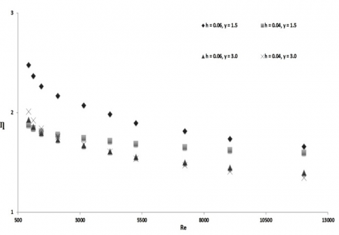
In Figure 10, the curve of the thermo-hydraulic performance parameter (Ƞ) is presented. The thermal performance is the ratio of the dimensionless Nusselt number and the dimensionless friction factor and this ratio shows the amount of the energy is saved. As it is common in heat transfer research and literature the thermal performance is shown in Figure 10. Results illustrate that the typical nature of efficiency with increasing Reynolds number and this show better performance of the duct with bluff cylinders. By doing the entire experimental investigation on bluff cylinders duct of different pitch ratio and diameter ratio it was found efficient from the energy point of view and enhancement efficiency was found to be greater than the unity. The enhancement efficiency above unity indicated that the effect of heat transfer enhancement due to the tabulators was more dominant than the effect of rising friction and vice versa.
Figure 10. Variation of thermal enhancement efficiency with Reynolds number for different diameter ratio and pitch ratio
The experimental friction factor and Nusselt number data for turbulent flow through a circular duct with circular bluff cylinders have been presented. The thermohydraulic performance has been evaluated. Bluff cylinders perform significantly better than the smooth pipe. The swirl flow is generated as fluid flowing through the smooth duct with circular bluff cylinders. Due to the presence of swirl flow, the convective heat transfer increases with increase of Reynolds number, however, the pressure drops also increase. Expecting that at higher Reynolds number the performance will be better.This research finding is useful in designing heat exchangers tubes.
The authors would like to gratefully acknowledge the MCKV Institute of Engineering (MCVIE) for their support in this research.
|
Ax |
cross sectional area of test section [m2] |
||||
|
Cp |
specific heat at constant pressure [J/(kg°C)] |
||||
|
D |
tube inside diameter [m] |
||||
|
d |
Roughness diameter [m] |
||||
|
f |
friction factor, dimensionless |
||||
|
h |
Diameter ratio, dimensionaless |
||||
|
hc |
convective heat transfer co-efficient [W/m2 °C] |
||||
|
hx |
local convective heat transfer co-efficient [W/m2 °C] |
||||
|
k |
thermal conductivity [W/m °C] |
||||
|
L |
tube length [m] |
||||
|
m˙ |
mass flow rate [kg/s] |
||||
|
ΔP |
pressure drop along axial length of tube [N/m2] |
||||
|
Pi |
inlet pressure [N/m2] |
||||
|
Pm |
blower power [W] |
||||
|
P(x) |
pressure at any axial location, x [N/m2] |
||||
|
Q |
heat transfer rate [W] |
||||
|
Ti |
inlet temperature [°C] |
||||
|
To |
outlet temperature [°C] |
||||
|
V |
mean velocity in the test section [m/s] |
||||
|
Vi |
mean velocity at inlet section [m/s] |
||||
|
W |
wetted perimeter [m] |
||||
|
y |
Pitch ratio |
||||
|
Dimensionless numbers |
|||||
|
Nu |
Nu |
||||
|
Pr |
Pr |
||||
|
Re |
Re |
||||
|
Subscripts |
|||||
|
b |
bulk |
||||
|
i |
inlet |
||||
|
o |
outlet |
||||
|
p |
tape inserts |
||||
|
s |
smooth |
||||
|
x |
Local |
||||
|
Greek Symbols |
|||||
|
µ |
fluid dynamic viscosity, kg/ms. |
||||
|
ρ |
density of the fluid, kg/m3 |
||||
|
α |
entrance angle of the tape |
||||
|
$\beta_{\mathrm{m}}$ |
average synergy angle $=\cos ^{-1}\left(\frac{\int|\overrightarrow{\mathrm{U}}||\vec{\nabla} \mathrm{T}| \cos \beta \mathrm{d} \mathrm{V}}{\int|\overrightarrow{\mathrm{U}}||\overrightarrow{\mathrm{P}} \mathrm{T}| \mathrm{d} \mathrm{V}}\right)$ |
||||
[1] Jaramillo, O. A., Borunda, M., Velazquez-Lucho, K. M. and Robles, M., “Parabolic trough solar collector for low enthalpy processes: An analysis of the efficiency enhancement by using twisted tape inserts,” Renewable Energy, vol. 93, pp. 125-141, 2016. DOI: 10.1016/j.renene.2016.02.046.
[2] Yao, K., Li, T., Tao, H., Wei, J. and Feng, K., “Performance evaluation of all-glass evacuated tube solar water heater with twist tape inserts using CFD,” Energy Procedia, vol. 70, pp. 332-339, 2015. DOI: 10.1016/j.egypro.2015.02.131.
[3] Ghadirijafarbeigloo, S., Zamzamian and A. H., Yaghoubi, M., “3-D numerical simulation of heat transfer and turbulent flow in a receiver tube of solar parabolic trough concentrator with louvered twisted-tape inserts,” Energy Procedia, vol. 49, pp. 373-380, 2014. DOI: 10.1016/j.egypro.2014.03.040.
[4] Jaisankar, S., Radhakrishnan, T. K. and Sheeba, K. N., “Experimental studies on heat transfer and friction factor characteristics of forced circulation solar water heater system fitted with helical twisted tapes,” Solar Energy, vol. 83, no. 11, pp. 1943-1952, 2009. DOI: 10.1016/j.solener.2009.07.006.
[5] Raja Sekhar, Y. Sharma, K. V. and Thundil Karupparaj, R., “Heat Transfer Enhancement with Al2O3 Nanofluids and Twisted Tapes in a Pipe for Solar Thermal Applications,” Procedia Engineering, vol. 64, pp. 1474-1484. 2013. DOI: 10.1016/j.proeng.2013.09.229.
[6] Saha, S. K. and Mallick, D. N., “Heat transfer and pressure drop characteristics of laminar flow in rectangular and square plain ducts and ducts with twisted tapes,” ASME J. Heat Transfer, vol. 127, no. 9, pp. 966–977, 2005.
[7] Pramanik, D. and Saha, S. K., “Thermohydraulics of laminar flow through rectangular and square ducts with transverse ribs and twisted tapes,” ASME J. Heat Transfer, vol. 128, no. 10, pp. 1070–1080, 2006.
[8] Saha, S. K., “Thermohydraulics of laminar flow through rectangular and square ducts with axial corrugation roughness and twisted tapes with oblique teeth,” ASME J. Heat Transfer, vol. 132, no. 8, pp. 081701(1–12), 2010.
[9] Pal, P. K. and Saha, S. K., “Thermal and friction characteristics of laminar flow through square and rectangular ducts with transverse ribs and twisted tapes with and without oblique teeth,” J. Enhanced Heat Transfer, vol. 17, no. 1, pp. 1–21, 2010.
[10] Saha, S. K., “Thermal and friction characteristics of laminar flow through rectangular and square ducts with transverse ribs and wire coil inserts,” Exp. Therm. Fluid Sci., 34, no. 1, pp. 63–72, 2010. DOI: 10.1016/j.expthermflusci.2009.09.003.
[11] Hasim, F., Yoshida, M. and Miyashita, H., “Compound heat transfer enhancement by a combination of a helically ribbed tube with twisted tape inserts,” J. Chem. Eng. Jpn., 35, no. 9, pp. 1116–1122, 2003.
[12] Zimparov, V. D., Penchev, P. J. and Bergles, A. E., “Performance characteristics of some ‘‘rough surfaces’’ with tube inserts for single-phase flow,” J. Enhanced Heat Transfer, vol. 13, no. 2, pp. 117–137,2006.
[13] Saha, S. K., Bhattacharyya, S. and Pal, P. K., “Thermohydraulics of laminar flow of viscous oil through a circular tube having integral axial rib roughness and fitted with center-cleared twisted-tape,” Exp. Therm. Fluid Sci. 41, 121-129, 2012. DOI: 10.1016/j.expthermflusci.2012.04.004.
[14] Adewumi, O. O., Ochende, T. B. and Mayer, J. P., “Constructal design of single microchannel heat sink with varying axial length and temperature-dependent fluid properties,” International Journal of Heat and Technology, vol. 34, no. 1, pp. s167–s172. DOI: 10.18280/ijht.34S122.
[15] Zhang, K., Du, J., Liu, X. and Zhang, H., “Molten salt flow and heat transfer in paddle heat exchangers,” International Journal of Heat and Technology, vol. 34, no. 1, pp. 43–50, 2016. DOI: 10.18280/ijht.34S106.
[16] Saha, S. K., Bhattacharyya, S. and Dayanidhi, G. L., “Enhancement of heat transfer of laminar flow of viscous oil through a circular tube having integral spiral rib roughness and fitted with helical screw-tape
inserts,” Heat Transfer Res., vol. 43, no. 2, pp. 207–227, 2012.
[17] Yang, L., Han, H., Li, Y. and Li, X., “A numerical study of the flow and heat transfer characteristics of outward convex corrugated tubes with twisted-tape insert,” ASME J. Heat Transfer, vol. 138, pp. 024501 (1– 8), 2016.
[18] Ozisik, M. N., Heat Transfer, New York: Mc-Graw-Hill, 1985.