OPEN ACCESS
In this paper, a new configuration of drop-shaped tube is proposed to improve the finned-tube thermo-flow performance. As the basic heat exchanger element of a Direct Air Cooled Condenser (DACC), the performance of finned tubes is very important to the optimal design of DACCs. Under turbine rated load (TRL) conditions and various frontal air velocities, the airside flow and heat transfer performance of single row flattened finned tubes and drop-shaped finned tubes are numerically investigated. The flow field, temperature field and thermo-flow characteristics are analyzed. Experimental verification and field coordination (synergy) analysis are carried out, with the simulation results agreeing well with experimental results. The performance of pressure drop, heat transfer coefficient and power consumption of these 4 Schemes are comprehensively compared and evaluated. When compared to the flattened finned tube the pressure drop of the drop-shaped Scheme 4 tube reduced by 5.9 % while the heat transfer coefficient reduced by 2.8 % at a frontal velocity of 1.8 m/s. Scheme 4 produces the best thermo-flow performance, especially at low air velocity, benefiting from a lower pressure drop and a moderate heat transfer coefficient.
Drop-shaped tube, Heat transfer enhancement, Numerical simulation, Single row finned tube.
During the last decade, the application and popularity of air-cooled condensers in power plants has been increasing rapidly throughout countries where water resources are in shortage [1]. In a direct air-cooled power generating unit, the ambient air replaces water as the cooling medium with obvious water conservation benefits. A Direct Air-Cooled Condenser (DACC) is composed of arrays of A-frame condenser cells, each fitted with an axial flow fan below. Ambient air is drawn in by fans to flow through the finned tube bundles, removing the emitted heat of the exhaust steam from the turbine. DACC heat exchangers usually use finned tubes to enhance heat transfer efficiency. The basic heat exchanger elements of an air-cooled condenser in power plants have experienced three design stages: multi-row circular tubes with annular fins, double-row elliptical tubes with rectangular fins and single-row wavy-finned flattened tubes. Of these, single-row finned tubes is the most popular. The thermo-flow performance of single-row finned tubes is very important to the optimal design and safe operation of DACCs and the efficiency of power plants. The shapes and configurations of tubes and fins directly affect the performance of air-cooled condensers. By now there are many different kinds of single row finned tubes such as wavy-finned flattened tubes, drop-shaped tubes [2], shaped tubes [3], vacuuming tubes [4] and finned partition walls [5] etc. The thermo-flow characteristics of finned tubes for many engineering applications have been thoroughly researched in the last few decades. Mon and Gross [6] investigated the effects of fin spacing on four-row annular finned tube bundles in staggered and in-line arrangements, finding that the boundary layer development and horseshoe vortices between the fins were substantially dependent on the fin spacing to height ratio and the Reynolds number. Ibrahim [7] investigated the thermo-fluid characteristics of finned elliptic tube bundles in crossflow with a reference to the circular tube bundle. PioroMatos et al. [8] performed a three-dimensional geometric optimization to maximize the total heat transfer rate for a bundle of finned tubes in staggered arrangements of circular and elliptic tubes, showing that the elliptical tube arrangement has a better overall performance and a lower cost than the traditional circular tube. Pioro I.L. [9] made a systematic literature search of the effect of simple flow geometry (rectangular, triangular, and dumb-bell shaped) on critical heat flux. Nemati H. [10] numerically studied efficiency of annular elliptical fin. Yan and Sheen [11] experimentally studied the pressure drop and heat transfer characteristics of the fin-and-tube heat exchangers with plate, wavy and louvered fin surfaces. The heat transfer coefficient and pressure drop were obtained for various frontal air velocities.
When the fluid flows across a circular tube, a large separation zone created by the boundary layer separation is developed at the rear of tube. In recent years, non-circular tubes with a stream-lined outer surface have attracted more and more attention for energy conservation. Drop-shaped tubes are attractive for high efficiency and energy conservation properties, whose cross-sectional profile is comprised of two circular arcs and their tangents. There are some experimental and numerical investigations into the heat transfer characteristics of new-type finned tubes. Nouri-Borujerdi and Lavasani [12], Horvat et al. [13] found that all non-circular tubes exhibit low flow resistance and high Nusselt numbers compared to circular tubes with the same circumferential length. Cheng [14] and Li [15] conducted experimental studies of heat transfer and flow resistance of a droplet-shaped tube, and concluded that the tested droplet-shaped tube had better heat transfer and lower flow resistance than those of a circular or an elliptical tube with equal circumference length. Liang [16] numerically studied the air flow field, the results show that the heat transfer performance is the best among those simulated types of tube. Li [17] experimentally investigated another drop-shaped tube and summarized that drop-shaped tubes have similar local Nu values as circular tubes before flow separation while the value was quite different after the separation point which correlated with the Re number.
From the literature reviewed above, it can be seen that the thermo-flow characteristics of drop-shaped tubes is obvious. No mention is reported as to the application of drop-shaped tubes applied to power plant condensers so far. Due to various engineering fields the characteristic parameters of drop-shaped tubes greatly vary. This paper proposes a new drop-shaped tube of easier production and lower flow resistance. The airside flow and heat transfer characteristics of single row finned tubes and the proposed drop-shaped finned tubes are numerically investigated. Experimental verification and field coordination analysis are carried out. Then the best scheme for a drop-shaped finned single row tube is determined.
2.1 Physical model
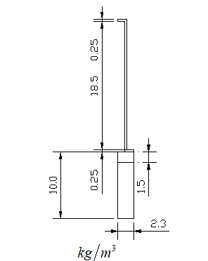
The flattened tube used currently and the proposed drop-shaped tubes are schematically shown in Figure.1. They are composed of base tubes and wavy fins. Air flows from bottom to top outside the finned tubes. For a proper comparison of the thermo-flow characteristics with the conventional flattened tube, three differently dimensioned tubes are proposed to apply to DACC condensers. Table 1 lists the geometric dimensions of the physical models, of which Scheme 1 is the conventional flattened tubes, and Schemes 2, 3, 4 are the proposed drop-shaped tubes. The thickness of base tubes is 1.5 mm, the fin pitch is 2.3 mm.
(a)Single row flattened tube
(b) Single row drop-shaped tube
Figure 1. Schematic of flattened and drop-shaped finned tubes
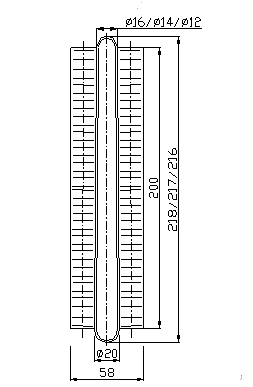
Table1. Dimensions of flat tubes and drop-shaped tubes
|
Scheme |
$k g / m^{3}$ (mm) |
Windward D (mm) |
Leeward D(mm) |
Fin$L \times H \times \delta$ (mm) |
|
1 |
219×1.5 |
19 |
19 |
190×19×0.25 |
|
2 |
218×1.5 |
20 |
16 |
200×19×0.25 |
|
3 |
217×1.5 |
20 |
14 |
200×19×0.25 |
|
4 |
216×1.5 |
20 |
12 |
200×19×0.25 |
2.2 Governing equations
As wet steam condensates in the base-tube, it releases latent heat. The heat from the condensation inside the tube is conducted to the outer surface and then convected to the flow-crossing air through the base tube and fins. Therefore the heat transfer of a drop-shaped finned tube is a coupled problem of air convection and solid thermal conductivity. Meanwhile some factors are ignored for model simplification, including thermal resistance, contact thermal resistance and heat radiation between the tube and fins, as well as the fouling thermal resistance. Generally the performance of ACC is evaluated under turbine rated load (TRL) conditions. The performance of single row tubes under TRL should be ascertained. Numerical simulations are made under TRL conditions. The TRL conditions in summer are: air pressure 1 atm standard, inlet air temperature 32 ℃, the characteristic temperature 50 ℃, air density 1.037$k g / m^{3}$, dynamic viscosity 1.96×10⁻⁵$k g /(m \cdot s)$. We assume that the three-dimensional steady flow in the model is laminar. The air Reynolds number varies between 196-509. The flow in the computational domain is considered as an incompressible fluid with constant physical properties. The air flow and heat transfer in the computational domain satisfy the following governing equations. The mass, momentum and energy conservations are listed as follows:
$\frac{\partial u}{\partial x}+\frac{\partial v}{\partial y}+\frac{\partial w}{\partial z}=0$(1)
$\rho u \frac{\partial u}{\partial x}+\rho v \frac{\partial u}{\partial y}+\rho w \frac{\partial u}{\partial z}=-\frac{\partial p}{\partial x}+\mu\left(\frac{\partial^{2} u}{\partial x^{2}}+\frac{\partial^{2} u}{\partial y^{2}}+\frac{\partial^{2} u}{\partial z^{2}}\right)$(2)
$\rho u \frac{\partial v}{\partial x}+\rho v \frac{\partial v}{\partial y}+\rho w \frac{\partial v}{\partial z}=-\frac{\partial p}{\partial y}+\mu\left(\frac{\partial^{2} v}{\partial x^{2}}+\frac{\partial^{2} v}{\partial y^{2}}+\frac{\partial^{2} v}{\partial z^{2}}\right)$(3)
$\rho u \frac{\partial w}{\partial x}+\rho v \frac{\partial w}{\partial y}+\rho w \frac{\partial w}{\partial z}=-\frac{\partial p}{\partial z}+\mu\left(\frac{\partial^{2} w}{\partial x^{2}}+\frac{\partial^{2} w}{\partial y^{2}}+\frac{\partial^{2} w}{\partial z^{2}}\right)$(4)
$u \frac{\partial t}{\partial x}+v \frac{\partial t}{\partial y}+w \frac{\partial t}{\partial z}=a\left(\frac{\partial^{2} t}{\partial x^{2}}+\frac{\partial^{2} t}{\partial y^{2}}+\frac{\partial^{2} t}{\partial z^{2}}\right)$(5)
where $\rho$ is the air density; $u, v, w$are the component velocities in the $x$-, $y$-, and $z$- direction respectively; $p, t, \mu, a$ represent the static pressure, the air temperature, the dynamic viscosity and the thermal diffusivity.
2.3 Computational methods
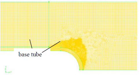
The governing equations with appropriate boundary conditions are solved numerically by the commercial finite volume CFD code ‘Fluent’. The symmetrical section and local mesh of the single row tube is shown in Figure.2. The computational domain is divided into three parts: inlet, middle and outlet. To minimize the effect of the far-field boundary effect, two assistant computational domain zones, inlet and outlet, are setup to reduce the flow distortion. The physical model were extended by 80 and 240 mm respectively to avoid the boundary effects to the results. The computational meshes are generated with commercial software Gambit, using a multi-block hybrid approach. For the central domain with the fins and tube, the tetrahedral unstructured grid is used and the hexahedral structured grid is chosen for the other zone. A grid independent study was examined to ensure the accuracy and the reliability of the numerical methods and to improve the accuracy of the simulation results [18]. Several cases are tested with an increasing grid refinement method to ensure that the solutions are independent of the mesh size. The final grid numbers used are 1, 963, 854, 2, 114, 964, 2, 135, 673 and 2, 165, 112.
(a) Schematic of the computational model
(b) Local mesh
Figure 2. Geometrical computational model and local mesh
At the inlet computational domain, the velocity inlet boundary conditions are specified, which are commonly used to define the flow velocity along with all relevant scalar properties of the flow. In this paper, five velocities and a fixed air temperature of 15 ℃ is appointed at the inlet domain. The outflow boundary conditions are appointed at the exit of the computational domain due to the unchanging flow velocity profile. Two independent fins are chosen to represent the complete wavy fins on the tube, so the periodic boundary conditions are imposed to the interface of the fins. For the middle vertical section of the tube and the central interface of the neighboring tubes, the symmetric boundary conditions are appointed. These approximations are reliable enough for the purpose of this numerical simulation. The temperature of tube wall maintained a constant temperature equal to the saturated temperature of the exhausted steam.
2.4 Numerical result validation
Numerical results in this paper are validated with the experimental data. Experimental tests [19] were carried out on the single-row flattened finned tube using Xi’an Thermal Power Research Institute Co. Ltd. The simulated finned tube and experimental finned tube have the same fin height of 19 mm and fin pitch of 2.3 mm. The variations of the heat transfer coefficient at the air velocity of 1.8 m/s, 2.2 m/s and 2.6 m/s are 5.22 %, 2.64 % and 3.09 % respectively. The variations of the pressure drop are 12.4 %, 6.52 % and 1.92 % respectively. The numerical friction factor and heat transfer coefficient agree well with the experimental results, showing that the computational model and methods are reliable for the purposes of this investigation.
3.1 Non-dimensional parameters
Friction factor and Nusselt number Nu are applied to characterize the flow and heat transfer performance of the finned tube:
$f=\frac{2 \cdot \Delta p}{\rho w_{\min }^{2}}$(6)
where:$\Delta p=\overline{p}_{i n}-\overline{p}_{o u t}$is the pressure drop of cooling air flowing through the finned tubes considering the area-weighted average pressure; $\overline{p}_{i n}, \overline{p}_{o u t}$ are the inlet and outlet average air pressure respectively and $\mathcal{W}_{\min }$is the air velocity at the minimum cross sectional flow area.
The heat transfer coefficient, $h$, of the air-side surface is calculated as follows:
$h=\frac{\Phi}{A \cdot \Delta T_{i n}}$(7)
where $\Phi$ is the air-side heat transfer rate from the finned tube to the air, $\Phi=m c_{p}\left(\overline{T}_{o u t}-\overline{T}_{i n}\right)$; $A$ is the total area of the flattened tube and effective wavy fins $A=A_{t}+\eta_{f} A_{f}$, of which, $A_{f}$is all the fin surface that contacts the air, $A_{t}$ is the flattened tube surface without considering the fin surface which contacts with the flattened tube;$\eta_{f}=\frac{\overline{T}_{f}-\overline{T}_{a}}{\overline{T}_{t}-\overline{T}_{a}}$ is the fin efficiency with $\overline{T}_{a}=\frac{1}{2}\left(\overline{T}_{i n}+\overline{T}_{o u t}\right)$ and $\Delta T_{m}$is the logarithmic mean temperature difference as follows:
$\Delta T_{m}=\frac{\left(T_{t}-\overline{T}_{i n}\right)-\left(T_{t}-\overline{T}_{o u t}\right)}{\ln \left[\left(T_{t}-\overline{T}_{i n}\right) /\left(T_{t}-\overline{T}_{o t t}\right)\right]}$(8)
where $T_{t}$ is the wall temperature of the base tube, $\overline{T}_{i n}, \overline{T}_{o u t}$ are the inlet and outlet average air temperatures.
The Reynolds number is defined as:
$\operatorname{Re}=\frac{\rho w_{\min } D_{e}}{\mu}$(9)
The ratio $\mathcal{E}$ of heat transfer coefficient to power consumption is introduced to evaluate the heat transfer performance with the pressure drop penalty.
$\varepsilon=h / N$(10)
$N=\frac{L p}{1000}$(11)
where$N$is the effective power of the motor; $L$ isis the air flow rate of the fan and $p$ is the pressure of the fan.
3.2 Thermo-flow performance comparison
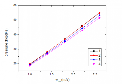
Under TRL conditions and various frontal air velocities, the variations of the pressure drop and heat transfer coefficients of a flattened finned tube and 3 differently dimensioned drop-shaped finned tubes with air velocities are shown in Figure.3 and Figure.4. The Reynolds number varies between 196 and 509 with the frontal air velocity ranging from 1.0 to 2.6 m/s. We can see that the flow resistance and heat transfer coefficient of all of the tubes increases with increasing frontal air velocity. For the same frontal air velocity, Scheme 1 displays the highest flow resistance and heat transfer rate, and Scheme 4 the lowest. Compared to the flattened finned tube, the pressure drop of the drop-shaped Scheme 4 tube reduced by 5.9 % while the heat transfer coefficient reduced by 2.8 % at the frontal air velocity of 1.8 m/s.
Figure 3. Air pressure drop of finned tubes
Figure 4. Heat transfer coefficients of finned tubes
The ratio of heat transfer coefficient and power consumption under various frontal velovities are shown in Figure.5. It can be seen that heat transfer coefficient and power consumption ratio variation of the drop-shaped tube and flattened tube is obvious at low air velocity. The value increases by 2.75-3.75 %. The thermo-flow performance of drop-shaped finned tubes is improved with decreasing of the leeward diameter for the low pressure drop. Scheme 4 shows the best thermo-flow performance, especially at low air velocity.
Figure 5. Heat transfer coefficient versus power consumption under various frontal velocities
3.3 Field synergy principle optimization analysis
According to field synergy principles [20], the performance of convection heat transfer depends not only on the velocity vector and the temperature gradient fields, but also on their synergy. In other words, the better the synergy between the velocity vector and the temperature field, the higher the heat transfer rate of convection. The temperature field and velocity vector field of the middle section of Scheme 1 and Scheme 4 at 2.2 m/s are shown in Figure.6. It can be seen that the intersection angle of the velocity vector and temperature gradient in Scheme 1 is greater than that of in Scheme 4, that is the reason why the convection heat transfer of Scheme 1 is better than that of Scheme 4.
Figure 6. Temperature contour and velocity vector of Scheme1 and Scheme 4
The heat transfer and pressure drop characteristics on the air side of drop-shaped finned tube heat exchangers have been conducted numerically. The thermo-flow characteristics of finned tubes were studied numerically with experimental verifications. The following conclusions can be obtained from this study.
(1) The numerical results agree well with experimental results, showing that the computational model and methods are reliable for the purpose of this investigation. The variations of the heat transfer coefficient at the air velocities of 1.8 m/s, 2.2 m/s and 2.6 m/s are 5.22 %, 2.64 % and 3.09 % respectively. The variations of the pressure drop are 12.4 %, 6.52 % and 1.92 % respectively.
(2) Compared to the flattened finned tube, the pressure drop of the drop-shaped Scheme 4 tube reduced by 5.9 % while the heat transfer coefficient reduced by 2.8 % at the frontal velocity of 1.8 m/s. Scheme 4 produced the best thermo-flow performance especially at low air velocities, benefiting from a lower pressure drop and a moderate heat transfer coefficient.
(3)The intersection angle of the velocity vector and temperature gradient in Scheme 1 is greater than that of Scheme 4, which can explain the mechanism that the thermo performance of Scheme 1 is better than that of Scheme 4. The results obtained can benefit the improvement of air-side heat transfer performance of DACC. The simulation results also need further experimental testing to be verified.
The funding support of this research from the National Basic Research Program of China (No. 2015CB251503) and the North Institute of Water Conservancy and Hydroelectric Power Youth Supporting Program (No. HSQJ2009024) are gratefully acknowledged.
[1] Tawney R., Khan Z. and Zachary J., “Economic and performance evaluation of heat sink options in combined cycle applications”, J. Eng. Gas Turbines Power, vol. 127, no. 2, pp. 397-403, Apr. 2005. DOI: 10.1115/1.1839924
[2] Paul Paikert, “Air-cooled tube condenser,” U.S. Patent 4715432, 1986.
[3] Ranga Nadig, “Fin tube assembly for air cooled heat exchanger and method of manufacturing the same,” U.S. Patent 2009/0173485 A1, 2009.
[4] H. Peter Fay, “Fin tube assembly for air-cooled condensing system and method of making same,” U.S. Patent 7243712, 2007.
[5] Horia A. Dinulescu, “Heat exchanger with finned partition walls,” U.S. Patent 5490559, 1996.
[6] M. S. Mon and U. Gross, “Numerical study of fin-spacing effects in annular-finned tube heat exchangers,” Int. J. Heat Mass Transf, vol. 47, no. 8-9, pp. 1953-1964, Apr. 2004. DOI: 0.1016/j.ijheatmasstransfer.2003.09.034
[7] T. A. Ibrahim and A. Gomaa, “Thermal performance criteria of elliptic tube bundle in crossflow,” Int. J. Therm. Sci., vol. 48, no. 11, pp. 2148-2158, Nov. 2009. DOI:10.1016/j.ijthermalsci.2009.03.011
[8] R. S. Matos, T. A. Laursen, J. V. C. Vargas and A. Bejan, “Three-dimensional optimization of staggered finned circular and elliptic tubes in forced convection,” Int. J.Therm. Sci., vol. 43, no. 5, pp. 477-487, May.2004. DOI: 10.1016/j.ijthermalsci.2003.10.003
[9] Pioro, I. L., Cheng, S. C. “Effect of non-circular cross section geometry and shape on critical heat flux,” Heat Technol, vol. 15, no. 2, pp. 77-87, 1997.
[10] W. M. Yan and P. J. Sheen, “Heat transfer and friction characteristics of fin-and-tube heat exchangers,” Int. J. Heat Mass Transf., vol. 43, no. 9, pp. 1651-1659, 2000. DOI: 10.1016/S0017-9310(99)00229-X
[11] Nemati, H. and Samivand, S. “Simple correlation to evaluate efficiency of annular elliptical fin circumscribing circular tube,” Int. J. Heat Technol, vol. 32, no. 1-2, pp. 233-236, 2014.
[12] Nouri-Borujerdi A., Lavasani A. M., “Experimental study of forced convection heat transfer from a cam-shaped tube in cross flow,” Int. J. Heat Mass Transf.,” vol. 50, pp. 2605-2611, July 2007. DOI: 10.1016/j.ijheatmasstransfer.2006.11.028
[13] Horvat A., Leskovar M. and Mavko B, “Comparison of heat transfer conditions in tube bundle cross-flow for different tube shapes,” Int. J. Heat Mass Transf., vol. 49, no. 5-6, pp. 1027-1-38, March 2006. DOI: 10.1016/j.ijheatmasstransfer.2005.09.030
[14] Cheng Shangmo, Zhao Yongxiang and Chen Gang, “Experimental study of heat transfer and flow resistance of air cross a droplet-shaped tube,” Journal of Engineering Thermophysics, vol. 9, no. 4, pp. 359-361, 1988.
[15] Li Yushi, Zhang Peizhi and Ma Yiwei, “Experiments of the heat-transfer character of the rectangle fin dropwise pipe and the circle fin circle pipe,” Journal of Anshan Institute of Iron and Steel Technology, vol. 11, no. 4, pp. 36-42, 1988.
[16] Liang Xiaoqiang, “Numerical simulation research of rectangular fin tube drop about flow and heat transfer performance,” M.S thesis, Donghua Univ, Shanghai, 2011.
[17] Li Qingling and Zhang Xuanli, “Local heat transfer coefficients of drop-shaped tube,” Journal of Qingdao Institute of Chemical Technology, vol. 11, no. 4, pp. 40-45, 1990.
[18] P. J. Roache, “Perspective: a method for uniform reporting of grid refinement studies,” Trans. ASME, J. Fluids Eng., vol. 116, no. 3, pp. 405-413, Sept.1994. DOI: 10.1115/1.2910291
[19] Chen Shengli, Xue Haijun and Chen Yuling, “Performance of DACC single-row heat exchanger,” Xi’an Thermal Power Research Institute Co. Ltd, 2009.
[20] Guo Zengyuan and Huang Suyi, “Field synergy theory and new techniques for heat transfer enhancement,” Beijing, China, 2004.