OPEN ACCESS
Gas-lift is one of the most widely used artificial lift methods in oil fields to increase oil recovery. Gas-lift unloading processes are susceptible to hydrodynamic instability, as a small change of parameters may result in instability of the gas-lift well unloading. It is therefore necessary to study the parameter sensitivity of the gas-lift unloading process. Considering the characteristics of the unloading transient process, this paper firstly introduces gas-lift instability. A transient dynamic model of the gas-lift well unloading is then built, with four gas lift valves. This is done using a commercially available OLGA dynamic multiphase flow simulator to simulate the transient dynamic gas-lift unloading process. Finally, this paper analyzes the paramter sensitivity of gas-lift unloading, based on OLGA, and determines how the stability of unloading will be affected when given parameters change within a certain range.
Based on the simulation results and analysis, this paper shows that the results provided can be used in gas-lift design, operation and optimization.
Gas-lift, Unloading, OLGA, Simulation, Parameter sensitivity analysis.
Gas-lift is one of the most widely used artificial lift techniques in oil fields. Gas-lift operations inject high-pressure gas from the casing into the wellbore to decrease the density of the gas-liquid mixture and lift the tubing liquid to the surface. The wellbore of a gas-lift well is firstly filled with kill liquid. Before the gas-lift is first operated, the kill liquid above the injection points must be discharged. This process is called unloading. The gas-lift unloading process is a typical transient flow process. In fact, all gas-lift wells are put into production through a transient unloading process. The unloading process is a fluid flow process. Numerical simulation is an important method used to research such fluid flow processes [1, 2, 3]. Many researchers have particularly studied the dynamic analysis methods of gas-lift unloading processes. In 1995, H. Asheim [4] gave an analytical solution of the general gas-lift well unloading model. This used the characteristics of an analytical solution to test the performance of the existing commercial simulator, and indicated that the simulation effect was not consistent with the practical situation in some transient situations. Asheim’s model was aimed at the situation of an oilfield, which is more consistent with practical situations. Existing studies for instability of casing heading have mainly focused on its characterization and on researching the stability criteria [5-9]. Hu B. [10] studied the instability of the gas-lift system. The literature also refers to the simulation of the gas-lift unloading process. Poblano E. [11] and Guerrero-Sarabia I. [12] studied the stability of the gas-lift system and the simulation of the gas-lift unloading process.
Existing studies have mostly tested the design parameters through simulating the actual production process, from the perspective of gas-lift parameter design. Most literature studies the instability of the gas-lift well system from macro perspectives. The production parameters, such as the production index, have some fluctuation but are relatively stable. This paper analyzes the sensitivity of the production parameters of the gas-lift unloading process, based on OLGA. That is; whether the stability of unloading will change when some parameters (production index and injection gas mass flow rate) change, within a certain range, from micro perspectives.
OLGA is a world leading software tool that simulates transient multiphase flow. It can simulate the oil-gas-water state of motion in the oil well, pipeline and oil-gas-water processing plant. This OLGA model had been tested against experimental data over a great range of pressures, geometry scales and varieties of fluid [13]. Using the dynamical simulator to investigate the problem is the most cost-effective method, compared with well experiments and lab experiments. With the development of the dynamic multiphase flow simulator, it becomes more and more practical. The results calculated are relatively accepted by the world’s petroleum companies.
In this paper, the gas-lift instability is initially introduced. A transient dynamic model of gas-lift well unloading is then built, with four gas lift valves. This uses a commercially available OLGA dynamic multiphase flow simulator to simulate the transient dynamic gas-lift unloading process. Finally, the paramter sensitivity of gas-lift unloading is analyzed, based on OLGA, making it possible to determine how the stability of unloading will change when some parameters are altered within a certain range.
Unstable gas-lift will lead to production loss, as well as fluctuating and chaotic, unstable production behavior. Researchers have observed that continuous gas-lift wells can be seriously unstable and sometimes even behave as intermittent gas-lifts. In order to guarantee smooth and optimized production, gas-lift instability problems need to be solved. Hence, it is necessary to understand the mechanisms and characteristics of gas-lift instabilities.
Gas-lift instability research originated from an interest in casing heading, which is a phenomenon caused by a dynamic interaction between injection gas in the casing and the multiphase fluid in the tubing. In fact, most of the literature discussing gas-lift instabilities is directed at solving casing heading problems.
Gas-lift casing heading is described by Xu and Golan (1989) as follows:
(1) Starting at the gas injection point, a sudden reduction of tubing flow pressure results in more gas being discharged through the downhole orifice.
(2) More gas discharge will further reduce flowing pressure; prompting more gas to flow through the downhole orifice.
(3) Since the gas supply through the surface choke cannot meet the higher gas rate discharge into the production string in time, the casing pressure, and thus the upstream pressure at the downhole orifice, will eventually reduce. This results in a decrease of gas flow into the tubing.
(4) The tubing flow pressure now starts to increase, because of the gas injection reduction. This accelerates the reduction of gas injection into the tubing.
(5) The trend is now swayed in the opposite direction. Higher tubing flow pressure and lower upstream pressure means that the downhole orifice can discharge less gas than the surface now supplies. The casing pressure therefore begins to build up.
(6) As the casing pressure is built up, gas flow into the tubing starts to increase. More gas injection reduces the tubing flow pressure and thus sways the flow condition back to step 3.
As the casing pressure is built up, gas flow into the tubing starts to increase. More gas injection reduces the tubing flow pressure and thus sways the flow condition back to step 3.
A comprehensive transient dynamic model of a gas-lift well is built by OLGA. The well consists of two flowpaths: the annulus, which is used to transport the lifting gas from the surface down to the four GLVs (LEAK components); and the tubing, which receives the reservoir inflow and the gas from the four GLVs. The measured depth of the well is 2999.76 m. The outer diameter of the tubing is 0.0889 m. The outer diameter of the annulus is 0.1778 m. The reservoir is modeled with a linear IPR and a reservoir pressure of 300 bara and 95 degrees Celsius. The initial conditions are set so that the well annulus and tubing are filled with water. The injection gas mass flow rate is 0.28 kg/s. The production index for the linear inflow equation is 1.15 Sm3/d/bar. The fluid compositions are taken from the PVTSim database.
Four gas-lift valves (LEAK components) are placed after each other down the annulus. The basic information of each GLV is shown in Table 1. The intention is that the gas-lift valve closest to the wellhead opens first, and as the tubing pressure decreases, this gas-lift valve will close and the next gas-lift valve will open (although this might already be open, depending on the response curve). This cycle is repeated until the injected gas reaches the operating gas-lift valve (lowermost LEAK). Once the gas-lift gas reaches the operating gas-lift valve, gas is continuously injected through this gas-lift valve and stable production is optimized by regulating for the optimum amount of gas. If the tubing pressure is increased for any reason, this may cause the opening of some LEAKs. This opening is the automatic response of the GLVs to stabilize the flow. The injection of gas will reduce the liquid head pressure in the tubing until the LEAKs are closed again.
Table 1. The basic information of the GLV
|
Valve |
1 |
2 |
3 |
4 |
|
The surface closing pressure (psig) |
1786 |
1756 |
1726 |
1598 |
|
The surface opening pressure (psig) |
1813 |
1773 |
1736 |
1605 |
|
The surface debugging pressure (psig) |
1846 |
1668 |
1648 |
1604 |
|
The diameter of the valve (in) |
3/16 |
3/16 |
3/16 |
1/4 |
|
Type |
R20 |
R20 |
R20 |
R20 |
|
The depth of the valve (ft) |
3112.5 |
5537.1 |
7173.8 |
8171.7 |
The trend plots from the simulation results of the unloading process are shown in this section.
4.1 The wellhead casing pressure
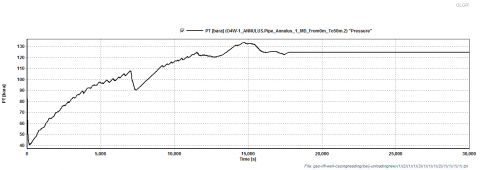
Wellhead casing pressure change against time is shown in Figure 1. The wellhead casing pressure initially increases, and then decreases. This regulation is repeated several times, until the wellhead casing pressure reaches a steady state.
Figure 1. Wellhead casing pressure over time
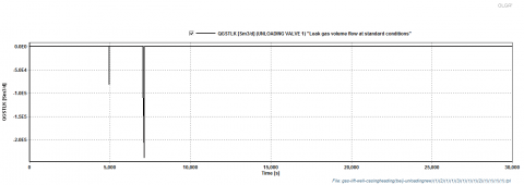
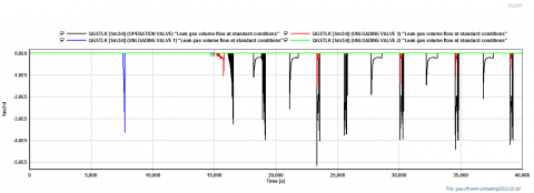
The gas flow rate through gas-lift valves 1, 2, 3 and 4 is shown in Figures 2-5. From the figures, it is possible to note that the four valves open successively. This is what the designer desired and is also consistent with the original, conventional design. It is also clear that, in the unloading process, there occurs the phenomenon that four valves close after they have been open for several seconds. This is due to the GLV response curves and the global system behavior. This cycle is repeated until only the operating gas lift valve opens and works all the time. After 28705 seconds, the gas flow rate through the operating valve maintains a constant value. This means that production has reached a steady-state.
Figure 2. The gas flow rate through gas-lift valve 1
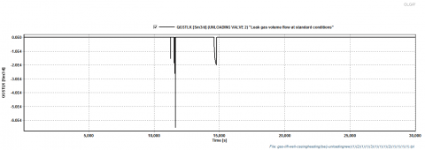
Figure 3. The gas flow rate through gas-lift valve 2
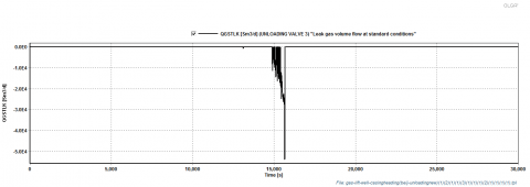
Figure 4. The gas flow rate through gas-lift valve 3
Figure 5. The gas flow rate through gas-lift valve 4
This analysis of the simulation results shows that the original design is reasonable, from a conventional approach. It is simulated that the gas-lift unloading process by OLGA is feasible.
In this section, the paramter sensitivity of gas-lift unloading is analyzed, based on OLGA. How the stability of unloading will change when some parameters are altered within a certain range is then determined.
The change of gas injection rate, production index, dorm pressure and pressure drop between valves are all considered in this section.
5.1 Sensitivity to the gas injection rate
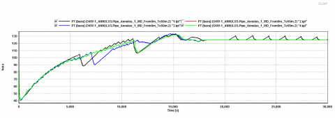
Four different gas injection rates are taken: 0.22 kg/s, 0.24 kg/s, 0.26 kg/s and 0.28 kg/s. Four different models are then built, under four different gas injection rates. The other initial conditions and boundary conditions are the same as for the original model. The four models are simulated simultaneously. The results are shown in Figures 6-10.
Figure 6. The change of wellhead casing pressure over time, under different gas injection rates
Figure 6 shows the change of wellhead casing pressure over time, under four different injection rates. It can be seen from Figure 6 that the unloading rate is much faster after the gas injection rate is increased. The reason for this is that the fluid in the annulus flows more smoothly to decrease the delayed effect. Hence, the wellhead casing pressure is sensitive to the change of gas injection rate.
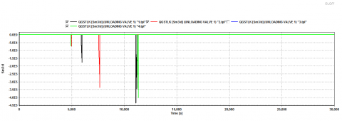
Figure 7. The gas flow rate through gas-lift valve 1 under four different gas injection rates
Figure 8. The gas flow rate through gas-lift valve 2 under four different gas injection rates
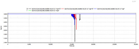
Figure 9. The gas flow rate through gas-lift valve 3 under four different gas injection rates
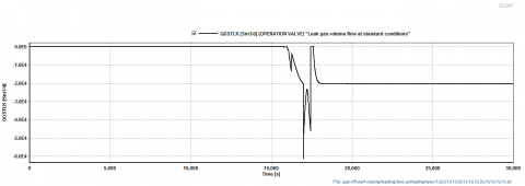
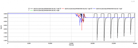
Figure 10. The gas flow rate through the operation valve under four different gas injection rates
It can be seen from Figures 7-10 that the gas injection time for each successive gas-lift valve is earlier. The gas flow rate through the operation valve is also increasing when the production reaches stability in the increase of the gas injection rate.
5.2 Sensitivity to the production index
Changing the production index can also affect the stability of gas-lift well unloading. Four production indices are taken: 0.85 Sm3/d/bar, 1 Sm3/d/bar, 1.15 Sm3/d/bar and 1.30 Sm3/d/bar. This allows the generation of four models, by using four different gas injection rates, but keeping the same other initial conditions and boundary conditions. The four models are simulated simultaneously. The results are shown in Figures 11-15.
Figure 11. The change of wellhead casing pressure over time, under different production indexes
Figure 11 shows the effect of production index on the wellhead casing pressure. It can be seen that it is difficult for the wellhead casing pressure to reach stability when the production index is lower. This indicates that larger production can stabilize the gas-lift well and that the wellhead casing pressure is sensitive to the production index.
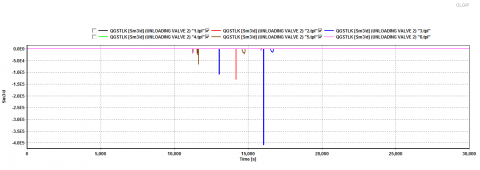
Figure 12. The gas flow rate through gas-lift valve 1 under different production indexes
Figure 13. The gas flow rate through gas-lift valve 2 under different production indexes
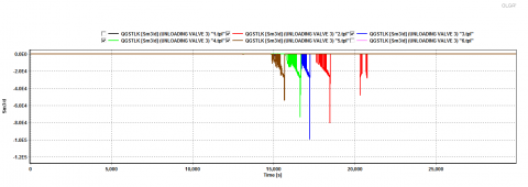
Figure 14. The gas flow rate through gas-lift valve 3 under different production indexes
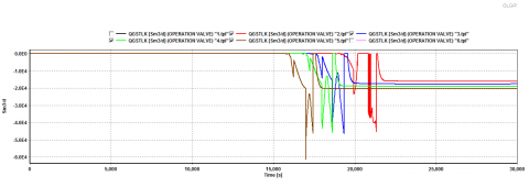
Figure 15. The gas flow rate through the operation valve under different production indexes
Figures 12-15 show the changing process of the gas flow rate through each gas-lift valve with a changing of the production index. When the fluid production ability of formation is poor and the result is shown in a black curve, the work of the operation valve has an unstable status. The reason for this is mainly that the effect of injection gas on the fluctuation of tubing pressure is large, given just a small change in the production index. The gas injection pressure can be decreased to keep the operation valve stable. Hence, the gas flow rate through the gas-lift valve is sensitive to the production index.
5.3 Sensitivity to the dorm pressure
The dorm pressure determines the opening and closing pressure of a gas-lift valve. If the dorm pressure is not reasonable, it will influence the normal unloading of the gas-lift well. The dorm pressure of the uppermost gas lift valve is increased by 0.5 MPa. The simulation is then performed. The results are showed in Figures 16 and 17.
Figure 16. The gas flow rate through each gas-lift valve over time as the dorm pressure of the uppermost gas-lift valve is increased
Figure 17. The wellhead casing pressure over time as the dorm pressure of the uppermost gas-lift valve is increased
It can be seen from the simulation results that increasing the dorm pressure of the first valve will increase the opening pressure of the first valve. In the unloading process, the first valve closes earlier and no gas is injected through it. The injected gas initially enters the tubing through the second valve, which means that the liquid volume in the tubing is so large before gas enters the tubing that the wellhead casing pressure increases. Hence, the gas flow rate through each gas-lift valve and the wellhead casing pressure are both sensitive to the dorm pressure.
5.4 Sensitivity to the pressure drop between valves
The pressure drop between the operation valve and the third valve has great implications for the unloading process. In order to prevent abnormal opening of the operation valve due to pressure fluctuations, the pressure drop between the operation valve and the third valve is greater than that between the upper valves. The dorm pressure of the operation valve is increased by 0.2 MPa and the unloading process is then simulated. The simulation results are shown in Figure 18.
Figure 18. The gas flow rate through gas-lift valves over time, after the dorm pressure of the operation valve is increased
It can be seen from Figure 18 that the operation valve is on and off at times and that production is not stable after the pressure drop between the operation valve and the third valve is decreased. The gas flow rate through each valve is sensitive to the dorm pressure of the operation valve.
The gas-lift unloading process is the basis of the production process. A reasonable unloading process can shorten unloading time, advance unloading efficiency and keep production stable. In this paper, a comprehensive transient dynamic simulation of gas-lift well unloading has been carried out using OLGA. A parameter sensitivity analysis of the unloading process is given. The results provided in this paper can be used in gas-lift design, operation and optimization. The following conclusions can be obtained from this study.
(1) The gas injection rate determines the length of time for gas-lift unloading. The larger the gas injection rate, the shorter the unloading time. However, if the gas injection rate is too large, it results in high casing pressure and the gas-lift valves cannot close normally. Multi-point gas injection therefore occurs. At the same time, too large a gas injection rate will damage the gas-lift valves and enhance the ground gas injection pressure. The gas injection rate must therefore be increased gradually.
(2) For each production index, there is a reasonable gas injection rate.
(3) The pressure drop between valves guarantees that the injection gas enters the tubing through a single valve. Too large a pressure drop between valves will decrease the gas injection depth, but too small a pressure drop will result in multi-point gas injection.
(4) The pressure drop between the operation valve and the third valve must be relatively large. If this pressure drop is too small, it will result in multi-point gas injection or unstable work of the operation valve.
The authors wish to thank the people of the Branch of Key Laboratory of CNPC for Oil and Gas Production for their great help. This paper is supported by Educational Commission of Hubei Province of China (B2015449) and the National Natural Science Foundation of China (61572084). It is also supported by the Key Laboratory of Exploration Technologies for Oil and Gas Resources.
1. F. Corvaro, G. Nardini, M. Paroncini, et al., “PIV and numerical analysis of natural convective heat transfer and fluid flow in a square cavity with two vertical obstacles,” International Journal Of Heat and Technology, vol.33, no.2, pp.51-56, 2015. DOI: 10.18280/ijht.330208.
2. Hong Yin, Dong Sun, Xingyuan Li and Ping Huan, “Airflow simulation of linear grating lithography workshop,” Journal of Heat and Technology, vol.33, no.2, pp.109-114, 2015. DOI: 10.18280/ijht.330218.
3. H. Bounaouara, H. Ettouati, H. Ben Ticha et al., “Numerical simulation of gas-particles two phase flow in pipe of complex geometry: pneumatic conveying of olive cake particles toward a dust burner,” International Journal of Heat and Technology, vol.33, no.1, pp.99-106, 2015. DOI: 10.18280/ijht.330115.
4. H. Asheim, Verification of Transient, Multi-Phase Flow Simulation for Gas Lift Applications, SPE56659, 1999: 1-16. DOI: 10.2118/56659-MS.
5. F.J.S. Alhanati, Zelimir Schmidt, D.R. Doty, et al., Continuous Gas-Lift Instability: Diagnosis, Criteria, and Solutions, SPE 26554, 1993. DOI: 10.2118/26554-MS.
6. Asheim, H., Criteria for Gas Lift Stability, JPT, vol.40, no.11, pp.1452-1456, 1988. DOI: 10.2118/16468-PA.
7. Avest, D.ter and Oudeman, P., A Dynamic Simulator to Analyze and Remedy Gas Lift Problems, SPE 30639, 1995. DOI: 10.2118/30639-MS.
8. Blick, E.F., Enga, P.N., Lin, P.C., “Stability analysis of flowing oil wells and gas-lift wells,” SPE Production Engineering, vol.3, no.4, pp504-514. DOI: 10.2118/15022-PA.
9. Xu, Z.G. and Golan, M., Criteria for Operation Stability of Gas Lift, SPE 19362, 1989. DOI: 10.2118/19362-MS.
10. Hu B. Golan M., Gas-lift Instability Resulted Production Loss and Its Remedy by Feedback Control: Dynamic Simulation Results, SPE 84917, 2003. DOI: 10.2118/84917-MS.
11. Poblano E., Camacho R., Fairuzov, Y.V., “Stability analysis of continous-flow gas lift wells,” SPE Production and Facilities, SPE77732, 2002.DOI: 10.2118/77732-MS.
12. Guerrero-Sarabia I., Fairuzov Y.V., Stability Analysis of Gas Lift Wells Used for Deepwater Oil Production, SPE 104037, 2006. DOI: 10.2118/104037-MS.
13. K. H. Bendlksen, Dag Malnes, Randl Moe, et al., The Dynamic Two-Fluid Model OLGA: Theory and Application, SPE19451, vol.6, no.02, pp171-180, 1991. DOI: 10.2118/19451-PA.