OPEN ACCESS
This article addresses a construction prepared to allow the function of an outboard engine in conditions similar to the factual. An outboard gasoline engine with max power 4HP was placed on the referred construction. In order to measure the performance of the entire powertrain, a prototype measurement procedure was developed. According to this procedure the measurement of the force is made by a direct connection between the engine’s rpm and applied load. During the measurements operating characteristics of the engine, as well as the exhaust gases, were recorded. For the measurement of the emitted pollutants, a laboratory protocol and measurement standards defined by 40 CFR 1045 were used.
(Presented at the AIGE Conference 2015)
Outboard engine, Gas emissions, Output load, Pollutant emissions, Measurement standard.
Environmental protection has a growing progressive course on international concern driving engineers’ continuous attempts at reducing polluting emissions. Lately, notice has been given to transportation, bringing marine craft engines to the foreground. Universal organizations such as CIMAC, CARB and IMO in collaboration with Government Agencies care to establish strict regulations to achieve the desired results. Those actions are not newborn, but only in the recent years they affected the small engines as well as the motors of large vessels. The four stroke outboard petrol engine is one of the most sellers popular for recreational boats, and this puts it on the center of attention. [1]
Outboard engines can cover a wide range of needs from recreational craft and small boats to speedboats. The capability vary among the strength of each machine witch starts from max power two PS and can reach up to three hundred and fifty HP. The engine may be two or four stroke, depending on the burning times. Two stroke engines have a simple construction and are always lighter, since they consist of less parts. In comparison to the four stroke, two stroke engines receive larger amounts of stress, and the fuel comsumption is remarkably larger. These two types of engines come with different pros and cons; however the four strokes have gained popularity due to its technological developments on the last decade. Nowdays, two stroke engines with lower fuel consumption and gas emissions there are available in the market, however this causes a significant cost increase. [2]
The outboard engine was invented in the early twenties by Gustave Trouvé and changed permanently the way of travelling at sea. It is a propulsion system for boats, designed to be placed on the vessels’ transom and consisting of a self contained unit that includes the engine, a gearbox and a propeller. In addition to movement outboard engines provide steering control of the boat, as they are designed to rotate on their mounting material and thus control the direction of thrust. The direction is controlled by the lower unit that functions as a rudder [3].
The engine operates as follows; initially the fuel is combusted in the cylinder (or cylinders) for power generation. The number of cylinders can vary from one to eight. Thereafter the piston, supplied from the combustion and expansion of the exhaust gases, moves back and forth within the cylinder gradually completing the four or two cycle times. This process is similar to that performed on cars and any classic four or two stroke engine.
As a result, the piston rod rotates the crankshaft, converting the rectilinear reciprocating motion to rotary. The crankshaft, consequently, rotates the main drive shaft that extends along the lower ridge of the engine. On the bottom of the hinged there is a small gearbox which converts the vertical pivotal movement in a horizontal rotary movement [2, 3, 4, 5].
The legislation for emissions from marine engines and therefore outboard engines began in 1998. The first tests conducted, focused on the effects on the undersea environment and didn’t conclude to meaningful results. Not only the results didn’t show an increase in pollutants but there were studies implying an improvement in the undersea environment. That makes the reason why the legislations were delayed understandable. Soon scientists realized that the actual need for tests should be concentrated to the air pollutants. USA pioneered implementing the exhaust emission legislation for outboard motors. The US EPA regulations started for 1998 outboard models and aimed at a 75% reduction to 2006 through a progressive scale. Alongside, Europe’s regulations for pollutant emissions did not include motor boats until 2003 [2, 3, 4, 5].
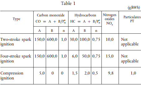
The directive 94/25/EC establishes the essential requirements for exhaust emissions from marine propulsion engines as showed in Table 1. As the directive suggests propulsion engines must be designed, constructed and assembled in a way that when correctly installed and in normal use, their emissions shall not exceed the limit values laid down in Table 1[6].
Table 1. The exhaust emissions of the marine propulsion engine [6]
Where A, B and n are constants in accordance with table, PN is the rated engine power in KW and the exhaust emissions are measured in accordance with the harmonised standard [6].
For engines above 130kW either E3 (IMO) or E5 (recreational marine) duty cycles may be used [6].
The reference fuels to be used for the emissions test for engines fuelled with petrol and diesel shall be as specified in Directive 98/69/EC (Annex IX, Tables 1 and 2) and for those engines fuelled with Liquefied Petroleum Gas as specified in Directive 98/77/EC [6].
The measurement of exhaust emissions in accordance with the harmonized standard EN ISO 8178-1: 1996. It is described in detail the standard according to which the measurement must be fulfilled [7].
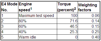
Duty Cycles: Exhaust emission measurements are to be conducted in relevance to the power of the motor in question. ICOMIA 34-88 describes the standard measurement of exhaust gas marine engines and connects directly to ICOMIA 36-88 [Annex IV] standards that determines which loads and speeds should be used. This information is displayed in Table 2[8].
Table 2. The five modes of the duty cycle [8]
The first mode the engine should start operating on is the fifth, this aims to the determination of the maximum torque of the rated speed. The remaining modes shall be performed in the decreasing order of speed and power as shown on table 2.
These duty cycles illustrate a measurement of separately conducted modes. If the measurement is to be consecutive the time each mode lasted must be noted. Cycles described in ISO associate operational modes with transitions of twenty seconds and the entire test sequence must be performed in a specified period of time without interruption.
Duty cycles according to the American standards:
Table 3. Duty cycle for discrete mode testing [9]
Note: 1Speed terms are defined in 40 CFR part 1065. Percent speed values are relative to maximum test speed [9].
2Except as noted in §1045.505, the percent torque is relative to maximum torque at maximum test speed [9].
Table 4. Duty cycle for ramped modal testing [9]
Note: 1Speed terms are defined in 40 CFR part 1065. Percent speed values are relative to maximum test speed [8].
2Advance from one mode to the next within a 20 second transition phase. During the transition phase, command linear progressions of speed and torque from the speed setting of the current mode to the speed setting and torque setting of the next mode [9].
On a four stroke outboard engine, with 4Hp max power output, measurements of speed and load took place. The measuring system used is composed of an rpm meter, a dynamometer (meter of force), a signal converter, the data collection unit NI cDAQ-9174 (DAQmx) with the module measurement NI 9205 and a laptop computer.
The speed was measured with an rpm meter connected on the outboard engine and at the same time on the computer. The results were shown on the computer through the NI LabVIEW software.
The dynamometer was used to measure the load. Proper circuit connections were made between the dynamometer the signal converter and the data collection unit NI cDAQ-9174 (DAQmx), so that the last would be able to process the signal. The DAQmx has a variety of modules for measures, the one chosen was the NI 9205 suitable for measuring analog inputs. The signal, coming from the link mentioned above was led to the portable computer and the use of NI LabVIEW made the depiction and later procession of the results possible.
The outboard engine was placed in a tank filled with tab water. The engine is placed and tied on a prototype device which allows movement towards one axis, and then fastened to the measuring system mentioned above, aiming to simulate real conditions of outboard use during its operation. Measurements performed from the idle position up to the last position of the throttle without exceeding the load of 500N. At the same time we started from 1500 rpm increasing by five hundred until we approached 4000 rpm. When we were reducing the speed we were following the same course vice versa, and measuring simultaneously the values of the load. The measurement at each rpm value (with these to remain as constant as possible) lasted about one minute. Maximum rpm value was decided that of 4000 as after that value no change of the load was observed.
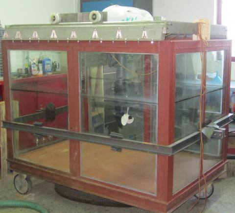
The engine used is four strokes, gasoline outboard and is intended for use in small crafts or as an auxiliary engine on larger vessels. For the affixing of the outboard a special installation has been constructed. This feature was designed to enable motion during the machine’s operation. In other words, to simulate actual operating conditions of the engine as if it was placed on a vessel.
Figure 1. The stainless steel construction mounted on the tank
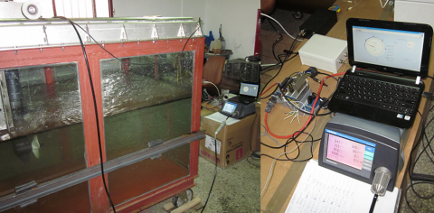
Figure 2. The test measurement unit
Figure 3. The test measurement unit - the engine function
Figure 4. The testing table during the measurement
The force of the outboard was measured through the traction force exerted on a digital scale. The rpm signal reception was achieved by connecting an inductive rpm sensor between the spark plug and the multiplier. Finally the exhaust gas has been collected by the idle hole of the outboard, where a metal threaded connector M8x1 retaining two Φ6 tails, was placed. On the first tail, the exhaust sample pipe was plugged and on the other one a k-type thermocouple was connected.
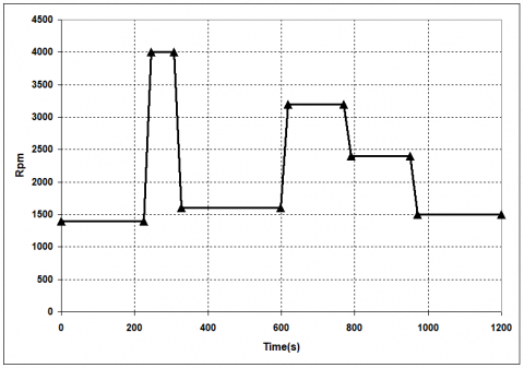
Measurement protocols: Measurements where performed with two different structures. The first one was a pyramid measuring scale with engines revolutions per 500 rpm. Its purpose was to create a connection between thrust and rpm (Fig 5). The second structure followed the standards of measurements set by the American legislation for marine engines (Fig 6):
Figure 5. The pyramid of engine rpm
Figure 6. The engine rpm variation according the American legislation
The rpm pyramid protocol:
Table 5. The rpm/engine speed/duration for pyramid structure generation
|
Rpm |
Engine speed |
Duration (sec) |
|
Idle |
Idle |
240 |
|
1500 |
37,5% |
240 |
|
2000 |
50% |
240 |
|
2500 |
62,5%% |
240 |
|
3000 |
75% |
240 |
|
3500 |
87,5% |
240 |
|
4000 |
100% |
120 |
Figure 7. The pyramid of engine rpm in real conditions
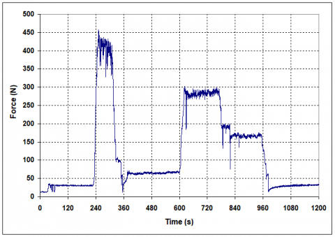
Figure 8. The force variation in relation to the time on the pyramid of engine rpm
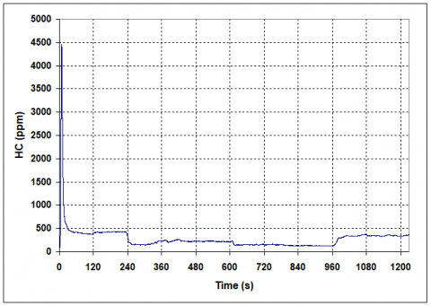
Figure 9. The HC variation on the pyramid protocol
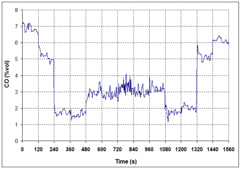
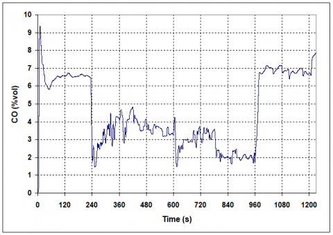
Figure 10. The CO variation on the pyramid protocol
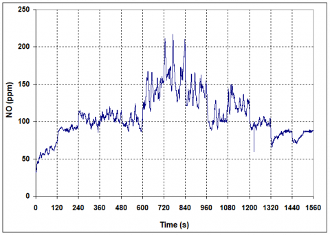
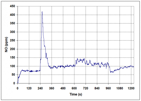
Figure 11. The NO variation on the pyramid protocol
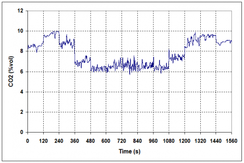
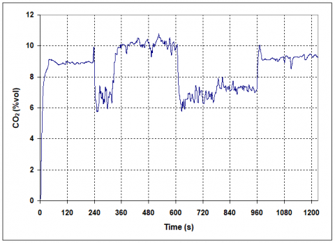
Figure 12. The CO2 variation on the pyramid protocol
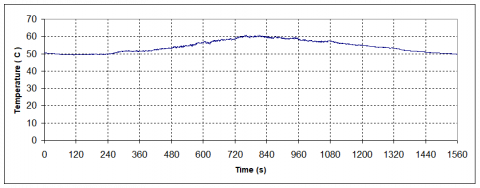
Figure 13. The temperature variation on the pyramid protocol
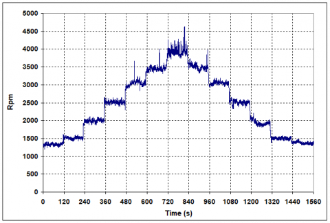
American protocol:
Table 6. The rpm/engine speed/duration for American structure generation
|
Rpm |
Engine speed |
Duration (sec) |
|
Idle |
Idle |
474 |
|
4000 |
Max speed |
83 |
|
1600 |
40% |
291 |
|
3200 |
80% |
171 |
|
2400 |
60% |
181 |
Figure 14. The engine rpm in real conditions on American protocol
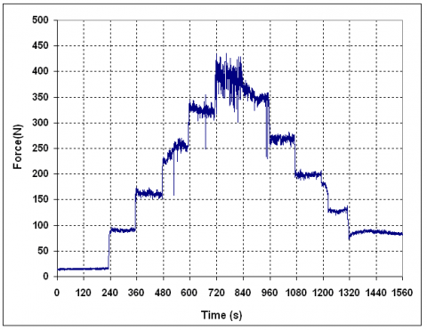
Figure 15. The force variation in relation to the time on American protocol
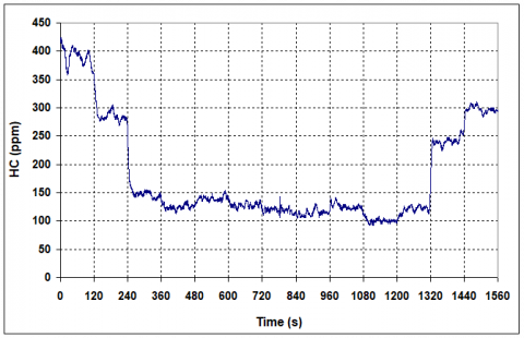
Figure 16. The HC variation on American protocol
Figure 17. The CO variation on American protocol
Figure 18. The NO variation on American protocol
Figure 19. The CO2 variation on American protocol
Figure 20. The temperature variation on American protocol
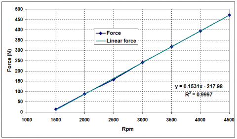
Leaving aside the fact that the maximum speed of the actual measurements was 4000 rpm, the instantaneous value of the load at 4500 rpm was measured to be 472.1945 N. As shown in Fig 21 the loading of the motor increases linearly with the increase of speed. Also, in Fig. 22 the linearity is obvious while force -measured during the measurement of the pyramid protocol - is displayed as a percentage of maximum the force.
Figure 21. The force variation in relation to the engine rpm
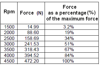
Table 7. Rates of force at various engine speeds
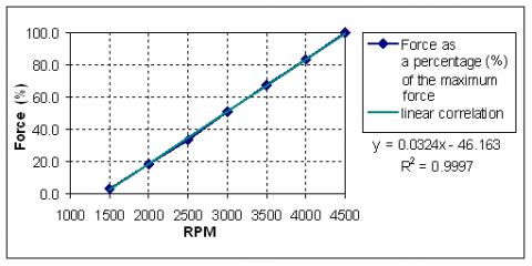
Values from table 7 created the diagram of Fig 22, showing that equation relating the measures sizes is linear.
Figure 22. The force, as a percentage of the maximum power, variation, in relation to the engine rpm
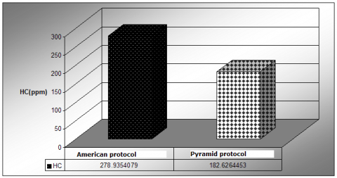
Figure 23. The HC average
Figure 24. The CO average
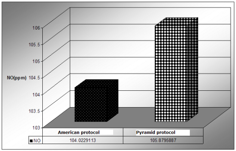
Figure 25. The NO average
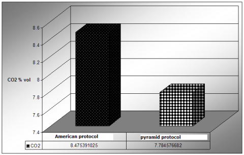
Figure 26. The CO2 average
When comparing the two protocols for their gaseous emissions’ average rates the results came out to be as shown on figure 23 to figure. 26. As displayed on the images HC, CO and CO2 have significantly higher rates on tests using the American protocol. This difference derives from the different time spent on each speed for each standard. The abnormal transitions from low revs to the highest and then back to low ones combined with the large idle times, makes the choice of the American protocol unambiguous for exhausts are being measured during the most adverse operating conditions.
The NO comparison had the exact opposite form. The American protocol displayed less NO emissions than the Pyramid protocol, matching the results of the temperature comparison. The formation of nitrogen oxides, in internal combustion engines, is related to the temperature. As higher the temperature as higher the formation of nitrogen oxides is.
Measuring the outboard’s load with the digital scale proved to be sufficient to determine the applied load to the engine. The digital scale that gives the pyramid protocol, with the engine speed to increasing from the idle until to the maximum engine speed with steps of 500rpm and then decreasing with the same step until the idle speed, gives a clear view of the engine power by the measurement of the thrust force of the outboard engine. The results are trustworthy, and the measurement represents the actual power of the engine, in addition no further calculations need to be done as the thrust force is the final result of the engine power, the transmition rate and propeller step. Compared to other procedures this is the one recommended, as the measuring conditions are ideal, there is minimum deviation from the factual operating conditions and is more readily applicable. The disadvantage of this test may be identified through the results, which can be faced by solving operating problems. As the tank was not big enough, the engine created a wave, which led to great fluctuations when the speed reached or surpassed 4000rpm, for the power of the specific outboard engine. This problem is of minor significance and can be solved by using a larger tank or by creating a furrow opposite to the propeller, which will be inducing a circular flow of the tank water. In addition, the wheels’ friction caused a thrust variation of 29.43N, mean value, when moving from high to low rpm, compared to the respective values during the increase of the engine speed. This can be surpassed by affecting to the load measurement when this transition occurs, so to have movement of the motor base and the causing of measurement in the direction of outboard thrust, this will be aiming to measure the thrust without price variation for the same rpm value. Finally the exhaust temperature seems to have low value; this is associated with the measurement point. The temperature sensor is placed in the idling hole for the exhaust gases, so to not make any change in the body of the outboard engine. If the measurement took place on the main exhaust pipe then the prices should be higher but in this case the sensor cable and possibly the sensor would be in the water.
Unfortunately, Prof. Arapatsakos Charalambos passed away on 07.24.2015. But at first, he wrote a letter for thanking Prof. Enrico Lorenzini.
1. http://mechanicadvisor.com/articles/inboards-vs-outboards, Retrieved 19-3-2015.
2. Stocktaking study on the current status and developments of technology and regulations related to the environmental performance of recreational marine engines: final report, January 10, 2004, Contributors: Rijkeboer, R.C.
3. http://en.wikipedia.org/wiki/Gustave_Trouv%C3% A9#Inventions, Retrieved 31-5-2014
4. http://www.maritimejournal.com/news101/power-and-propulsion/two-stroke-outboards-still-available-at-seawork, Retrieved 31-5-2014
5. Woodford, Chris, “Outboard Motors”, Retrieved 31-5-2014. 6. Directive 94/25/EC, http://eurlex.europa.eu/LexUriServ/LexUriServ.do?uri=CONSLEG:1994L0025:20031120:en:PDF, Retrieved 31-5-2014.
7. ISO 8178-1:2006, http://www.iso.org/iso/home/store/catalogue_ics/catalogue_detail_ics.htm?csnumber=42714, Retrieved 31-5-2014.
8. ICONOMIA Standard 34-38, ICONOMIA Standard 36-88, http://www.icomia.com/library/Default.aspx?LibraryDocumentId=945, Retrieved 31-5-2014.
9. 40 CFR Part 1045, Appendix II to Part 1045 - Duty Cycles for Propulsion Marine Engines, http://www.law.cornell.edu/cfr/text/40/part-1045/appendix-II, Retrieved 31-5-2014.